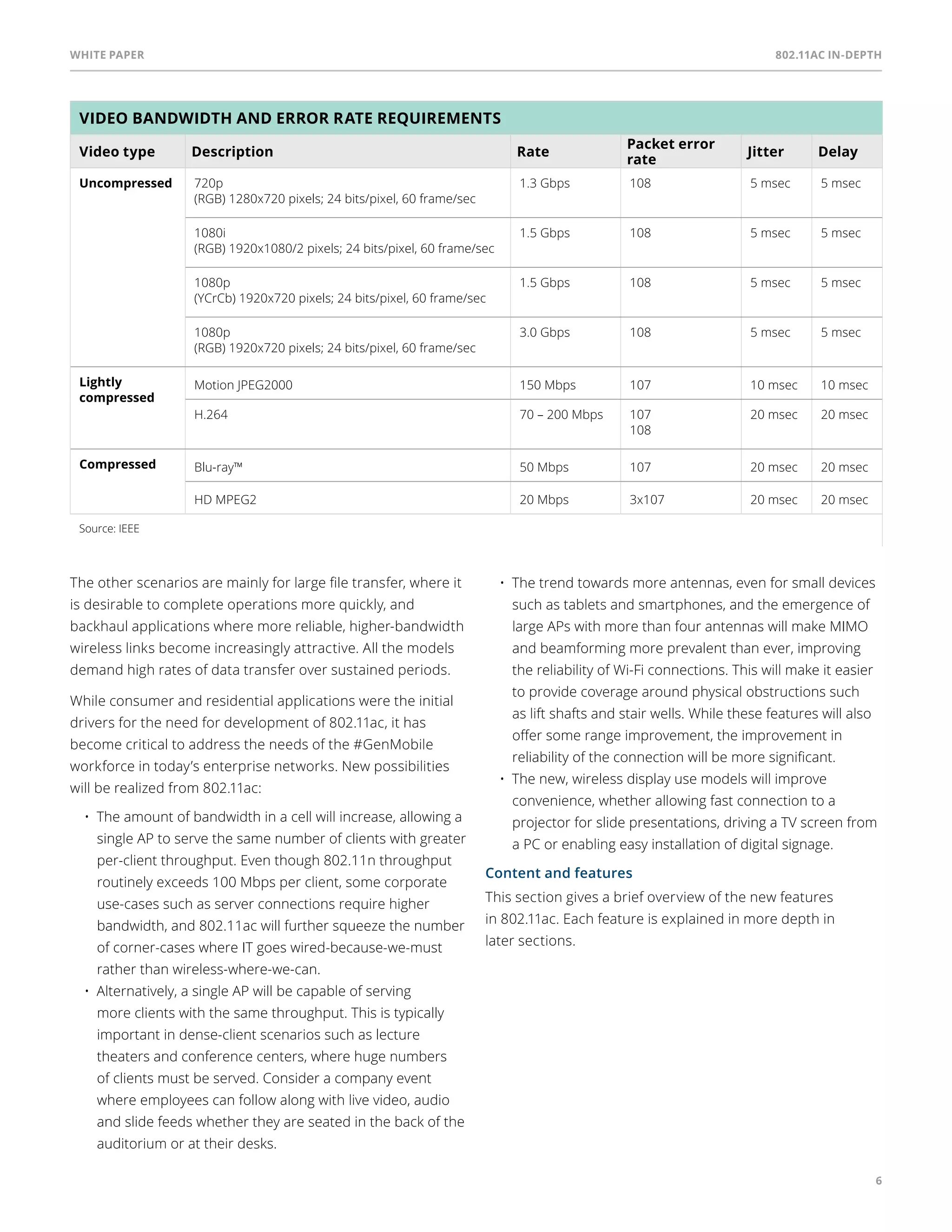
White paper 
802.11ac In-Depth
Table of Contents 
3 
4 
9 
19 
35 
36 
introduction 
802.11ac technology fundamentals 
PHY Layer Enhancements 
MAC Layer Enhancements 
About Aruba Networks, Inc. 
references
White paper 802.11ac In-Depth 
3 
Introduction 
Wi-Fi has become such an amazingly successful technology 
because it has continuously advanced while remaining 
backwards compatible. Every few years since the 802.11b 
amendment was ratified, the industry has released successive 
amendments increasing Wi-Fi data rates and capabilities, but 
even the latest Wi-Fi systems are able to interoperate with 
1999 equipment built to the original standard. This paper 
explains the latest advance in Wi-Fi, 802.11ac, which provides 
the next step forward in performance. 
The current state-of-the-art Wi-Fi is known as Wi-Fi 
CERTIFIED n or 802.11n. In the four years since the Wi-Fi 
Alliance introduced its initial certification, this technology has 
become hugely popular. According to IHS iSuppli, 802.11n 
now accounts for over two-thirds of Wi-Fi chipset shipments, 
and is on track to take over completely from 802.11a/b/g in 
mainstream applications before the end of 2012. 
802.11n has become popular because it improves 
performance. The five-fold increase in bandwidth, along 
with improved reliability from multi-antenna MIMO 
techniques, has delivered a better user experience. In fact, 
a 2007 Burton Group report entitled “The end of Ethernet” 
accurately predicted a future where Wi-Fi will take over 
from wired Ethernet as the primary edge connection for 
corporate networks. 
Figure 1 
Figure 2 
802.11b chipset shipments (k) 
802.11g chipset shipments (k) 
802.11a chipset shipments (k) 
802.11 combo chipset shipments (k) 
802.11n chipset shipments (k) 
GLOBAL SHIPMENT FORECAST FOR WIRELESS 
LOCAL AREA NETWORKING WLAN CHIPSETS 
2009 2010 2011 2012 2013 2014 
(millions of units) 
Wi-Fi chipset shipments and penetration of 802.11n (actual & forecast) 
2,500 
2,000 
1,500 
1,000 
500 
0 
Source: iSuppli 
WLAN CHIPSET FORECAST BY 
TECHNOLOGY STANDARD 
100% 
75% 
50% 
25% 
2007 2008 2009 2010 2011 2012 2013 
0% 
X X 
X 
X 
Wi-Fi chipset forecast for 802.11ac chipsets (millions) 
2,500 
2,000 
1,500 
1,000 
500 
0 
X 
Source: ABI research 
2012 
2010 
X 
2015 2016 
2014 
802.11n/802.11ac 
802.11n (2.4 GHz) 
802.11n (dual-band) 
X 802.11ac (5 GHz) 
X 
2013 
2011
White paper 802.11ac In-Depth 
4 
As 802.11n has become a standard interface on PCs, tablets 
and smartphones, the applications used by these devices 
have continued to progress. Mobile technology has 
encountered the next frontier – video. Whether delivering 
YouTube to smartphones or moving HDTV signals around the 
office or home, video has become a significant driver of 
network traffic, chiefly because it requires one or two orders 
of magnitude more bandwidth than other IP services. Now 
the 100 Mbps or 200 Mbps rates enabled by 802.11n, 
breakthrough figures that put it on a par with 10/100 Mbps 
Ethernet just a few years ago seem barely adequate for some 
emerging video applications. 
Luckily the IEEE 802.11 working group and the Wi-Fi Alliance, 
the industry bodies standardizing Wi-Fi are already working 
on 802.11ac, the successor standard to 802.11n and its 
corresponding interoperability certification program. The 
IEEE 802.11ac amendment is expected to achieve final IEEE 
ratification at the end of 2013. Concurrent work in the WFA 
will result in a certification program which is expected to 
launch early in 2013, based on a draft of the IEEE 802.11ac 
document, as was done with 802.11n. 
802.11ac is a set of physical layer enhancements for higher 
throughput in the 5-GHz band, chiefly with video in mind, and 
to achieve this it extends the techniques pioneered in 
802.11n: More antennas, wider channels and more spatial 
streams, along with a number of new features to boost 
throughput and reliability. 
802.11ac can be considered the next step after 802.11n, along 
the path running from 11b, to 11a/g, then 11n, and now 802.11ac. 
And it is likely to be introduced along with related amendments 
to 802.11 including video-related improvements in 802.11aa 
(video transport streams) and 802.11ad (very high throughput, 
short-range at 60 GHz). New products that incorporate 802.11ac 
will become available near the end of 2012. 
In the same way that chip vendors have now switched 
production almost completely to 802.11n, even for low-cost, 
low-power applications such as smartphones, 802.11ac will 
become the de-facto standard for 5-GHz equipment in a few 
years. The chart on page 3 from ABI shows one set of forecasts. 
This white paper explains the techniques behind 802.11ac. It 
is intended for those who share our enthusiasm for wireless, 
to use these insights to become better engineers and users 
of Wi-Fi technology. 
802.11ac technology fundamentals 
The current generation of 802.11ac Wave 1 products, that 
have been certified by the Wi-Fi Alliance since mid 2013, 
deliver a three-fold increase in performance. This is driven by 
a doubling of channel bandwidth to 80 MHz, addition of a 
more efficient 256-QAM encoding technique and explicit 
transmit beamforming to improve signal quality. 
The 802.11ac project title succinctly reads “Enhancements for 
Very High Throughput for operation in bands below 6 GHz.”1 
There are more details in the scope paragraph: 
This amendment defines standardized modifications to both 
the 802.11 physical layers (PHY) and the 802.11 Medium 
Access Control Layer (MAC) that enable modes of operation 
capable of supporting: 
• A maximum multi-station (STA) throughput (measured at 
the MAC data service access point), of at least 1 Gbps and 
a maximum single link throughput (measured at the MAC 
data service access point), of at least 500 Mbps. 
• Below 6-GHz carrier frequency operation excluding 
2.4-GHz operation while ensuring backward compatibility 
and coexistence with legacy IEE 802.11 devices in the 
5-GHz unlicensed band. 
It’s clear that the goal is to continue the thrust of 802.11n to 
extend rates and throughput. To simplify the task, 802.11ac is 
restricted to below 6 GHz, and in practice, to 5-6 GHz, as it 
applies only to the 5-GHz bands. 
The important new technologies in 802.11ac should be 
considered as extensions of the physical layer wireless 
techniques pioneered in 802.11n, notably using multiple 
antennas at the transmitter and receiver to exploit multiple 
input/multiple output (MIMO) for parallel delivery of multiple 
spatial streams. 
Most of the features extend the limits of 802.11n, adding 
more antennas, more spatial streams, wider RF channels and 
higher-level coding. New mechanisms are also defined, 
notably multi-user MIMO where an access point (AP) 
transmits simultaneously to multiple clients. 
1 Note: The IEE 802.11 standard refers to the PHY rates of 802.11n as high throughput (HT) and those of 802.11ac as very high throughput (VHT) while those prior 
to 802.11n are non-HT. We will avoid using these terms in this paper: there are plenty of acronyms here already, but readers who wish to read the IEE documents 
(available at http://standards.ieee.org/about/get/) should be aware of HT and VHT.
White paper 802.11ac In-Depth 
5 
802.11ac usage models 
Category Usage Model Category Usage Model 
1. Wireless Display 1a. Desktop storage & display 3. Rapid Upload/Download 3a. Rapid sync-n-go file transfer 
In its preparation for developing the actual standard, the IEEE 
identified a set of use models or scenarios in which 802.11ac 
will enable us to use Wi-Fi to support new functionality, or 
improve the performance of existing tasks. 
This wide-ranging list shows the recurring theme of current 
Wi-Fi developments and the pervasive influence of video. 
Streaming video, even when compressed, consumes orders 
of magnitude more bandwidth than email, web browsing, or 
voice communication. 
It has already transformed the cellular industry, where the 
introduction of smartphones and now tablets has triggered 
enormous increases in bandwidth demand, while 
consumption of streaming video-over-IP in the home for TV 
and movies is driving significant increases in Internet traffic. 
The engineers involved in 802.11 and Wi-Fi are extending 
their standards and protocols in response to this revolution, 
anticipating that higher available rates will continue to drive 
both the amount of video content consumed, and also the 
demand for increased video fidelity, as consumers 
increasingly prefer bandwidth-hungry HDTV over standard 
definition TV. 
The wireless display usage models are particularly 
interesting, as they show Wi-Fi attacking the cross-room 
cable replacement market that for a while was the objective 
of ultra-wide band (UWB) and that will overlap with the 
802.11ad work at 60 GHz. Its intent is to replace the cables 
between set-top boxes, game consoles, PCs and TV monitors 
where the requirement is for very high data rates but 
relatively short distances. While some 802.11n vendors have 
already made initial forays into this market, most consumer 
electronics companies see 802.11ac and 802.11ad as the first 
viable wireless technologies for video, especially 
uncompressed video. 
1b. Projection on TV or projector 
in conference room 
3b. Picture by picture viewing 
1c. In-room gaming 3c. Airplane docking 
1d. Streaming from camcorder 
to display 
3d. Movie content download to car 
1e. Broadcast TV field pick up 3e. Police/surveillance car upload 
2. Distribution 
of HDTV 
2a. Lightly compressed video 
streaming around the home 
4. Backhaul 4a. Multi-media mesh backhaul 
2b. Compressed video streaming 
around the home 
4b. Point-to-point backhaul 
2c. Intra-Large vehicle 
(e.g. airplane) applications 
5. Outdoor campus/auditorium 5a. Video demos/telepresence in auditorium 
2d. Wireless networking for 
small office 
5b. Public safety mesh 
2e. Remote medical assistance 6. Manufacturing floor 6a. Manufacturing floor automation 
Source: IEE
White paper 802.11ac In-Depth 
6 
Video bandwidth and error rate requirements 
Video type Description Rate Packet error 
rate Jitter Delay 
Uncompressed 720p 
(RGB) 1280x720 pixels; 24 bits/pixel, 60 frame/sec 
1.3 Gbps 108 5 msec 5 msec 
1080i 
(RGB) 1920x1080/2 pixels; 24 bits/pixel, 60 frame/sec 
1.5 Gbps 108 5 msec 5 msec 
1080p 
(YCrCb) 1920x720 pixels; 24 bits/pixel, 60 frame/sec 
1.5 Gbps 108 5 msec 5 msec 
1080p 
(RGB) 1920x720 pixels; 24 bits/pixel, 60 frame/sec 
3.0 Gbps 108 5 msec 5 msec 
Lightly 
compressed 
Motion JPEG2000 150 Mbps 107 10 msec 10 msec 
H.264 70 – 200 Mbps 107 
108 
20 msec 20 msec 
Compressed Blu-ray™ 50 Mbps 107 20 msec 20 msec 
HD MPEG2 20 Mbps 3x10⁷ 20 msec 20 msec 
Source: IEE 
The other scenarios are mainly for large file transfer, where it 
is desirable to complete operations more quickly, and 
backhaul applications where more reliable, higher-bandwidth 
wireless links become increasingly attractive. All the models 
demand high rates of data transfer over sustained periods. 
While consumer and residential applications were the initial 
drivers for the need for development of 802.11ac, it has 
become critical to address the needs of the #GenMobile 
workforce in today’s enterprise networks. New possibilities 
will be realized from 802.11ac: 
• The amount of bandwidth in a cell will increase, allowing a 
single AP to serve the same number of clients with greater 
per-client throughput. Even though 802.11n throughput 
routinely exceeds 100 Mbps per client, some corporate 
use-cases such as server connections require higher 
bandwidth, and 802.11ac will further squeeze the number 
of corner-cases where IT goes wired-because-we-must 
rather than wireless-where-we-can. 
• Alternatively, a single AP will be capable of serving 
more clients with the same throughput. This is typically 
important in dense-client scenarios such as lecture 
theaters and conference centers, where huge numbers 
of clients must be served. Consider a company event 
where employees can follow along with live video, audio 
and slide feeds whether they are seated in the back of the 
auditorium or at their desks. 
• The trend towards more antennas, even for small devices 
such as tablets and smartphones, and the emergence of 
large APs with more than four antennas will make MIMO 
and beamforming more prevalent than ever, improving 
the reliability of Wi-Fi connections. This will make it easier 
to provide coverage around physical obstructions such 
as lift shafts and stair wells. While these features will also 
offer some range improvement, the improvement in 
reliability of the connection will be more significant. 
• The new, wireless display use models will improve 
convenience, whether allowing fast connection to a 
projector for slide presentations, driving a TV screen from 
a PC or enabling easy installation of digital signage. 
Content and features 
This section gives a brief overview of the new features 
in 802.11ac. Each feature is explained in more depth in 
later sections.
White paper 802.11ac In-Depth 
7 
Wider RF channel bandwidths 
This is so simple that it may be disappointing to a technology 
enthusiast. But it is clear that doubling the RF channel 
bandwidth allows twice the data throughput, representing 
a significant improvement. The 40-MHz channel of 802.11n 
is extended to 80- and 160-MHz in 802.11ac. There are 
practical obstacles to using these wider channels, but now 
that they are defined, equipment will be developed to use 
them. The details: 
• 80-MHz and 160-MHz channel bandwidths are defined 
• 80 MHz mandatory, 160 MHz optional 
• 80-MHz channels are two adjacent 40-MHz channels but 
with tones (subchannels) in the middle filled in. 
• 160-MHz channels are defined as two 80-MHz channels. 
The two 80-MHz channels may be contiguous 
or non-contiguous. 
Enterprises will be able to utilize the 80 MHz channels but the 
future optional 160 MHz channel support will only be usable 
in home environments since there are only 1 (or 2 if DFS is 
enabled) 160 MHz channels available for designing an 
enterprise deployment while the use of 80 MHz channels can 
leverage up to 5 channels in the deployment plan. 
More spatial streams 
802.11n defines up to four spatial streams, although there are 
to date few chips and APs using more than three streams. 
802.11ac retains support of three spatial streams in todays 
products but allows for future support of up to eight spatial 
streams. There will be a number of consequences. A 
divergence between chips and equipment for APs (with four+ 
antennas) and clients (typically with < four antennas) will 
occur due to cost, physical size and power constraints. 
APs will grow by adding antennas, while clients will become 
more capable by implementing multiple spatial streams and 
beamforming features behind a smaller number of antennas. 
This divergence will create opportunities for multi-user 
MIMO, where a high-capacity AP can communicate with 
multiple, lower-throughput clients simultaneously. Todays 
802.11ac products support three spatial streams and it is 
expected that the next wave will extend this to four streams. 
While it is not expected that we will see clients implementing 
four spatial streams (with four antennas), this is most likely to 
benefit when combined with future MU-MIMO support. 
Multi-user MIMO (MU-MIMO) 
Thus far, all 802.11 communications has been point-to-point 
(one-to-one) or broadcast (one-to-all). With 802.11ac, a new 
feature allows an AP to transmit different streams to several 
targeted clients simultaneously. This is a good way to make 
use of the expected surplus of antennas at APs over clients, 
and it requires beamforming techniques to steer signal 
maxima over the desired clients while minimizing the 
interference caused at other clients. 
For example, if an AP wishes to use MU-MIMO for clients A 
and B simultaneously, it will beamform the transmission for A 
so it presents a maximum at A but a minimum at B, and vice 
versa for the transmission for B. There are some new terms 
associated with this: 
• Space Division Multiple Access (SDMA): A term for streams 
not separated by frequency or time, but instead resolved 
in space like 802.11n-style MIMO. 
• Downlink MU-MIMO where the AP transmits 
simultaneously to multiple receiving devices is an 
optional mode. 
MU-MIMO doesn’t increase the performance that users will 
see but allows the network to increase its utilization by 
transmitting to multiple clients simultaneously in the 
downstream direction from the AP. MU-MIMO is expected to 
become available as part of the future 802.11ac Wave 2 
products but adoption is likely to be delayed due to the need 
for new clients with Wave 2 radios in order to see the 
benefits of the MU-MIMO or four spatial streams which will 
take time for a large number of clients to become available 
and deployed. 
Modulation and coding 
As semiconductor radios become ever-more accurate, and 
digital processing ever-more powerful, 802.11ac continues to 
exploit the limits of modulation and coding techniques, this 
time with the leap from 64-quadrature amplitude modulation 
(QAM) to 256-QAM. 
• 256-QAM, rate 3/4 and 5/6 are added as optional modes. 
For the basic case of one spatial stream in a 20 MHz 
channel, this extends the previous highest rate of 802.11n 
from 65 Mbps (long guard interval) to 78 Mbps and 86.7 
Mbps respectively, a 20% and 33% improvement. (Note 
that 802.11ac does not offer every rate option for every 
MIMO combination).
White paper 802.11ac In-Depth 
8 
Other elements/features 
Below is a summary of additional elements and features. 
• Single sounding and feedback method for beamforming 
(vs. multiple in 11n). This should enable inter-vendor 
beamforming to work with 802.11ac devices; the diversity 
of optional feedback formats in 802.11n resulted in 
differing implementations and stifled adoption. 
• MAC modifications (mostly to adapt to above changes) 
• Coexistence mechanisms for 20-, 40-, 80- and 160-MHz 
channels, 11ac and 11a/n devices. Extensions of 802.11n 
techniques to ensure that an 802.11ac device is a good 
neighbor to older 802.11a/n equipment. 
• Non-HT duplicate mode duplicates a 20-MHz non-HT 
(non-802.11n) transmission in four adjacent 20-MHz 
channels or two sets of four adjacent 20-MHz channels. 
Sometimes termed quadruplicate and octuplicate mode. 
Bandwidth and throughput figures 
Whenever there’s a new 802.11 standard, most of IT 
organizations want to know “How fast?” With 802.11n the 
answer becomes quite complicated, because there are many 
options and some types of devices, such as smartphone, will 
be restricted to a fraction of the theoretical full speed 
because of practical limits of space, cost and power 
consumption. The tables below offer some useful figures. 
The basic set of rates is now known as MCS 0-9. From MCS 
0-7, this is equivalent to 802.11n rates – the first two columns 
of the table above start at 6.5 Mbps for long guard interval 
and 7.2 Mbps for short guard interval, and up to 65 Mbps and 
72.2 Mbps the rates are identical to 802.11n. The MCS 8 and 
MCS 9 rates are new and enabled by advances in chip 
technology. MCS 9 is not applicable to all channel width/spatial 
stream combinations. 
802.11ac Theoretical Link Rates 
Channel bandwidth Transmit – Receive antennas Modulation and coding Typical client scenario Throughput 
40 MHz 1x1 256-QAM 5/6, 
short guard interval 
Smartphone 200 Mbps 
40 MHz 3x3 256-QAM 5/6, 
short guard interval 
Laptop 600 Mbps 
80 MHz 1x1 256-QAM 5/6, 
short guard interval 
Smartphone, Tablet 433 Mbps 
80 MHz 2x2 256-QAM 5/6, 
short guard interval 
Laptop, Tablet 867 Mbps 
80 MHz 3x3 256-QAM 5/6, 
short guard interval 
Laptop 1.3 Gbps 
Data rates for various 802.11ac configurations 
MCS Lowest rates Mbps 
(20 MHz channel, 1x S) 
Channel width Spatial streams Highest rates Mbps 
(160 MHz channel, 8x S) 
Long GI Short GI Long GI Short GI 
0 6.5 7.2 
x2.1 for 40 MHz 
x4.5 for 80 MHz 
x9.0 for 160 MHz 
x2 for 2 SS 
x3 for 3 SS 
x4 for 4 SS 
x5 for 5 SS 
x6 for 6 SS 
x7 for 7 SS 
x8 for 8 SS 
468.0 520.0 
1 13.0 14.4 939.0 1040.0 
2 19.5 21.7 1404.0 1560.0 
3 26.0 28.9 1872.0 2080.0 
4 39.0 43.3 2808.0 3120.0 
5 52.0 57.8 3744.0 4160.0 
6 58.5 65.0 4212.0 4680.0 
7 65.0 72.2 4680.0 5200.0 
8 78.0 86.7 5616.0 6240.0 
9 (86.7) (96.3) 6240.0 6933.3
White paper 802.11ac In-Depth 
9 
The table shows how simple multiplication can generate all 
other rates, up to nearly 7 Gbps. But bear in mind that the 
conditions required for the highest rates – 160-MHz 
channels, eight spatial streams – are not likely to be 
implemented in any chipsets due to design complexity, 
power requirements and limited frequency available for use. 
Now is the time to move ahead with 802.11ac Wave 1 
products that deliver 3X the performance of the prior 
802.11n generation. Future 802.11ac Wave 2 products are 
also expected in a few years but will provide a marginal 
performance increase so if your network is experiencing 
performance bottlenecks or an overload in client density 
then now is the time to look towards deploying 802.11ac. 
You can learn more about deploying 802.11ac at: 
http://www.arubanetworks.com/resources/ 
discover-802-11ac/ 
PHY Layer Enhancements 
PHY enhancements, beamforming and more 
The IEEE 802.11ac amendment is defined for frequencies 
below 6 GHz. In practice this means it is restricted to 
5 GHz, as the 2.4-GHz band is not wide enough for useful 
operation: indeed, 2.4 GHz is specifically excluded from the 
802.11ac amendment’s scope, while backwards-compatibility 
with older 802.11 (802.11a and n) devices at 5 GHz is required. 
Meanwhile the IEEE is also targeting the 60-GHz band 
(57-63 GHz) with the 802.11ad amendment. 
Summary of PHY enhancements 
This table is from the IEEE 802.11ac draft rather than the 
Wi-Fi Alliance. Vendors will follow the latter’s guidance 
on mandatory and optional features, but the table above 
represents a good preview of the Wi-Fi Alliance’s 
probable classification. 
802.11ac mandatory and optional features 
Feature Mandatory Optional 
Channel width 20, 40, 80 MHz 80+80, 160 MHz 
Modulation & coding MCS 0 – 7 (BPSK, QPSK, 16-QAM, 64-QAM, 1/2, 2/3, 
3/4,56) 
MCS 8, 9 (256-QAM, 3/4, 5/6) 
Spatial streams 1 2 – 8 
Guard interval Long (800 nsec) Short (400 nsec) 
Beamforming feedback Respond to beamforming sounding 
Space-time block coding 
Transmit and receive STBC 
(STBC) 
Parity check Convolutional Transmit and receive low-density parity check (LDPC) 
Multi-user MIMO Up to 4 spatial streams per client, with same MCS
White paper 802.11ac In-Depth 
10 
Channel width 
It is a fundamental rule of wireless communication that more 
spectrum enables higher throughput, and it is no surprise 
that the 802.11ac task group has chosen to expand the 
channel width from 40 MHz in 802.11n to 80 and 160 MHz. 
This allows a pro-rata increase in effective data rates. 
However, since the spectrum allocated for Wi-Fi is limited, it 
has been necessary to allow for channels to be split across 
non-contiguous spectrum. 
The diagram below shows how the available 5-GHz bands are 
used for various channel widths. 
Figure 3 
CHANNELS DEFINED FOR 5 GHZ BANDS (U.S. REGULATIONS), SHOWING 20, 40, 80 AND 160 MHZ CHANNELS 
(channel 14 is now allowed in the U.S. for one additional 20 MHz, one 40 MHz and one 80 MHz channel) 
Band 
Edge 
5150 
Band 
Edge 
5350 
US U-NII 1 and U-NII 2 bands 
U-NII 1: 5150-5250 MHz (indoors only) 
U-NII 2: 5250-5350 MHz 
8x 20 MHz channels 
4x 40 MHz channels 
2x 80 MHz channels 
1x 160 MHz channel 
U-NII II requires DFS 
(& TPC if over 500 mW/27 dBm EIRP) 
36 
5180 
Channel 
Frequency (MHz) 
40 
5200 
44 
5220 
48 
5240 
52 
5260 
56 
5280 
60 
5300 
64 
5320 
Band 
Edge 
5725 
Band 
Edge 
(ISM) 
5850 
Band 
Edge 
(U-NII) 
5825 
149 
5745 
Channel 
Frequency (MHz) 
153 
5765 
157 
5785 
161 
5805 
Band 
Edge 
5470 
Band 
Edge 
5725 
US intermediate band (U-NII 2 extended) 
5450-5725 MHz 
12x 20 MHz channels 
6x 40 MHz channels 
3x 80 MHz channels 
1x 160 MHz channel 
• Requires DFS (& TPC if over 500 mW/27 dBm EIRP) 
• 5600-5650 MHz is used by weather radars and is 
temporarily not available in the U.S. 
100 
5500 
Channel 
Frequency (MHz) 
US U-NII 3/ISM band 
5725-5825 MHz 
5x 20 MHz channels 
2x 40 MHz channels 
1x 80 MHz channel 
• Slightly different rules apply for channel 165 in 
ISM spectrum 
104 
5520 
108 
5540 
112 
5560 
116 
5580 
120 
5600 
124 
5620 
128 
5640 
132 
5660 
136 
5680 
140 
5700 
144 
5720 
165 
5825 
In the United States, Wi-Fi uses three blocks of spectrum 
between 5 and 6 GHz. The U-NII 1 band is restricted to 
indoor operations, the U-NII 2 and U-NII 2 extended bands 
are for indoor and outdoor operations, and the U-NII 
3/ISM band is intended for outdoor bridge products and may 
be used for indoor WLANs as well. 
All channelization is based on the 20-MHz channels used in 
earlier 802.11 standards, and the same channel numbering 
scheme is used. Since channel numbers are defined every 5 
MHz, an increment of four for the channel number indicates 
adjacent 20 MHz channels. 
The band from Channel 36 (center frequency 5,180 MHz) to 
Channel 48 (5,240 MHz) is known as U-NII 1, while channels 
52 (5,260 MHz) to 64 (5,320 MHz) comprise U-NII 2. Both are 
available for Wi-Fi, and they can be used for two 80-MHz 
channels or a single 160-MHz channel. Since the U-NII 1 and 
2 bands have different FCC rules for antennas and transmit 
power, the more restrictive rule would apply to a 160-MHz 
channel spanning both bands. 
The band from Channel 100 (center frequency 5,500 MHz) to 
Channel 144 (5,720 MHz), known as U-NII 2 extended or 
U-NII-2 Worldwide, is a little wider, and since Channel 144 is 
now allowed for 802.11ac, it can support three 80-MHz 
channels or one continuous 160-MHz channel. 
The U-NII 3 band, from Channel 149 (center frequency 5,745 
MHz) to Channel 165 (5,825 MHz) allows one 80-MHz channel 
but no contiguous 160-MHz channel. This band is not widely 
available outside the U.S. 
Because it is difficult to find 160 MHz of contiguous spectrum, 
802.11ac allows two non-contiguous 80-MHz channels to be 
used together as a 160-MHz channel. For example, channels 
36-48 and 116-128 comprise a viable 160-MHz channel, 
sometimes referred to as 80+80 MHz. But each of the 
underlying 80-MHz channels must be contiguous.
White paper 802.11ac In-Depth 
11 
When considering channels in the 5-GHz band, there are two 
practical restrictions. A large part of the band is covered by 
regulatory requirements for radar avoidance, to prevent 
interference with prior users of the band, primarily weather 
and military radars. The industry response to these 
requirements was 802.11h, including dynamic frequency 
selection (DFS) and transmit power control (TPC). The latter is 
not normally required at the power levels used by Wi-Fi, but 
equipment using channels from 5,250 to 5,725 MHz must be 
certified for DFS. 
5 GHz band rules and restrictions (F.C.C., U.S.) 
FCC 
Band 
Channel Centre 
Frequency (MHz) 
Channel 
(20 MHz) 
Max 
Conducted 
Tx Power 
Max Tx EIRP 
(includes an-tenna 
gain) 
DFS & TPC 
Required 
Radar 
Moratorium 
Higher Power 
Limits for 
pt-pt Links 
Notes 
UNII – 1 5150 – 5250 36 – 48 17 dBm 23 dBm Indoor only, 
captive antennas 
UNII – 2 5250 – 5350 52 – 64 24 dBm 30 dBm Yes TPC only required 
if EIRP > 500 mW 
UNII – 2 
extended 
5470 – 5580 100 – 116 24 dBm 30 dBm Yes Yes TPC only required 
if EIRP > 500 mW 
5600 – 5640 120 – 128 24 dBm 30 dBml Yes Yes Yes TPC only required 
if EIRP > 500 mW 
No operation in 
5600 – 5650 until 
a new radar 
avoidance mecha-nism 
is developed 
5660 – 5720 132 – 144 24 dBm 30 dBm Yes Yes TCP only required 
if EIRP > 500 mW 
Channel 144 added 
for 802.11ac 
UNII – 3 5745 – 5805 149 – 161 30 dBm 36 dBm Yes 
ISM 5825 165 30 dBm ISM (DTC) rules 
Note – FC rules are complicated, this table is a summary
White paper 802.11ac In-Depth 
12 
A WLAN that needs to support the minority of non-DFS 
devices will not be able to use these channels. Over time, the 
number of non-DFS devices will decline and this will become 
a less significant restriction: The Wi-Fi Alliance has some 
work under way with the goal of decreasing the number of 
non-DFS 5-GHz devices. 
After some incidents where non-compliant outdoor 
point-to-point Wi-Fi links were shown to interfere with 
airport weather radars, the FCC and other national regulators 
tightened the rules and placed a temporary moratorium on 
the band from 5,600 to 5,650 MHz. This is not currently 
available, even to DFS equipment. 
In terms of usable bandwidth, the increase in channel width 
delivers slightly more than pro-rata because the ratios of 
pilot and DC tones to subcarriers decrease. The diagram 
shows that moving from 20 to 40 and 80 MHz increases 
usable subcarriers by 108/52 (x2.07) and 234/52 (x4.50) 
respectively over the 20-MHz 802.11n standard. The 160-MHz 
channel is always treated as two 80-MHz channels for 
subcarrier assignment, whether contiguous or not. 
The Wi-Fi Alliance will certify devices to a selected subset 
of 802.11ac criteria, and we don’t yet know the details of 
that subset but the current IEEE amendment states that 
80-MHz channel capability is required, while 160-MHz 
channels are optional. 
OFDM SUBCARRIERS USED IN 802.11A, 802.11N AND 802.11AC 
Figure 4
White paper 802.11ac In-Depth 
13 
Review of MIMO techniques 
Since 802.11ac realizes most of its gains by extending 
techniques that were pioneered in 802.11n, it is appropriate 
to briefly cover these techniques. 
The breakthrough technology of 802.11n, achieving its most 
dramatic improvements in data rate, was the use of MIMO 
(multiple input/multiple output) spatial division multiplexing. 
SDM requires MIMO, specifically the transmitting and 
receiving stations must each have multiple RF chains with 
Figure 5 
Figure 6 
multiple antennas – it does not work where either station has 
only a single antenna chain. Each antenna is connected to its 
own RF chain for transmit and receive. The baseband 
processing on the transmit side can synthesize different 
signals to send to each antenna, while at the receiver the 
signals from different antennas can be decoded individually. 
Although practical systems will transmit in both direction, 
this explanation is simplified by showing only one direction 
of transmission. 
MIMO AND DRIVEN ANTENNAS, 802.11N AND 802.11AC 
MAC 
etc Tx 
Tx 
Signal Processing 
Rx 
Rx 
MAC 
etc 
Signal Processing 
A 
B 
1 
2 
MIMO WITH LINE-OF-SIGHT AND MULTIPATH, 802.11N AND 802.11AC 
Access Point 
A 
B 
1 
2 
Access Point 
A 
B 
1 
2 
Client 
Client 
Under normal, line of sight conditions, the receiving antennas 
all hear the same signal from the transmitter. Even if the 
receiver uses sophisticated techniques to separate the 
signals heard at antennas 1 and 2, it is left with the same 
data. If the transmitter attempts to send different signals to 
antennas A and B, those signals will arrive simultaneously at 
the receiver, and will effectively interfere with each other. 
There is no way under these conditions to better the 
performance of a non-MIMO system: one might as well use 
only one antenna at each station. If noise or interference 
affects the signals unevenly, MRC or STBC techniques can 
restore it to a clear-channel line-of-sight condition, but in the 
absence of multipath, only one stream can be supported, 
and the upper bound on performance is a clear-channel 
single-stream. 
However, if there is sufficient RF distortion and especially 
multipath in the path, receiving antennas will see different 
signals from each transmit antenna. The transmit antenna 
radiates a signal over a broad arc, scattering and reflecting 
off various objects in the surrounding area.
White paper 802.11ac In-Depth 
14 
Each reflection entails a loss of signal power and a phase 
shift, and the longer the reflected path, the more delay is 
introduced relative to a line-of-sight signal. In the past, 
multipath was the enemy of radio systems, as the receiver 
saw a dominant signal (usually line of sight), and all the 
multipath signals tend to interfere with this dominant signal, 
effectively acting as noise or interference and reducing the 
overall throughput of the system. 
To understand how MIMO works, first consider the signal 
each receive antenna sees in a multipath environment. In the 
diagram above, antenna 1 receives signals from the 
transmitter’s antenna A (two paths) and antenna B. If the 
signal from antenna B is the highest-power, the receiver can 
choose to decode that signal. 
Meanwhile, if it finds that the transmitter’s antenna A gives a 
good signal at antenna 2, it can decode that signal. If the 
transmitter understands this, it can send different data 
streams on the B-1 and A-2 paths simultaneously, knowing 
each will be received with little interference from the other, 
and hence double the system’s throughput. If MIMO is a 
difficult concept: multipath (reflected RF between transmitter 
and receiver) is normally the enemy of performance, but with 
MIMO it can be used constructively. Line of sight normally 
gives the best performance, but with MIMO it provides just 
baseline data rates. 
The diagrams below show the different techniques that can 
be used with MIMO in an 802.11n and 802.11ac system, when 
the client has a multiple antennas or a single antenna. In the 
following section we will briefly explain each technique. 
1x SS 1x SS 
2x SS 2x SS 
Figure 7 
TRANSMIT AND RECEIVE TECHNIQUES AVAILABLE FOR A MULTI-CHAIN, MULTI-SS CLIENT 
x 
x – 400 nsec 
x – 200 nsec 
x – 600 nsec 
Cyclic Shift Diversity (CSD, CDD) 
Transmit diversity by blindly transmitting from 
each antenna with a fixed phase shift. Receiver 
picks best signal. Can be combined with MRC, 
(also termed Cyclic Delay Diversity) 
x 
Ax + ø1 
1x SS 1x SS 
Bx + ø2 
Cx + ø3 
Transmit Beamforming (TxBF) 
Transmitter receives channel state information 
from receiver (compressed V feedback matrix) 
and computes parameters to drive local signal 
maximum at receiver. The transmitter can 
form on several antennas if silicon allows. 
x1, x2 
y1, y2 
2x SS 2x SS 
-x2*, x2* 
-y2*, y2* 
Space Time Block Coding (STBC) 
Transmitter codes a pair of symbols in successive 
timeslots form different antennas. Only works with 
even numbers of anntennas, two per SS. All-or-nothing, 
all SS must use STBC if any use it. Here combined 
with SDM. STBC halves the effective data rate. 
Cx + ø3 
Spatial Division Multiplexing (SDM) 
Transmitter sends one spatial stream per antenna, 
chosen for the best performance. Feedback from 
the receiver is not required; channel stateis inferred 
by assuming reciprocity. Can be combined with STBC. 
Combining Techniques 
Some combinations are disallowed by the 
‘equal modulation’ restriction, others by silicon 
implementation. Equal modulation requires all 
driven antennas to use the same MCS. 
Maximal Ratio Combining (MRC) 
1x or 
2x SS 
1x or 
2x SS 
Receive-only technique to combine multiple 
copies of the same signal at RF for the best SNR. 
Can be combined with CSD, SDM or SDBC.
White paper 802.11ac In-Depth 
15 
1x SS 1x SS 
Figure 8 
TRANSMIT AND RECEIVE TECHNIQUES AVAILABLE FOR A SINGLE-CHAIN CLIENT 
1x SS 1x SS 
Cyclic shift diversity (CSD) 
Sometimes called cyclic delay diversity (CDD), CSD is applied 
at the transmitter, when the same spatial stream is used to 
drive multiple antennas. It is necessary because closely-spaced 
antennas act as beamforming arrays without wide 
phase spacing, and it is possible to inadvertently create signal 
maxima and minima over receive antennas due to 
interference patterns. 
This is avoided by giving each transmit antenna’s signal a 
large phase shift relative to the others. CSD also avoids 
inadvertent power peaks and keeps the transmitted power 
envelope even. It is a form of transmit diversity – for a 
single-antenna receiver, the chance of being in a local null for 
all transmit antennas simultaneously is much less than with a 
single transmit antenna – so the probability of signal drop-outs 
is reduced. 
Transmit beamforming 
While CSD is blind, unresponsive to actual channel or client 
conditions, TxBF in 802.11ac requires explicit feedback 
from the beamformee on the current channel state, 
returned to the beamformer and used to weight the signals 
to each antenna. 
1x SS 1x SS 
1x SS 1x SS 
If the correct weightings of amplitude and phase are chosen, 
the signal strength at the receive antennas is maximized in a 
local peak, which maximizes SNR and hence the sustainable 
link rate. TxBF can be thought of as directing a beam on a 
particular receive antenna, but there is no flashlight-like 
focused beam for 802.11n or 802.11ac devices, as one might 
expect from a high-gain directional antenna: the broader 
pattern is likely to be a patchwork rather than a beam. 
Spatial division multiplexing (space division multiple access) 
SDM was first introduced with 802.11n, and the term SDMA is 
used now that we have multi-user MIMO (MU-MIMO) in 
802.11ac. SDM exploits multipath, where more than one 
independent RF path exists between a pair of devices. In its 
simplest form, the transmitter divides the data stream into 
two spatial streams and directs each spatial stream to a 
different antenna. 
Experience with 802.11n has shown that SDM-friendly 
multipath is present surprisingly often in indoor WLANs. 
While transmit pre-weighting can improve SDM, current 
802.11 chips use implicit feedback and match spatial streams 
to antennas with a simple algorithm, rather than taking 
explicit feedback from the receiver into account. 
x 
x – 400 nsec 
x – 200 nsec 
x – 600 nsec 
Cyclic Shift Diversity (CSD, CDD) 
Transmit diversity by blindly transmitting 
from each antenna with a fixed phase shift. 
Receiver picks best signal. 
x 
Ax + ø1 
y 
By + ø2 
Downlink Multi-User MIMO (DL-MU-MIMO, SDMA) 
Beamforming two streams to multiple recipients 
simultaneously. Requires beamforming feedback 
frames from each client. 
2x SS 
1x SS 
1x SS 
x 
Ax + ø1 
Bx + ø2 
Cx + ø3 
Transmit Beamforming (TxBF) 
Transmitter receives channel state information 
from receiver (compressed V feedback matrix) 
and computes parameters to drive local signal 
maximum at receiver. 
x1, x2 
-x2*, x2* 
Space Time Block Coding (STBC) 
Transmitter codes a pair of symbols in successive 
timeslots form different antennas. Only works 
with even numbers of anntennas, two per SS. 
All-or-nothing, all SS must use STBC if any use it. 
Maximal Ratio Combining (MRC) 
Receive-only technique to combine multiple 
copies of the same signal at RF for the best SNR.
White paper 802.11ac In-Depth 
16 
Space-time block coding 
STBC is a technique where a pair of transmit antennas is 
used to transmit a known sequence of variants of the original 
OFDM symbol. If the receiver knows the sequence, it can use 
probabilistic methods to correct decoding errors, improving 
effective SNR for a given channel. STBC can be used where 
the transmitting device has more antennas than the receiver. 
Although it is a powerful technique on paper, STBC is only 
just appearing in the newer 802.11n chipsets. 
Maximal ratio combining 
Where multiple receive antennas see the same spatial 
stream, their signals can be intelligently combined to improve 
the effective SNR. This is MRC, and it is employed where the 
number of receive antennas is greater than the number of 
spatial streams. MRC requires no coordination between 
transmitter and receiver, it is an internal technique used by 
the receiver. Most current 802.11n chips use MRC. 
More spatial streams 
Where 802.11n specified up to four spatial streams for MIMO, 
802.11ac extends this to eight streams. The technique is 
unchanged, but the matrices for calculations become larger, 
as do the access points – there can be no more spatial 
streams than the number of transmitting or receiving 
antennas (whichever is smaller), so full 8SS performance will 
only be possible where both devices have eight antennas. 
Without innovative antenna designs, this probably precludes 
handheld devices, but access points, set top boxes and the 
like will certainly be able to use multiple streams. 
As with wider channels, adding spatial streams increases 
throughput proportionally. Assuming multipath 
conditions are favorable, two streams offer double the 
throughput of a single stream, and eight streams increase 
throughput eight-fold. 
Beamforming and channel state information 
Sounding frames were introduced in 802.11n for use with 
MIMO and beamforming. The concept is quite simple: A 
transmitter sends a known pattern of RF symbols from each 
antenna, allowing the receiver to construct the matrix for 
how each of receive antenna hears each transmit antenna. 
This information is then sent back to the transmitter, 
allowing it to invert the matrix and use the optimum 
amplitude-phase settings for best reception. With a single-antenna 
receiver, this results in a local maximum for SNR, for 
effective beamforming. 
Sounding frames are important for several MIMO techniques, 
as they enable ‘channel state information’ (CSI) at the 
transmitter. CSI (or CSI-T) is a very important concept in 
MIMO, and it is worth a few lines of explanation. 
The most important MIMO technique of 802.11n is spatial 
division multiplexing (SDM), a technique where the receiver 
needs to know how its receive antennas hear the various 
transmit signals from the transmitter. 
For example, if the receiver knows that it hears the 
transmitter’s antenna A signal at 100% power on its 
antenna 1, and at 20% power on its antenna 2, it can subtract 
the 20% signal at antenna 2 and recover other signals with 
that antenna. 
This is relatively easy because each frame starts with a 
preamble that isolates transmit signals from each antenna in 
turn. By analyzing the reception of the long training fields 
(LTFs) in the preamble of each frame, the receiver builds a 
model for the state of the channel at that instant, a model 
that it then uses for subsequent symbols in the frame. The 
received LTFs provide channel state information at the 
receiver (CSI-R). 
IMPLICIT AND EXPLICIT FEEDBACK FOR BEAMFORMING 
Request for Sounding 
Beamformer Beamformer 
Sounding Frames 
Beamformed Frames 
Implied CSI 
Implicit Feedback for Beamforming (802.11n not 802.11ac) 
1. (Beamformer) Send me a sounding frame 
2. (Beamformee) Here’s the sounding frame 
3. OK, I’ll pre-code assuming you hear me like I heard you 
Sounding Frames 
Beamformer Beamformer 
Feedback from Sounding 
Beamformed Frames 
Actual CSI 
Explicit Feedback for Beamforming (802.11n and 802.11ac) 
1. (Beamformer) Here’s a sounding frame 
2. (Beamformee) Here’s how I heard the sounding frame 
3. Now I will pre-code to match how you heard me 
Figure 9
White paper 802.11ac In-Depth 
17 
Receiver CSI is very useful, but we can do better. If the 
transmitter knows how its signals are received by its target in 
sufficient detail, it can pre-code the signal to each antenna to 
achieve the very best throughput and lowest error rate the 
channel will support. 
In 802.11ac this is used for beamforming, where multiple 
antennas are used to beam a signal onto the receiver’s 
antenna, and also for DL MU-MIMO, where it sets up 
transmissions to steer local maxima to the desired client, and 
minimums to other clients. 
CSI at the transmitter is much more powerful than CSI at the 
receiver, but more difficult to achieve. This is because a large 
amount of information must be fed back across the wireless 
medium, and the transmitter and receiver must agree on the 
data and format of such feedback. 
The full matrix would indicate amplitude and phase for each 
transmit antenna, receive antenna, and each OFDM 
subcarrier in the RF channel – a large amount of data. 
Therefore various shortcuts have been developed so a 
smaller amount of information can be fed back without 
compromising beamforming accuracy. 
802.11n includes two methods for achieving CSI at the 
transmitter. Implicit beamforming allowed the receiver, or 
beamformee, to send a sounding frame back to the 
beamformer. The beamformer, on receiving the sounding 
frame, processed it and used the information under the 
assumption that the RF channel is reciprocal – knowing how 
transmit antenna A’s signal is received at antenna B, implies 
that antenna B’s transmissions would be received at antenna 
A in the same way. 
Figure 10 
This is a good assumption for wireless channels, but it cannot 
include onboard hardware components. In this case the path 
from B’s transmit chain and A’s receive chain is measured, 
but when A transmits, its transmit chain and B’s receive chain 
effects that affect the calibration differences and non-linearities 
cannot be measured. Thus, while implicit CSI 
feedback for beamforming is relatively easy to obtain, it is not 
very accurate. 
In 802.11ac, implicit feedback is dropped in favor of explicit 
feedback. Here the beamformer transmits a sounding 
frame and the beamformee analyses how it receives the 
frame, compresses the results to a manageable size and 
transmits them back to the beamformer. This provides 
accurate channel state information, but requires a protocol 
for coordination. 
Sounding frames in 802.11ac 
802.11n included three options for beamforming feedback, 
and manufacturers have not been able to agree and 
implement a common set. In practice, some current 
802.11n devices will successfully beamform when both 
ends of the connection include common chipsets, but 
beamforming with explicit feedback is not generally a feature 
of current 802.11n equipment. 
To avoid this situation, only one feedback mechanism, explicit 
feedback with the compressed V matrix is specified in 
802.11ac. The full sounding sequence comprises a set of 
special sounding frames sent by the transmitter (either the 
beamformer or the access point in the case of DL MU-MIMO), 
and a set of compressed V matrix frames returned by the 
beamformee. Because multiple clients are involved in 
MU-MIMO, a special protocol ensures they answer with 
feedback frames in sequence following the sounding frame. 
SINGLE USER BEAMFORMING SOUNDING FRAME AND BEAMFORMING FEEDBACK 
A AP 
8 antenna AP 
2 antenna client 
AP 
A 
Compressed 
beamforming 
matrix 
NDP Null data packet 
announcement 
Time
White paper 802.11ac In-Depth 
18 
In 802.11ac, the protocol for generating CSI at the transmitter 
relies on sounding or null data packet (NDP) frames, together 
with announcement frames and response frames. 
First, the beamformer sends a null data packet announcement 
(NDPA) frame identifying the intended recipients and the 
format of the forthcoming sounding frame. This is followed by 
the sounding NDP itself, and the beamformee then responds 
with a beamforming report frame. 
The NDPA and NDP frames are quite simple. The NDPA 
identifies which stations should listen to the subsequent 
sounding frame, along with the dimensions of that frame 
depending on the number of antennas and spatial streams in 
use. The sounding frame itself is just a null data packet: It is 
the preamble with its LTFs that is of importance. The 
processing and construction of the beamforming report, 
however, is complicated. 
DOWNLINK MULTI-USER MIMO SOUNDING FRAME AND BEAMFORMING FEEDBACK 
A AP 
4 antenna client 8 antenna AP 
e.g. PC 
B 2 antenna client 
e.g. smartphone 
C 2 antenna client 
e.g. smartphone 
AP 
A 
Compressed 
beamforming 
matrix 
B 
Compressed 
beamforming 
matrix 
C 
Compressed 
beamforming 
matrix 
D 
Time 
NDP Null data packet 
announcement 
Beamforming 
report poll B 
Beamforming 
report poll C 
Figure 11 
The beamformee measures the RF channel characteristics, 
then processes and returns the measurements as a 
compressed steering matrix to the beamformer. The 
calculations consist of a number of steps that are performed 
per-OFDM subcarrier. 
First, a matrix of the received signals is constructed, with 
magnitude and phase for each antenna combination 
(transmit and receive). Next, successive matrix multiplication 
operations (Givens rotations) make it invertible, the form of 
matrix required by the transmitter. 
Finally the parameters (angles) used in the matrix 
operations are assembled, along with some other power 
and phase figures, and the compressed matrix is returned to 
the beamformer. 
Even with this compression, a beamforming report can range 
from less than 1 KB to greater than 20 KB, as it contains 
information per-subcarrier for each space-time stream and 
depends on the number of spatial streams and transmit 
antennas in use.
White paper 802.11ac In-Depth 
19 
Figure 12 
802.11AC BEAMFORMING COMPRESSED V-MATRIX FEEDBACK REPORT SIZING 
Size of each angle field Number of angles in the Number of subcarriers 
Examples: 
single-user, 2x2 in a 20 MHz channel 
single-user, 4x4 in an 80 MHz channel 
multi-user, 8x8 in an 80 MHz channel, 4 subcarriers/group 
(Note: there are many factors affecting this computation, and these figures should be taken as a guide) 
10x2x52 = 1040 bits or 130B per report 
10x12x234 = 28080 bits or 3.5 kB per report 
16x56x486 = 217728 bits or 27 kB per report 
6-bit or 10-bit for single-user 
12-bit or 16-bit for multi-user 
X matrix per-subcarrier X 
2 angles for 2x2 
6 angles for 3x3 
12 angles for 4x4 
30 angles for 6x6 
56 angles for 8x8 
52 subcarriers for 20 MHz channel 
108 subcarriers for 40 MHz 
234 subcarriers for 80 MHz 
486 subcarriers for 160 MHz 
(subcarriers can be grouped, with up to 
4 per group to reduce the report size) 
The compressed V matrix is chosen for 802.11ac for several 
reasons: 
• It is a predefined 802.11n technique, it distributes 
computation among the receivers rather than placing the 
burden on the transmitter. 
• It is simple enough that the matrix algebra can be 
completed quickly for immediate feedback to the 
beamformer. 
• It provides considerable data compression for the 
beamforming report. 
• Where conditions are favorable, the calculation can be 
short-cut to further reduce the matrix size. 
Its accuracy is limited by the ‘quantization’ of the angles 
returned – with fewer bits per angle, the report frame shrinks 
but precision is lost. The parameters used in 802.11ac 
represent a compromise, allowing most of the theoretical 
beamforming gains to be realized with considerable savings 
in computation and feedback bandwidth. 
Thus 802.11ac, by standardizing and enforcing compliance 
with the sounding sequence and the format of the 
compressed V matrix feedback frame will enable widespread 
adoption of beamforming and DL MU-MIMO, as well as 
potentially enabling better MIMO SDM performance. 
MAC Layer Enhancements 
Multi-user MIMO, modulation and MAC enhancements 
Multi-user MIMO 
Some of the most significant throughput gains of 802.11ac 
are from multi-user MIMO (MU-MIMO). This exploits the 
same phenomenon of spatial diversity multiplexing (SDM) 
used in 802.11n, where multiple antennas send separate 
streams of data independently, although the transmissions 
occupy the same time and frequency space. This MU-MIMO 
technique in 802.11ac is also referred to as spatial diversity 
multiple access (SDMA). 
MU-MIMO proposes that, instead of considering multiple 
spatial streams between a given pair of devices, we should be 
able to use spatial diversity to send multiple data streams 
between several devices at a given instant. The difficulty lies 
in coordinating between the various devices in a network – 
how do you discover which pairs of antennas or devices 
support diverse paths, and how does a device know that 
another is transmitting so it can safely transmit to its partner 
at the same instant?
White paper 802.11ac In-Depth 
20 
AP wins TXOP 
Frame to A 
AP wins TXOP 
Frame to A 
802.11ac solves these problems by simplifying them. It 
assumes that access points (APs) are different from client 
devices in that they are less space-, power-, and even 
price-constrained, so they are likely to have more 
transmitting antennas than client devices. 
Therefore, since the number of spatially diverse paths 
depends on the number of antennas, and the number of 
opportunities depends on the amount of traffic buffered for 
transmission, the AP is allowed to transmit to several clients 
simultaneously should it find an opportunity to do so. 
AP wins TXOP 
For example, a six-antenna AP could simultaneously transmit 
three spatial streams each to two client devices – provided 
conditions were favorable, of course. That means that the 
transmissions to one client device should not cause excessive 
interference at the other client and the usual MIMO SDM 
conditions should prevail where the streams between a given 
pair of devices are isolated. 
This downlink MU-MIMO (DL MU-MIMO) is the only 
configuration supported in 802.11ac. It precludes some other 
forms such as uplink MU-MIMO. Only one AP or client can 
transmit at any instant, and while the AP can transmit to 
multiple clients simultaneously, clients can only transmit to 
the AP one by one. 
Figure 13 
Figure 14 
DOWNLINK MULTI-USER MIMO FRAME SEQUENCES 
A AP 
4 antenna client 8 antenna AP 
e.g. PC 
B 2 antenna client 
e.g. smartphone 
C 2 antenna client 
e.g. smartphone 
D Single antenna client 
e.g. smartphone 
ack 
ack 
ack 
Time 
Frame to B 
Frame to AP 
ack 
Client TXOP 
Frame to AP 
ack 
Client TXOP 
Frame to B 
Frame to D 
ack 
ack 
ack 
Frame to D 
Frame to C 
ack 
ack 
Frame to A 
Frame to C 
AP 
A 
B 
C 
D 
DOWNLINK MULTI-USER MIMO TRANSMISSION OPTIONS (EXAMPLES) 
Client AP 
A 
Client 
B 
Client 
C 
AP 
Client 
C 
Client 
D 
Client 
A 
Client 
B
White paper 802.11ac In-Depth 
21 
There is no uplink MU-MIMO, in part because it requires a 
more complicated protocol and because won’t be very useful, 
given that all traffic in Wi-Fi (apart from DLS) goes to or from 
the AP, and we usually expect clients to consume more data 
than they generate. 
The AP is also in a good position to monitor traffic for 
different clients and identify opportunities to exercise DL 
MU-MIMO. By matching the frames in its transmit buffers to 
the known simultaneous paths to its clients, the AP can make 
sure that it uses all opportunities for SDMA. 
Figure 15 
Figure 16 
In 802.11ac, DL MU-MIMO only works with beamforming 
feedback, where the AP sends a sounding (null data packet) 
frame and clients report how they hear the sounding frame 
in the explicit beamforming feedback frame. This is because 
MU-MIMO introduces a new dimension. 
While single-user MIMO is only concerned with how one 
client receives the AP signal, MU-MIMO throughput is limited 
by the interference caused when a signal aimed at one client 
bleeds over to another client. 
DOWNLINK MULTI-USER MIMO DISALLOWED TRANSMISSION OPTIONS (EXAMPLES) 
AP AP Client 
AP 
Client 
D 
Client 
E 
Client 
A 
Client 
B 
Client 
F 
Client 
C 
Client 
A 
Client 
B 
This would be uplink 
multi-user MIMO 
No more than 4 recipients per 
TXOP in DL multi-user MIMO 
A 
No more than 
4 SS per client 
To counteract this effect, the AP calculates how much of the 
signal aimed at client A will be received at client B and/or 
client C, and uses beamforming techniques to steer a null 
onto the other clients, so they can successfully receive their 
own signals. 
MU-MIMO throughput is very sensitive to this self-interference, 
and the beamforming feedback frame for 
MU-MIMO has higher precision for the matrix angles, and 
also includes SNR information to improve accuracy 
and allow interference to be minimized. 
Thus the data reported allows the AP to calculate the SDMA 
possibilities for different client groups, and the required 
steering matrices. This calculation is not part of the standard, 
but it is complex and there are several possible algorithms. 
Precoding algorithms for beamforming and DL MU-MIMO 
The most accurate way of precoding for MU-MIMO is known 
as dirty paper coding (DPC). An elegant theorem with an 
intuitive conclusion, DPC states that if the interference state 
of the RF channel is known exactly, there is a precoding 
profile that allows maximum data transfer through that 
channel, no matter what the pattern of interference may be. 
DL MULTI-USER MIMO NULLING INTERFERENCE AT NON-TARGET CLIENTS 
Client 
D 
QAHA = max 
QBHA = null 
QCHA = null 
QAHB = null 
QBHB = max 
QCHB = null 
QAHC = null 
QBHC = null 
QCHC = max 
Frame for A 
Frame for B 
Frame for C 
QA 
QB 
QC 
HA 
HB 
HC 
Client 
E 
Client 
F
White paper 802.11ac In-Depth 
22 
The analogy is to take a sheet of dirty paper, and write on it in 
such a way that the writing can be read. If the exact pattern 
of dirt is known, the writing can be made to stand out against 
it without the reader needing to know about the pattern. 
Similarly, if a transmitter has exact CSI, it can calculate DPC 
and achieve the theoretical maximum channel throughput 
without the receiver knowing CSI. 
Unfortunately DPC is a non-linear technique, which makes 
it difficult to apply in practice. Similar results, often nearly 
as good, can be achieved by approximating with linear 
techniques such as maximal likelihood transmission 
and zero-forcing. 
The former concentrates on steering signal maxima onto 
the intended receiver’s antenna while the latter steers nulls 
or zeros to the other recipients of the MU-MIMO 
transmission, allowing them to decode their desired signals 
with minimum interference. 
Further complicating the DL MU-MIMO precoding algorithm, 
the transmitter must choose which measure of throughput to 
maximize. With a single user, maximum data rate under a 
given error rate constraint would be the usual parameter, but 
with multiple users it is possible to weight each user’s 
throughput in the algorithm. 
Most systems just sum throughput over all users with equal 
weighting, but this can result in favoring high-rate 
connections at the expense of lower-rate clients, which 
may be undesirable, especially when quality of service (QoS) 
is considered. 
Scheduling DL MU-MIMO multiple-transmit opportunities 
When the precoding matrices are known, and good 
multi-user-groups identified, frames buffered for 
transmission must be grouped to ensure optimal throughput. 
The matching process becomes quite complicated, as the 
QoS enhancements originally from 802.11e require the AP to 
maintain four transmit buffer queues, one for each access 
category of traffic. 
Figure 17 
USER-FRAME SELECTION AND PRE-CODING FOR DL MULTI-USER MIMO 
AP 
Client 
C 
Client 
D 
Client 
A 
Client 
B 
AP 
Client 
C 
C C 
User-frame selection 
algorithm 
Frames queued by 
QoS priority (per AC) 
Pre-coding and 
weighting 
Pre-coding matches 
channel characteristics 
VO 
VI 
BE 
BK 
B B 
A A 
C D C D C 
Client 
D
White paper 802.11ac In-Depth 
23 
802.11ac takes this into consideration, explicitly allowing the 
AP to pull forward the transmission of lower-priority traffic, if 
a transmit opportunity (TXOP) was legitimately won for the 
primary frame to be transmitted. The traffic bundled with the 
primary frame may jump the queue and get transmitted 
before higher-priority frames, but these frames don’t suffer, 
as they would not have been able to use the TXOP with the 
primary frame. 
For an example of the power of properly-scheduled DL 
MU-MIMO, consider an AP with eight antennas serving a 
client with only one antenna. 
Normally, only a single stream will be practicable, and while 
some of the extra antennas on the AP can be used to 
improve the SNR (with beamforming, STBC, and MRC), much 
of the potential from the AP’ extra antennas will be wasted. 
But this effect can be mitigated by MU-MIMO. Now the AP 
can serve up to eight such clients in the same time interval. 
MU-MIMO and techniques with similar goals such as 
orthogonal frequency division multiple access (OFDMA) – 
where different clients utilize non-overlapping subsets of 
OFDM subcarriers – have already been explored in cellular 
networks, but the focus there has been on enabling 
simultaneous transmissions from several clients to the same 
base station. In 802.11ac, DL-MU-MIMO allows the AP to 
transmit simultaneously to a number of clients. 
Figure 18 
The significant constraint on this technique is that the total 
number of spatial streams supported must not exceed the 
number of antennas transmitting from the AP, and the 
standard adds several further constraints: no more than four 
clients can be targeted simultaneously, no client can use 
more than four streams, and all streams in a DL MU-MIMO 
transmission must use the same MCS. 
Modulation and rates 
The 802.11ac amendment continues to extend the complexity 
of its modulation techniques. Building on the rates up to 
64- quadrature-amplitude modulation (QAM) of 802.11n, it 
now extends to 256-QAM. This means that each RF symbol 
represents one of 256 possible combinations of amplitude 
(the signal power) versus phase (a shift from the phase of the 
reference signal). 
The diagram below illustrates how this complicates the task 
of encoding and decoding each symbol – there’s very little 
room for error, as the receiver has to discriminate between 
16 possible amplitude levels and 16 phase shift increments 
– but increases the amount of information each symbol 
represents from 6 to 8 bits when comparing the top 802.11ac 
rate to 802.11n (before the coding of 5/6 is calculated, but 
this applies to both examples). 
CONSTELLATION DIAGRAMS FOR 16-, 64-, 256-QAM
White paper 802.11ac In-Depth 
24 
While the 256-QAM 5/6 modulation provides a higher 
raw-data top speed, the table of available PHY rates is very 
long, as with 802.11n, to account for various other options. 
The key determinants of PHY data rate are: 
1. Channel width. We discussed this above. 802.11ac has 
options for 20 MHz, 40 MHz, 80 MHz, 160 MHz 
2. Modulation and coding. All the earlier options are still 
available, and are used if SNR is too low to sustain the 
highest rates. But in the MCS table, the canon of 802.11n 
is extended to add 256-QAM options with coding of 3/4 
and 5/6. 
3. Guard interval. Unchanged from 802.11n, the long guard 
interval of 800 nsec is mandatory while the short guard 
interval of 400 nsec is an available option. The guard 
interval is the pause between transmitted RF symbols. It 
is necessary to avoid multipath reflections of one symbol 
from arriving late and interfering with the next symbol. 
Since light travels at about 0.3 meter/nsec, a guard interval of 
400 nsec would work where the path taken by the longest 
reflection is no more than 120m longer than the shortest (often 
the direct) path. Experience with 802.11n shows that the 400 nsec 
option is generally safe to use for enterprise WLANs. 
Selected 802.11ac rates in Mbps (short guard interval, 1, 2, 3, 4, 8 SS) 
MCS 
Modulation 
& Rate 
20 
MHz 
1x SS 
20 
MHz 
2x SS 
20 
MHz 
4x SS 
20 
MHz 
8x SS 
40 
MHz 
1x SS 
40 
MHz 
2x SS 
40 
MHz 
4x SS 
40 MHz 
8x SS 
80 
MHz 
1x SS 
80 
MHz 
2x SS 
80 MHz 
4x SS 
80 MHz 
8x SS 
160 
MHz 
1x SS 
160 
MHz 
2x SS 
160 
MHz 
4x SS 
160 
MHz 
8x SS 
0 BPSK 1/2 7.2 14.4 28.9 57.8 15.0 30.0 60.0 120.0 32.5 65.0 130.0 260.0 65.0 130.0 260.0 520.0 
1 QPSK 1/2 14.4 28.9 57.8 115.6 30.0 60.0 120.0 240.0 65.0 130.0 260.0 520.0 130.0 260.0 520.0 1040.0 
2 QPSK 3/4 21.7 43.3 86.7 173.3 45.0 90.0 180.0 360.0 97.5 195.0 390.0 780.0 195.0 390.0 780.0 1560.0 
3 16-QAM 1/2 28.9 57.8 115.6 231.1 60.0 120.0 240.0 480.0 130.0 260.0 520.0 1040.0 260.0 520.0 1040.0 2080.0 
4 16-QAM 3/4 43.3 86.7 173.3 346.7 90.0 180.0 360.0 720.0 195.0 390.0 780.0 1560.0 390.0 780.0 1560.0 3120.0 
5 64-QAM 2/3 57.8 115.6 231.1 462.2 120.0 240.0 480.0 960.0 260.0 520.0 1040.0 2080.0 520.0 1040.0 2080.0 4160.0 
6 64-QAM 3/4 65.0 130.0 260.0 520.0 135.0 270.0 540.0 1080.0 292.5 585.0 1170.0 2340.0 585.0 1170.0 2340.0 4680.0 
7 64-QAM 5/6 72.2 144.4 288.9 577.8 150.0 300.0 600.0 1200.0 325.0 650.0 1300.0 2600.0 650.0 1300.0 2600.0 5200.0 
8 
256 QAM 
3/4 
86.7 173.3 346.7 693.3 180.0 360.0 720.0 1440.0 390.0 780.0 1560.0 3120.0 780.0 1560.0 3120.0 6240.0 
9 
256-QAM 
5/6 
– – – – 200.0 400.0 800.0 1600.0 433.3 866.7 1733.3 3466.7 866.7 1733.3 3466.7 6933.3
White paper 802.11ac In-Depth 
25 
Increased coding in terms of bits/sec per hertz of spectrum 
comes at a price: The required signal level for good 
reception increases with the complexity of modulation and 
the channel bandwidth. 
The graph below shows, for instance, that whereas -64 dBm 
was sufficient for the top rate (72 Mbps) of 802.11n in a 
20-MHz channel, the requirement rises to -59 dBm for the 
top rate (86 Mbps) of 802.11ac, single-stream in a 20-MHz 
channel, and to -49 dBm for the top rate (866 Mbps) in a 
160-MHz channel. 
-40 
-45 
-50 
-55 
-60 
-65 
-70 
-75 
-80 
-85 
X 
X 
X 
X 
X 
X 
X 
X 
Required receive sensitivity for different modulation and coding rates channel, 
and to -49 dBm for the top rate (866 Mbps) in a 160-MHz channel 
X 
1/2 
BPSK 
Minimum sensitivity 
(20 MHz PPDU) (dBm) 
Minimum sensitivity 
(40 MHz PPDU) (dBm) 
Minimum sensitivity 
(80 MHz PPDU) (dBm) 
Minimum sensitivity 
(160 MHz or 80+80 MHz PPDU) (dBm) X 
1/2 
QPSK 
3/4 
QPSK 
1/2 
16-QAM 
3/4 
16-QAM 
2/3 
64-QAM 
3/4 
64-QAM 
5/6 
64-QAM 
3/4 
256-QAM 
X 
5/6 
256-QAM 
Figure 19 
Adjacent channel interference requirements also become 
more difficult to meet with the higher rates of 802.11ac. This 
trend was apparent with 802.11n, where using adjacent 
channels noticeably affects the SNR, and the 256-QAM 5/6 
rate requires some 8 dB more adjacent channel isolation 
than the equivalent case for 802.11n. 
Modulation in 802.11ac is simplified compared with the 
original 802.11n, because equal modulation is now assumed 
(where multiple streams are used, they all have the same 
MCS modulation). It was theoretically possible in 802.11n for 
each spatial stream of a multistream transmission to use a 
different modulation, allowing some streams to use lower-order 
modulation schemes depending on the SNR of the 
path. But unequal modulation was not included in Wi-Fi 
Alliance certifications, and current 802.11n devices don’t 
support it, so it was dropped for 802.11ac. 
Both the binary convolutional code (BCC) and low-density 
parity check (LDPC) methods of forward-error correction are 
defined for the new rates, as for 802.11n rates. The former is 
mandatory, while the latter is optional. While it is a relatively 
new technique, LDPC offers an improvement of around 2 dB 
over BCC at packet error rates of 10-2 for 1000 B packets. 
This worthwhile improvement can make the difference 
between moving to the next-higher order modulation rate 
(on the graph above), or alternatively, at the same modulation 
rate it can significantly reduce error packets. 
MAC changes 
There are few MAC changes in 802.11ac that primarily 
introduce a faster PHY layer. But improvements are made in a 
number of areas. 
Frame aggregation, A-MPDU, A-MSDU 
A client (or AP) must contend for the medium (a transmit 
opportunity on the air) with every frame it wishes to transmit. 
This results in contention, collisions on the medium and 
back-off delays that waste time that could be used to send 
traffic. 802.11n introduced mechanisms to aggregate frames 
and thus reduce the number of contention events. 
Many tests have shown the effectiveness of reducing 
contention events in prior 802.11 standards. For instance, in 
802.11g, a given configuration can send 26 Mbps of data 
using 1,500-byte frames, but when the frame length is 
reduced to 256 bytes, generating 6x the number of frames, 
throughput drops to 12 Mbps.
White paper 802.11ac In-Depth 
26 
With MAC-layer aggregation, a station with a number of 
frames to send can opt to combine them into an aggregate 
frame (MAC MPDU). The resulting frame contains less header 
overhead than would be the case without aggregating, and 
because fewer, larger frames are sent, the contention time on 
the wireless medium is reduced. 
Two different mechanisms are provided for aggregation, 
known as Aggregated MSDU (A-MSDU) and Aggregated- 
MPDU (A-MPDU). 
MAC FRAME AGGREGATION IN 802.11AC 
P1 P2 P3 
MAC processing 
MAC 
P1 MAC 
MAC 
header header 
P2 header 
P3 
PHY layer Aggregated MPDU format (A-MPDU) 
P1 P2 P3 
P1 P2 P3 
MAC processing 
MAC P1 P2 
header P3 
Aggregated MSDU format (A-MSDU) 
Applications 
MSDU (MAC Service Data Unit) 
MAC processing 
MPDU (MAC Protocol Data Unit) 
Figure 20 
In the A-MSDU format, multiple frames from higher layers are 
combined and processed by the MAC layer as a single entity. 
Each original frame becomes a subframe within the 
aggregated MAC frame. Thus this method must be used for 
frames with the same source and destination, and only 
MSDUs of the same priority (access class, as in 802.11e) can 
be aggregated. 
An alternative method, A-MPDU format, allows concatenation 
of MPDUs into an aggregate MAC frame. Each individual 
MPDU is encrypted and decrypted separately, and is 
separated by an A-MPDU delimiter which is modified for 
802.11ac to allow for longer frames. 
A-MPDU must be used with the block-acknowledgement 
function introduced in 802.11n. This allows a single ack frame 
to cover a range of received data frames. It is particularly 
useful for streaming video and other high-speed 
transmissions, but when a frame is corrupted or lost, there 
will be a delay before a non-acknowledge is received and 
re-transmission can be accomplished: this is not often a 
problem with broadcast video, where re-transmission is 
often not feasible, given the time constraints of the media, 
but may be problematic for other real-time applications. 
In 802.11ac the A-MSDU limit is raised from 7,935 to 11,426 B, 
and the maximum A-MPDU size from 65,535 to 1,048,576 B. 
In the short-term, he practical constraint on PDUs is likely to 
be a 5.484-msec limit for the time-on-the-air: at 300 Mbps, a 
200 KB A-MPDU would take the maximum 5.484 msec on 
the air. 
It is possible to combine the techniques, combining a number 
of MSDUs and A-MSDUs in an A-MPDU. Theoretical studies 
have shown that this improves performance over either 
technique used alone. However, most practical 
implementations to date concentrate on A-MPDU, which 
performs well in the presence of errors due to its selective 
retransmission ability. 
Encryption and the GCMP option 
A new encryption protocol, known as Galois Counter Mode 
Protocol (GCMP) is being introduced as for new, high-rate 
802.11 applications. GCMP is defined as an option in 
802.11ad, the 60-GHz-band amendment, and this forms the 
basis for its inclusion in the 802.11 baseline (in the next 
roll-up revision of 802.11) and its availability for 802.11ac.
White paper 802.11ac In-Depth 
27 
GCMP is a good addition to the standard because it has 
better performance than CCMP, the current encryption 
protocol. Both protocols are block encryption ciphers that 
offer confidentiality so hackers cannot decrypt the data, 
authentication to ensure it comes from the authenticated 
peer, integrity so it can be decrypted, and replay protection 
so that old or doctored messages retransmitted by a 
hacker are rejected by the recipient. Both use keys of 128 bits 
and generate the same 24-bytes-per-frame packet format 
and overhead. 
But GCMP requires only one pass to encrypt a given data 
block, and can encrypt and decrypt blocks in parallel. This 
improves on CCMP where two sets of calculations are 
required to encrypt a block, and each data block in a session 
must be processed in sequence, as the result of one block is 
used as an input to the next. This means GCMP is better 
suited to very high-rate data encryption and decryption. 
GCMP is expected to be phased in over several years. Silicon 
will need to be redesigned, for both clients and APs, so CCMP 
and GCMP will overlap in practical networks for a long while. 
There has been speculation that GCMP will be required as 
data speeds increase and CCMP implementations may not be 
able to keep up, but whether that point is reached at 10 Gbps 
(reference 802.11-10/0438r2) or earlier is not clear today. It is 
possible that GCMP will never be required for 802.11, and 
that we will never see practical implementations, but it is 
established as a new option if required. 
Power-save enhancements 
Many 802.11 devices are still battery-powered, and although 
other components of a smartphone, notably the display still 
tax the battery much more than the Wi-Fi subsystem, 
power-saving additions are still worthwhile. 
The new feature is known as VHT TXOP power save. It allows 
a client to switch off its radio circuit after it has seen the AP 
indicate that a transmit opportunity (TXOP) is intended for 
another client. 
This should be relatively uncontroversial, except that a TXOP 
can cover several frames, so the AP must ensure that, having 
allowed a client to doze at the beginning of a TXOP it does 
not then transmit a frame for that client. Similarly, if a TXOP is 
truncated by the AP, it must remember that certain clients 
will still be dozing and not send new frames to them. 
To allow clients to quickly identify if a frame is addressed to 
them, a new field called partial association ID (partial AID) or 
Group ID for MU-MIMO is added to the preamble. If the 
partial AID field is not its own address, the client can doze for 
the remainder of the TXOP. 
One reason to introduce VHT TXOP power save is that the 
frames are getting longer. 802.11ac has extended frame 
lengths and now allows for frames approaching 8 KB in 
length, and aggregated frames (A-MPDU) to 1 MB. 
Some of this is accounted for by the increased rates, so time 
on the medium will not be extended pro-rata, but video and 
large file transfers, two of the more important use cases, 
drive large numbers of long frames (possibly aggregated as 
A-MSDU or A-MPDU frames at the Wi-Fi layer) so it may well 
be worthwhile switching off a radio while large numbers of 
frames are being delivered to other clients. 
The other major power-saving feature of 802.11ac is its high 
data rates. Power consumption in 802.11 is heavily 
dependent on the time spent transmitting data, and the 
higher the rate, the shorter the transmission burst. The time 
spent receiving frames is also reduced by high rates, but not 
so significantly. 
Other features, like beamforming contribute to higher rates 
by increasing the SNR at the receiver for any given scenario, 
so they can also be said to contribute to better battery life. 
And general silicon advances in feature miniaturization and 
power-save techniques will all be adopted in new chips 
implementing 802.11ac. 
Extended basic service set load element 
802.11 already defines a load element that allows the AP to 
advertise its current load in the beacon and probe 
responses. The load element includes the number of clients 
on the AP, and also a measure of channel utilization. This is 
useful for client-initiated load balancing. When a client sees a 
number of APs, it can choose to associate with one with 
fewer clients or lower channel utilization, as that AP may offer 
better performance. 
It also offers a form of soft call admissions control: if an 
application can signal its bandwidth requirements to 
the Wi-Fi chip, it can avoid associating with APs with 
insufficient bandwidth.
White paper 802.11ac In-Depth 
28 
MU-MIMO introduces another dimension to AP load. It is not 
sufficient to indicate channel utilization, so an extended load 
element includes information about the number of multi-user- 
capable clients, the underutilization of spatial streams in 
its primary channel, as well as utilization in wider 40, 80 and 
160-MHz channels, if applicable. 
An 802.11ac client, reading the extended load element, can 
make a more informed decision about which AP to choose 
for association. 
Co-existence and backwards compatibility 
Because 802.11ac includes new, higher-speed techniques, its 
transmissions are by definition not decodable by older 802.11 
equipment. But it is important that an 802.11ac AP, adjacent 
to older APs, is a good neighbor. 
802.11ac has a number of features for co-existence, but the 
main one is an extension of an 802.11n technique: A multipart 
RF header that is uses 802.11a and 802.11n modulation. 
Non-802.11ac equipment can read these headers and 
identify that the channel will be occupied for a given time, 
and therefore can avoid transmitting simultaneously with the 
very high throughput frame. 
Although 802.11n defines a greenfield mode for non-backwards- 
compatible operation, it has never been 
implemented in practical networks and all 802.11ac APs are 
expected to run in mixed mode. 
The main differences between 802.11n and 802.11ac are the 
new, wider channels used. If an 802.11ac device started 
transmitting in 80 MHz, older 802.11 stations in the vicinity 
would not be able to recognize the transmissions or decode 
them. Adding an 802.11n-like preamble solves this problem. 
But the stipulation that 802.11ac operates only in the 5-GHz 
band, not at 2.4 GHz, makes it easier, as only 802.11a and 
802.11n need to be accounted for as legacy, not 802.11b. 
Figure 21 
VHT PREAMBLE FORMAT 
L-STF L-LTF L-SIG VHT-SIG-A VHT-STF VHT-LTF VHT-LTF VHT-SIG-B 
Repeated > = number of spatial streams 
Transmitted at 20 MHz, in each underlying 20 MHz channel Uses the VHT channel width 
Key 
STF 
LTF 
SIG 
L 
HT 
VHT 
Short Training Field 
Long Training Field 
Signal 
Legacy (e.g. pre-802.11ac) 
High Throughput (e.g. 802.11n) 
Very High Throughput (e.g. 802.11ac) 
Legacy preamble VHT preamble Data
White paper 802.11ac In-Depth 
29 
The 802.11ac preamble includes a number of training fields. It 
starts with L-STF, L-LTF and L-SIG, respectively the legacy 
short training field, long training field and signal field. 
To allow for a wide channel, for instance 80 MHz, overlaying a 
neighboring 20-MHz channel, it is necessary to transmit 
training fields in all possible channels. But with the wonders 
of OFDM, this can be done simultaneously in the same time 
slot so the frame does not become over-lengthy. 
The L-STF and L-LTF allow the receiver to synchronize with the 
signal, so the rest of it can be correctly decoded. The final 
part of the legacy preamble, the SIG, includes information on 
the length of the frame. This is the part that allows legacy 
stations to set their network allocation vector (NAV), part of 
the existing medium access protocol. 
Following the legacy preamble is the very high throughput 
(VHT) preamble. This again consists of STF, LTF and SIG 
sequences, but modulated in the particular channel being 
used by the AP. 
The VHT-SIG-A field includes the channel bandwidth, number 
of spatial streams, MCS information (for single-user MIMO) 
and other data for use in demodulating the frame. This field 
is transmitted as 20-MHz symbols, replicated over all 
underlying 20-MHz channels. 
The VHT-STF field is used so the receiver can normalize the 
OFDM subcarriers in the subsequent transmission. To allow 
for non-contiguous 160-MHz channels, the field is repeated 
in each 80-MHz channel. 
VHT-LTF fields are next, one per spatial stream to be used for 
transmission. LTF fields allow the receiver to calculate the 
multipath characteristics of the channel and apply them to 
the MIMO algorithm. 
Figure 22 
Finally a second VHT-SIG-B is transmitted. This includes the 
length of the frame and more information about the 
distribution of spatial streams if MU-MIMO is to be used. 
There are various references in the IEEE document to “apply 
phase rotation for each 20-MHz sub-band”. This is a 
technique to avoid a high peak power in the transmitter. 
By rotating the phase per sub-band, the peak power 
output is reduced. The technique is already used in 802.11n 
40-MHz channels. 
When an AP is configured for 802.11ac and hence using an 80 
or 160-MHz channel, it can act as an AP in 20-MHz channels 
by using non-HT duplicate mode. This allows it to transmit 
the same frame on several channels simultaneously. 
Protection, dynamic bandwidth and channelization 
When an 80-MHz 802.11ac network operates in the 
neighborhood of an older AP, or a network that’s only using a 
20-MHz or 40-MHz channel, it must avoid transmitting 
simultaneously with a station in the neighboring network. 
How can this be achieved without permanently reducing its 
channel bandwidth? 
The answer is in three parts. How can a station (AP or client) 
that wants to operate at 80 MHz, warn older stations to stay 
off the air while it is transmitting in 802.11ac mode, which 
they can’t decode? 
Then, how does the 802.11ac station know that the full 
channel is clear of other stations’ transmissions? And finally, 
how can bandwidth usage be optimized if, for instance, an 
older station is transmitting in just 20 MHz of the 80-MHz 
802.11ac channel? 
DYNAMIC BANDWIDTH OPERATION, 80 MHZ CHANNEL 
S20 P S40 
RTS RTS RTS RTS 
AP Client 
CTS CTS CTS CTS 
Data Data
White paper 802.11ac In-Depth 
30 
Sending a warning to other stations to stay off the air is 
achieved by RTS frames. The 802.11ac station sends 
out multiple parallel RTS protection frames in each 20 MHz 
of its 80-MHz channel, at rates an 802.11a or n client 
can understand. 
The multiple RTS frames use duplicate, quadruplicate or 
octuplicate transmission. Before sending RTS, it performs 
clear channel assessment (CCA) to make sure it can’t 
hear any transmissions in progress. On receiving the RTS 
frame, older stations know how long to wait for the 
802.11ac transmission. 
Next, the recipient runs a clear channel assessment in each 
of the 20-MHz channels. The RTS frame format is extended 
so the originator can indicate its channel options and replies 
with a CTS response to indicate whether it hears 
transmissions in progress from any neighboring network. If 
not, the originator transmits the data frame using the full 
bandwidth – 80 MHz in this case. 
However, if the recipient does find transmissions in progress 
on any secondary channel, it can continue responding with 
CTS but indicating which primary channels are clear (20 MHz 
or 40 MHz), then the originator can send its transmission 
using only the usable part of the 80-MHz channel. 
This may force a reduction in channel from 80 MHz to 40 or 
even 20 MHz, but the frame will be transmitted using air-time 
that would otherwise be unused. This feature is called 
dynamic bandwidth operation. 
The alternative to dynamic bandwidth operation is static 
bandwidth operation. If this is used, the recipient has only 
one choice to make. If the whole channel – 80 MHz in this 
case – is clear, it proceeds with CTS, but if any part of the 
channel is busy, it does not respond and the originator must 
start again with a new RTS frame. 
Figure 23 
DYNAMIC BANDWIDTH AND CHANNELIZATION EXAMPLES IN 802.11AC, 80 MHZ CHANNEL 
80 MHz channel 
Secondary 20 MHz Primary 20 MHz Secondary 40 MHz 
80 MHz channel 
Secondary 40 MHz Secondary 20 MHz Primary 20 MHz 
Dynamic bandwidth optimization is constrained by 802.11ac’s 
definitions of primary and secondary channels. For each 
channel, such as an 80-MHz channel, one 20-MHz channel 
(sub-channel) is designated as primary. This is carried 
through from 802.11n, and in networks with a mix of 802.11ac 
and older clients, all management frames are transmitted in 
this channel so all clients can receive them. 
The second part of the 40MHz channel is called the 
secondary 20-MHz channel. And the 40-MHz of the wide 
channel that does not contain the primary 20-MHz channel is 
the secondary 40-MHz channel. Data transmissions can be in 
the primary 20-MHz channel, the 40-MHz channel including 
the primary 20-MHz channel, or the full 80-MHz channel, but 
not in other channel combinations. 
Finally, the introduction of wideband channels, especially the 
80 + 80-MHz channels, requires some changes to the 
channel switch announcement (CSA) frame. CSA is used by an 
AP to inform its associated clients when it is about to switch 
channels after radar has been detected in the current 
channel: it was first introduced in 802.11h as part of DFS. 
Otherwise, the operation of DFS is unchanged with 802.11ac. 
802.11ad and fast session transfer 
802.11ac is not the only very high throughput (VHT) protocol 
making its way through the IEEE 802.11 standards process. 
The 802.11ad task group is just finishing its work, scheduled 
for completion in December 2012. 
802.11ad uses the 60-GHz band, a globally-available 
spectrum. The standard includes four defined channels of 
2.16 GHz, from 57-66 GHz. Only three can be used in the U.S. 
but the fourth is available in most other countries. Because of 
the very large channel width, PHY rates are defined up to 4.6 
Gbps for single carrier (SC) and 7 Gbps for OFDM modulation.
White paper 802.11ac In-Depth 
31 
While 802.11ad is indeed very high throughput, it is also 
short-range. Generally we expect a range of about 10 meters, 
and even that will require beamforming with high-gain (13 
dB+) antennas. The use of high-gain antennas and 
beamforming requires a node discovery protocol. 
Since some nodes won’t be able to hear each other with an 
omni antenna pattern, but high-gain antennas are 
directional, the idea is that each node in turn sweeps through 
different sectors with its antenna, pointing a beam on 
different arcs until it has swept a complete circle. 
Once two nodes have discovered each other in this way, they 
can optimize their beamforming parameters in a fine-tuning 
mode. These techniques are interesting because they may be 
applicable, eventually, to 802.11ac if beamforming is used to 
extend range. 
Figure 24 
At both the PHY and MAC layers, 802.11ad is very different 
from other 802.11 standards. This is because different 
techniques are applicable for 60 GHz, and also because the 
standard has its origins in the WiGig industry group. 
However, the standard is careful to use the same higher-level 
architecture as 802.11, to maintain the 802.11 user 
experience, including the concept of an AP and basic service 
set (BSS), authentication and security. This enables a feature 
of 802.11ad that directly affects 802.11ac called fast session 
transfer (FST) or multiband operation. FST allows a pair of 
devices carrying a session to switch the connection 
seamlessly from a 60-GHz (802.11ad) link to an 802.11ac link 
at 5 GHz and vice versa. 
FAST SESSION TRANSFER 802.11AD:802.11AC WITH TRANSPARENT AND NON-TRANSPARENT MODES 
MAC MAC Client 
non-transparent 
AP 
60 GHz 
5 GHz 
60 GHz 
5 GHz 
Client 
MAC 
MAC 
MAC 
MAC 
transparent (same MAC addr) 
AP 
60 GHz 
5 GHz 
60 GHz 
5 GHz 
There are several options in FST, depending on whether the 
interfaces have the same MAC address and common MAC 
management layers for the two links, in which case the switch 
can be completely transparent, or different MAC interfaces and 
addresses, which are more complicated (non-transparent) and 
slower. Also, some devices will be able to maintain 
simultaneous links in the two bands while others will not. 
FST is important because it allows home networks to be built 
from a combination of 802.11ac and 802.11ad devices. 
Short-range, high-rate communication across rooms will 
be handled by 60-GHz links, but if there are marginal 
conditions, the switch to 5-GHz is fast, and handled by lower 
protocol layers. 
More complex networks can use a tunnel mode where 
packets from one type of connection can be forwarded on a 
second link. Consumer electronics manufacturers are 
implementing both 802.11ac and 802.11ad to enable fully 
wireless home multimedia networks. 
History and timeline 
Most observers agree that the 802.11ac amendment has, 
thus far, moved faster and more smoothly than the original 
802.11n. This is partly due to the evolutionary nature of the 
amendment. It essentially uses the same techniques as 
802.11n, but extends rather than synthesizes the whole 
MIMO structure from scratch. The IEEE also made a 
conscious decision to change the process.
White paper 802.11ac In-Depth 
32 
For 802.11ac, the initial document was framework spec, listing 
an outline for each feature and building up detail feature by 
feature. This avoided the extra-curricular activities of 802.11n, 
where companies formed ad-hoc alliances and sought to 
deliver fully-formed specification documents to the IEEE task 
group as the initial proposal. 
The result was that voting members whose proposals were 
down-selected and were not part of the winning consortium 
tended to view the whole proposal as alien, resulting in 
continued opposition all the way to sponsor ballot stage. The 
new format has allowed more of the specification to be 
written from consensus, and this should continue to pay off 
in smoother passage through ratification. 
802.11ac mandatory and optional features 
Feature Mandatory Optional 
Channel width 20, 40, 80 MHz 80+80, 160 MHz 
Modulation & coding MCS 0 – 7 MCS 8, 9 
Spatial streams 1 2 – 8 
Guard interval Long (800 nsec) Short (400 nsec) 
Beamforming feedback Respond to beamforming sounding 
Space-time block coding Transmit and receive STBC 
Parity check Transmit and receive LDPC 
Multi-user MIMO Up to 4 spatial streams per client, with same MCS 
Regulatory limitations 
Thus far, Wi-Fi has done an excellent job of creating an effectively 
global standard. A PC or other client device can move from 
continent to continent and receive consistent service, as far as 
the consumer is concerned. Below the surface, there are 
national differences concerning allowed channels and power 
levels, but these are accommodated in the 802.11 standard and 
are not significant enough to affect performance. 
However, 802.11ac uses the 5-GHz spectrum, which is not 
quite unified globally, and as the channel width increases to 
80 and 160 MHz, differences between national regulations 
will become more important. 
Milestones and dates for 802.11ac in IEEE and Wi-Fi Alliance (as of September – October 2011) 
IEEE Milestone Date 
Project Allocation Request (PAR) approved September 2008 
Initial working group letter ballot May 2011 
Initial sponsor ballot January 2013 (estimate) 
Final RevCom approval December 2013 (estimate) 
Wi-Fi Alliance Milestone 
Marketing task group formed July 2010 
Technical task group formed August 2011 
Launch date for certification programme Q4 2012 (estimate)
White paper 802.11ac In-Depth 
33 
802.11n experience 
Over the four to five years since 802.11n devices became 
commercially available, we have learned a good deal about 
MIMO and technology adoption that can help predict how 
802.11ac may roll out. 
The most significant revelation is that MIMO SDM works 
widely and effectively, at least for indoor wireless. Even where 
there is a good line of sight, there seems to be sufficient 
multipath that multi-stream connections offer good 
throughput gains nearly all the time. 
Secondly, 40-MHz channels are very useful in the 5-GHz 
band. Most current enterprise WLANs use 20-MHz channels 
at 2.4-GHz and 40-MHz channels at 5-GHz with dual-radio 
APs. The only exception is that with very high user or device 
density, higher overall throughput is achieved by load-balancing 
clients across many 20-MHz channels rather than a 
smaller number of 40-MHz channels. 
The next significant success is from MAC frame aggregation, 
A-MPDU. The ability to contend once to get on the air, then 
send multiple frames back to back is very helpful for high-rate 
traffic, chiefly video, which is usually responsible for high 
bandwidth utilization. Where high loads are due to medium-rate 
traffic from many clients, rather than high-rate traffic 
from just a few clients, A-MPDU is less effective, but the latter 
is the more prevalent case. 
Several 802.11n features have not yet been widely deployed. 
The most disappointing is beamforming. While several chip 
vendors implemented implicit beamforming, most gains from 
it are only realized with accurate receiver feedback, and while 
it is in the standard, explicit beamforming between different 
vendors’ equipment is not yet a reality. 
802.11ac streamlines the explicit beamforming section, 
removing many options, and requires explicit feedback for 
MU-MIMO, and we hope this will spur vendors’ 
implementation plans. 
PCO is another feature that hasn’t been implemented, but it 
seems the various compatibility and coexistence mechanisms 
are quite adequate for mixed-mode operation of 802.11n 
with older clients and in the presence of older networks. 
A third technique is space-time block coding (STBC). Again, 
this is modified for MU-MIMO in 802.11ac and may see wider 
implementation as a result. 
For several years, APs and PCs were dual-band, while 
consumer devices like gaming platforms, barcode scanners 
and smartphones were 2.4 GHz-only. This has changed over 
the past year, as dual-band APs for residential use and 
devices such as high-end smartphones are becoming 
more common. Tablet devices are already nearly all dual-band. 
This bodes well for 802.11ac, as a pool of 5-GHz devices 
already exists. 
802.11ac throughput improvement over 802.11n 
(estimates only – performance depends on clients, traffic profiles, neighboring WLANs etc.) 
802.11ac enhancement Notes Improvement 
over current 
802.11n 
Max theoretical 
improvement over 
802.11n 
80 MHz, 160 MHz channel Over 40 MHz in 802.11n (but how often is a 160 MHz 
channel practical?) 
~2.1x (80 MHz) 4.2x (160 MHz) 
8 Spatial streams Over max 4 spatial streams in 802.11n (but only just seeing 
3SS 802.11n in the field) 
~2x (4S vs 2S) 1x (4S vs 4S without 
multi-user MIMO) 
256-QAM 3/4 and 5/6 
modulation 
Over 64-QAM 5/6 in 802.11n ~1.2, 1.33x ~1.2, 1.33x 
Beamforming 
(implementable BF) 
No explicit beamforming in current 802.11n systems due 
to complexity 
~1.5x ~2x 
Multi-user downlink MIMO Over single-user MIMO in 802.11n ~1.5x ~2x 
Total improvement ~10x ~20x
White paper 802.11ac In-Depth 
34 
In its development and adoption cycle, 802.11n has quickly 
become the industry standard for enterprise and consumer 
equipment. Nearly all 802.11 equipment now uses 802.11n 
silicon, a sign that chip vendors are putting all their 
development efforts into 802.11n. 
Even single-antenna, highly cost-sensitive devices like 
smartphones now use 802.11n, because innovations in 
low-power operation and large-scale production make them 
cost-effective with older technology. 
802.11ac deployment 
It is worth taking some time to consider how 802.11ac may 
affect the Wi-Fi market over the next few years. No doubt 
there will be similarities to the 802.11n roll out, but also 
differences. To begin with, it is better to think of 802.11ac as a 
set of tools that can be used individually or in combination, 
depending on the situation, rather than a monolithic feature. 
It gives us significant initial improvements, but also a number 
of dimensions that won’t be implemented for a while, and we 
may never see a single product that has 160-MHz channels 
or eight antennas. But that doesn’t detract from the 
standard’s value. 
Silicon vendors are already shipping dual-band chips with 
802.11ac at 5 GHz and 802.11n for 2.4 GHz. It is clear that they 
will move development of new features – power-saving, SOC 
integration, new production processes – to 802.11ac and in a 
few years these will become more cost-effective for 
equipment vendors. 
802.11ac will become the mainstream Wi-Fi technology, but 
there is likely to be a wider spectrum of chip options for 
residential and enterprise use and between client devices 
and APs. 
80-MHz channels should be widely used in residential 
networks. The home Wi-Fi environment tends to revolve 
around a single AP, with relatively little high-power 
interference from neighboring networks, so the low number 
of 80-MHz channels shouldn’t be an issue. 
In enterprise networks, the five available 80-MHz channels, of 
which three require DFS, should be sufficient for overlapping 
APs to provide contiguous coverage. Three-channel plans 
have been used in the 2.4GHz band for years, although some 
networks will have reasons to prefer a higher number of 
smaller-width channels. Although the widespread adoption of 
160-MHz channels is unlikely, special applications that use 
this option will likely emerge. 
We can also count the antennas. The most significant leap for 
802.11n was to MIMO with two or three driven antennas and 
two spatial streams. This happened right at the beginning, 
with the first wave of 802.11n equipment. Subsequent 
progress was slower. 
Most enterprise APs today have three antennas supporting 
two or three spatial streams, although 802.11n extends to 
four antennas and four streams. While the standards provide 
step increases in capability, implementation is slower and 
more gradual. 
When considering the amount of driven antennas and spatial 
streams afforded by 802.11ac, it is unlikely we will see those 
numbers in mainstream equipment for quite a while, as they 
translate immediately into increased complexity, cost, size 
and power consumption. But when new applications demand 
higher performance, the standards will be ready. 
The obvious new bandwidth-hungry application is residential 
video. Driving uncompressed or lightly compressed TV 
signals over wireless rather than cables is within the reach 
of 802.11ac, and depending on the relative success of 
802.11ad at 60 GHz, it may prove to be an enormous market 
for the technology. 
Even without a significant new application area, existing uses 
and users of 802.11n require more speed. As enterprises, 
schools and universities, conference centers and hotels are 
seeing more high-bandwidth demand, especially for video 
and for high-density areas. Here the MU-MIMO features will 
allow a single AP to serve many clients, and we may see 
super-size APs with many more antennas, developed 
especially for such areas. 
Explicit beamforming is the one significant feature of 802.11n 
that did not live up to its promise. This is widely thought to be 
due to the breadth of implementation options and the 
preference of each chip developer for their own algorithm, 
but regardless of the reason there is hope that the simpler 
standard in 802.1ac will drive stronger adoption. 
Conclusion 
802.11ac takes all the techniques the Wi-Fi industry has 
learned up to 802.11n, and extends them. It is relatively 
uncontroversial to say that in a few years, Wi-Fi will be 
synonymous with 802.11ac, or whichever name the Wi-Fi 
Alliance chooses for it.
White paper 802.11ac In-Depth 
35 
The significant improvements are from wider channels, 
higher-rate modulation and higher-level MIMO, all 
evolutionary except the MU-MIMO option, but together they 
offer a top speed that is 10 times that of 802.11n. 
At this stage it is difficult to see a single device using all the 
options in the standard, but that is not the point, as Wi-Fi is 
branching in different directions and no doubt there will be 
applications for all of these new options. 
The Wi-Fi Alliance is under-reported in this paper because 
its work takes place a little later than the IEEE, selecting 
parts of the standard and developing from them an 
interoperability certification. 
But it plays a crucial role, as developers will build equipment 
to the eventual Wi-Fi Alliance certification rather than the 
IEEE standard. In the same way as 802.11n certification rolled 
out in two phases, 802.11ac will generate at least two Wi-Fi 
Alliance certifications over time. 
In residential settings, we expect 802.11ac to accelerate the 
home multimedia network, as it will have the bandwidth to 
support multiple simultaneous video streams. We expect to 
see TV monitors fitted with Wi-Fi connections, along with 
many other home media devices. 
Features that improve SNR, chiefly beamforming should 
extend the range of 802.11ac Wi-Fi and reduce coverage dead 
spots. It is difficult to quantify these improvements, but they 
could be as much as 30% greater useful range. 
In enterprise networks, the higher rates and increased 
capacity of 802.11ac will break down the last remaining 
barriers to the all-wireless office. There should be enough 
capacity in an 802.11ac WLAN that users see equivalent 
performance to wired Ethernet. 
We are already seeing applications such as wireless display 
projection from PCs to monitors and displays becoming 
popular in niches such as education, and with the increase in 
rates from 802.11n to 802.11ac that is bound to continue. 
While beamforming will extend range in enterprises as in 
residential WLANs, the higher user density and slowly 
upgrading device base means it is unlikely AP distances will 
be increased substantially, except in specific cases. 
Is 802.11ac the last word in Wi-Fi, at least at the physical 
layer? There is certainly a case for saying that it pushes most 
parameters to the limit – channel bandwidth, modulation, 
number of antennas and spatial streams, beamforming. 
There is some opportunity in MU-MIMO but it is difficult to 
see where significant improvements can be made in existing 
spectrum without some new invention. Nevertheless, 
802.11ac provides plenty of runway. It will be several years 
before chips and devices catch up with all the features in the 
standard, and by that time there will no doubt be many new 
developments signaling where the next wave of innovation 
should be directed. 
About Aruba Networks, Inc. 
Aruba Networks is a leading provider of next-generation network access solutions for the mobile enterprise. The company 
designs and delivers Mobility-Defined Networks that empower IT departments and #GenMobile, a new generation of tech-savvy 
users who rely on their mobile devices for every aspect of work and personal communication. To create a mobility 
experience that #GenMobile and IT can rely upon, Aruba Mobility-Defined Networks™ automate infrastructure-wide 
performance optimization and trigger security actions that used to require manual IT intervention. The results are 
dramatically improved productivity and lower operational costs. 
Listed on the NASDAQ and Russell 2000® Index, Aruba is based in Sunnyvale, California, and has operations throughout the 
Americas, Europe, Middle East, Africa and Asia Pacific regions. To learn more, visit Aruba at www.arubanetworks.com. For 
real-time news updates follow Aruba on Twitter and Facebook, and for the latest technical discussions on mobility and Aruba 
products visit Airheads Social at http://community.arubanetworks.com.
White paper 802.11ac In-Depth 
36 
References 
1. http://www.isuppli.com/Abstract/WLAN-Differentiation-Opportunities-Emerge-as-802-11n-Rapidly-becomes- 
Mainstream.pdf 
2. http://www.isuppli.com/mobile-and-wireless-communications/marketwatch/pages/wi-fi-chipset-shipments-to-double-in- 
2011.aspx 
3. http://www.abiresearch.com/research/1008090 
4. IEEE P802.11ac D3.0, June 2012 
5. IEEE 802.11-09/0161 802.11ac Usage Model Document 
6. IEEE 802.11-09/0992 Proposed Specification Framework for TGac 
7. IEEE 802.11-10/0438r2 TGad Security Enhancements 
8. Wi-Fi Alliance Marketing Requirements Document for Interoperability Testing of Approved VHT5G Products, Version 0.71 
9. IEEE 802.11ad D8.0 May 2012 
10. IEEE 802.11-11/0459r1 802.11ad Overview for CWPAN 
11. IEEE 802.11-10/0432r2 PHY/MAC Complete Proposal to TGad 
12. IEEE 802.11-10/492r02 Collaboration between 2.4/5 and 60 GHz 
13. http://www.isuppli.com/Abstract/WLAN-Differentiation-Opportunities-Emerge-as-802-11n-Rapidly-becomes- 
Mainstream.pdf 
14. http://www.isuppli.com/mobile-and-wireless-communications/marketwatch/pages/wi-fi-chipset-shipments-to-double-in- 
2011.aspx 
15. http://www.abiresearch.com/research/1008090 
16. IEEE P802.11ac D3.0, June 2012 
17. IEEE 802.11-09/0161 802.11ac Usage Model Document 
18. IEEE 802.11-09/0992 Proposed Specification Framework for TGac 
19. IEEE 802.11-10/0438r2 TGad Security Enhancements 
20. Wi-Fi Alliance Marketing Requirements Document for Interoperability Testing of Approved VHT5G Products, Version 0.71 
21. IEEE 802.11ad D8.0 May 2012 
22. IEEE 802.11-11/0459r1 802.11ad Overview for CWPAN 
23. IEEE 802.11-10/0432r2 PHY/MAC Complete Proposal to TGad 
24. IEEE 802.11-10/492r02 Collaboration between 2.4/5 and 60GHz 
25. http://www.isuppli.com/Abstract/WLAN-Differentiation-Opportunities-Emerge-as-802-11n-Rapidly-becomes- 
Mainstream.pdf 
26. http://www.isuppli.com/mobile-and-wireless-communications/marketwatch/pages/wi-fi-chipset-shipments-to-double-in- 
2011.aspx 
27. http://www.abiresearch.com/research/1008090 
28. IEEE P802.11ac D3.0, June 2012 
29. IEEE 802.11-09/0161 802.11ac Usage Model Document 
30. IEEE 802.11-09/0992 Proposed Specification Framework for TGac
White paper 802.11ac In-Depth 
31. IEEE 802.11-10/0438r2 TGad Security Enhancements 
32. Wi-Fi Alliance Marketing Requirements Document for Interoperability Testing of Approved VHT5G Products, Version 0.71 
33. IEEE 802.11ad D8.0 May 2012 
34. IEEE 802.11-11/0459r1 802.11ad Overview for CWPAN 
35. IEEE 802.11-10/0432r2 PHY/MAC Complete Proposal to TGad 
36. IEEE 802.11-10/492r02 Collaboration between 2.4/5 and 60 GHz 
www.arubanetworks.com 
©2014 Aruba Networks, Inc. Aruba Networks®, Aruba The Mobile Edge Company® (stylized), Aruba Mobilty Management System®, People Move. Networks Must 
Follow.®, Mobile Edge Architecture®, RFProtect®, Green Island®, ETIPS®, ClientMatch®, Bluescanner™ and The All Wireless Workspace Is Open For Business™ are all 
Marks of Aruba Networks, Inc. in the United States and certain other countries. The preceding list may not necessarily be complete and the absence of any mark from 
this list does not mean that it is not an Aruba Networks, Inc. mark. All rights reserved. Aruba Networks, Inc. reserves the right to change, modify, transfer, or otherwise 
revise this publication and the product specifications without notice. While Aruba Networks, Inc. uses commercially reasonable efforts to ensure the accuracy of the 
specifications contained in this document, Aruba Networks, Inc. will assume no responsibility for any errors or omissions. WP_80211acInDepth_041414 
37 
1344 Crossman Ave | Sunnyvale, CA 94089 
1.866.55.ARUBA | T: 1.408.227.4500 | FAX: 1.408.227.4550 | info@arubanetworks.com

Wp 80211ac indepth

  • 1.
  • 2.
    Table of Contents 3 4 9 19 35 36 introduction 802.11ac technology fundamentals PHY Layer Enhancements MAC Layer Enhancements About Aruba Networks, Inc. references
  • 3.
    White paper 802.11acIn-Depth 3 Introduction Wi-Fi has become such an amazingly successful technology because it has continuously advanced while remaining backwards compatible. Every few years since the 802.11b amendment was ratified, the industry has released successive amendments increasing Wi-Fi data rates and capabilities, but even the latest Wi-Fi systems are able to interoperate with 1999 equipment built to the original standard. This paper explains the latest advance in Wi-Fi, 802.11ac, which provides the next step forward in performance. The current state-of-the-art Wi-Fi is known as Wi-Fi CERTIFIED n or 802.11n. In the four years since the Wi-Fi Alliance introduced its initial certification, this technology has become hugely popular. According to IHS iSuppli, 802.11n now accounts for over two-thirds of Wi-Fi chipset shipments, and is on track to take over completely from 802.11a/b/g in mainstream applications before the end of 2012. 802.11n has become popular because it improves performance. The five-fold increase in bandwidth, along with improved reliability from multi-antenna MIMO techniques, has delivered a better user experience. In fact, a 2007 Burton Group report entitled “The end of Ethernet” accurately predicted a future where Wi-Fi will take over from wired Ethernet as the primary edge connection for corporate networks. Figure 1 Figure 2 802.11b chipset shipments (k) 802.11g chipset shipments (k) 802.11a chipset shipments (k) 802.11 combo chipset shipments (k) 802.11n chipset shipments (k) GLOBAL SHIPMENT FORECAST FOR WIRELESS LOCAL AREA NETWORKING WLAN CHIPSETS 2009 2010 2011 2012 2013 2014 (millions of units) Wi-Fi chipset shipments and penetration of 802.11n (actual & forecast) 2,500 2,000 1,500 1,000 500 0 Source: iSuppli WLAN CHIPSET FORECAST BY TECHNOLOGY STANDARD 100% 75% 50% 25% 2007 2008 2009 2010 2011 2012 2013 0% X X X X Wi-Fi chipset forecast for 802.11ac chipsets (millions) 2,500 2,000 1,500 1,000 500 0 X Source: ABI research 2012 2010 X 2015 2016 2014 802.11n/802.11ac 802.11n (2.4 GHz) 802.11n (dual-band) X 802.11ac (5 GHz) X 2013 2011
  • 4.
    White paper 802.11acIn-Depth 4 As 802.11n has become a standard interface on PCs, tablets and smartphones, the applications used by these devices have continued to progress. Mobile technology has encountered the next frontier – video. Whether delivering YouTube to smartphones or moving HDTV signals around the office or home, video has become a significant driver of network traffic, chiefly because it requires one or two orders of magnitude more bandwidth than other IP services. Now the 100 Mbps or 200 Mbps rates enabled by 802.11n, breakthrough figures that put it on a par with 10/100 Mbps Ethernet just a few years ago seem barely adequate for some emerging video applications. Luckily the IEEE 802.11 working group and the Wi-Fi Alliance, the industry bodies standardizing Wi-Fi are already working on 802.11ac, the successor standard to 802.11n and its corresponding interoperability certification program. The IEEE 802.11ac amendment is expected to achieve final IEEE ratification at the end of 2013. Concurrent work in the WFA will result in a certification program which is expected to launch early in 2013, based on a draft of the IEEE 802.11ac document, as was done with 802.11n. 802.11ac is a set of physical layer enhancements for higher throughput in the 5-GHz band, chiefly with video in mind, and to achieve this it extends the techniques pioneered in 802.11n: More antennas, wider channels and more spatial streams, along with a number of new features to boost throughput and reliability. 802.11ac can be considered the next step after 802.11n, along the path running from 11b, to 11a/g, then 11n, and now 802.11ac. And it is likely to be introduced along with related amendments to 802.11 including video-related improvements in 802.11aa (video transport streams) and 802.11ad (very high throughput, short-range at 60 GHz). New products that incorporate 802.11ac will become available near the end of 2012. In the same way that chip vendors have now switched production almost completely to 802.11n, even for low-cost, low-power applications such as smartphones, 802.11ac will become the de-facto standard for 5-GHz equipment in a few years. The chart on page 3 from ABI shows one set of forecasts. This white paper explains the techniques behind 802.11ac. It is intended for those who share our enthusiasm for wireless, to use these insights to become better engineers and users of Wi-Fi technology. 802.11ac technology fundamentals The current generation of 802.11ac Wave 1 products, that have been certified by the Wi-Fi Alliance since mid 2013, deliver a three-fold increase in performance. This is driven by a doubling of channel bandwidth to 80 MHz, addition of a more efficient 256-QAM encoding technique and explicit transmit beamforming to improve signal quality. The 802.11ac project title succinctly reads “Enhancements for Very High Throughput for operation in bands below 6 GHz.”1 There are more details in the scope paragraph: This amendment defines standardized modifications to both the 802.11 physical layers (PHY) and the 802.11 Medium Access Control Layer (MAC) that enable modes of operation capable of supporting: • A maximum multi-station (STA) throughput (measured at the MAC data service access point), of at least 1 Gbps and a maximum single link throughput (measured at the MAC data service access point), of at least 500 Mbps. • Below 6-GHz carrier frequency operation excluding 2.4-GHz operation while ensuring backward compatibility and coexistence with legacy IEE 802.11 devices in the 5-GHz unlicensed band. It’s clear that the goal is to continue the thrust of 802.11n to extend rates and throughput. To simplify the task, 802.11ac is restricted to below 6 GHz, and in practice, to 5-6 GHz, as it applies only to the 5-GHz bands. The important new technologies in 802.11ac should be considered as extensions of the physical layer wireless techniques pioneered in 802.11n, notably using multiple antennas at the transmitter and receiver to exploit multiple input/multiple output (MIMO) for parallel delivery of multiple spatial streams. Most of the features extend the limits of 802.11n, adding more antennas, more spatial streams, wider RF channels and higher-level coding. New mechanisms are also defined, notably multi-user MIMO where an access point (AP) transmits simultaneously to multiple clients. 1 Note: The IEE 802.11 standard refers to the PHY rates of 802.11n as high throughput (HT) and those of 802.11ac as very high throughput (VHT) while those prior to 802.11n are non-HT. We will avoid using these terms in this paper: there are plenty of acronyms here already, but readers who wish to read the IEE documents (available at http://standards.ieee.org/about/get/) should be aware of HT and VHT.
  • 5.
    White paper 802.11acIn-Depth 5 802.11ac usage models Category Usage Model Category Usage Model 1. Wireless Display 1a. Desktop storage & display 3. Rapid Upload/Download 3a. Rapid sync-n-go file transfer In its preparation for developing the actual standard, the IEEE identified a set of use models or scenarios in which 802.11ac will enable us to use Wi-Fi to support new functionality, or improve the performance of existing tasks. This wide-ranging list shows the recurring theme of current Wi-Fi developments and the pervasive influence of video. Streaming video, even when compressed, consumes orders of magnitude more bandwidth than email, web browsing, or voice communication. It has already transformed the cellular industry, where the introduction of smartphones and now tablets has triggered enormous increases in bandwidth demand, while consumption of streaming video-over-IP in the home for TV and movies is driving significant increases in Internet traffic. The engineers involved in 802.11 and Wi-Fi are extending their standards and protocols in response to this revolution, anticipating that higher available rates will continue to drive both the amount of video content consumed, and also the demand for increased video fidelity, as consumers increasingly prefer bandwidth-hungry HDTV over standard definition TV. The wireless display usage models are particularly interesting, as they show Wi-Fi attacking the cross-room cable replacement market that for a while was the objective of ultra-wide band (UWB) and that will overlap with the 802.11ad work at 60 GHz. Its intent is to replace the cables between set-top boxes, game consoles, PCs and TV monitors where the requirement is for very high data rates but relatively short distances. While some 802.11n vendors have already made initial forays into this market, most consumer electronics companies see 802.11ac and 802.11ad as the first viable wireless technologies for video, especially uncompressed video. 1b. Projection on TV or projector in conference room 3b. Picture by picture viewing 1c. In-room gaming 3c. Airplane docking 1d. Streaming from camcorder to display 3d. Movie content download to car 1e. Broadcast TV field pick up 3e. Police/surveillance car upload 2. Distribution of HDTV 2a. Lightly compressed video streaming around the home 4. Backhaul 4a. Multi-media mesh backhaul 2b. Compressed video streaming around the home 4b. Point-to-point backhaul 2c. Intra-Large vehicle (e.g. airplane) applications 5. Outdoor campus/auditorium 5a. Video demos/telepresence in auditorium 2d. Wireless networking for small office 5b. Public safety mesh 2e. Remote medical assistance 6. Manufacturing floor 6a. Manufacturing floor automation Source: IEE
  • 6.
    White paper 802.11acIn-Depth 6 Video bandwidth and error rate requirements Video type Description Rate Packet error rate Jitter Delay Uncompressed 720p (RGB) 1280x720 pixels; 24 bits/pixel, 60 frame/sec 1.3 Gbps 108 5 msec 5 msec 1080i (RGB) 1920x1080/2 pixels; 24 bits/pixel, 60 frame/sec 1.5 Gbps 108 5 msec 5 msec 1080p (YCrCb) 1920x720 pixels; 24 bits/pixel, 60 frame/sec 1.5 Gbps 108 5 msec 5 msec 1080p (RGB) 1920x720 pixels; 24 bits/pixel, 60 frame/sec 3.0 Gbps 108 5 msec 5 msec Lightly compressed Motion JPEG2000 150 Mbps 107 10 msec 10 msec H.264 70 – 200 Mbps 107 108 20 msec 20 msec Compressed Blu-ray™ 50 Mbps 107 20 msec 20 msec HD MPEG2 20 Mbps 3x10⁷ 20 msec 20 msec Source: IEE The other scenarios are mainly for large file transfer, where it is desirable to complete operations more quickly, and backhaul applications where more reliable, higher-bandwidth wireless links become increasingly attractive. All the models demand high rates of data transfer over sustained periods. While consumer and residential applications were the initial drivers for the need for development of 802.11ac, it has become critical to address the needs of the #GenMobile workforce in today’s enterprise networks. New possibilities will be realized from 802.11ac: • The amount of bandwidth in a cell will increase, allowing a single AP to serve the same number of clients with greater per-client throughput. Even though 802.11n throughput routinely exceeds 100 Mbps per client, some corporate use-cases such as server connections require higher bandwidth, and 802.11ac will further squeeze the number of corner-cases where IT goes wired-because-we-must rather than wireless-where-we-can. • Alternatively, a single AP will be capable of serving more clients with the same throughput. This is typically important in dense-client scenarios such as lecture theaters and conference centers, where huge numbers of clients must be served. Consider a company event where employees can follow along with live video, audio and slide feeds whether they are seated in the back of the auditorium or at their desks. • The trend towards more antennas, even for small devices such as tablets and smartphones, and the emergence of large APs with more than four antennas will make MIMO and beamforming more prevalent than ever, improving the reliability of Wi-Fi connections. This will make it easier to provide coverage around physical obstructions such as lift shafts and stair wells. While these features will also offer some range improvement, the improvement in reliability of the connection will be more significant. • The new, wireless display use models will improve convenience, whether allowing fast connection to a projector for slide presentations, driving a TV screen from a PC or enabling easy installation of digital signage. Content and features This section gives a brief overview of the new features in 802.11ac. Each feature is explained in more depth in later sections.
  • 7.
    White paper 802.11acIn-Depth 7 Wider RF channel bandwidths This is so simple that it may be disappointing to a technology enthusiast. But it is clear that doubling the RF channel bandwidth allows twice the data throughput, representing a significant improvement. The 40-MHz channel of 802.11n is extended to 80- and 160-MHz in 802.11ac. There are practical obstacles to using these wider channels, but now that they are defined, equipment will be developed to use them. The details: • 80-MHz and 160-MHz channel bandwidths are defined • 80 MHz mandatory, 160 MHz optional • 80-MHz channels are two adjacent 40-MHz channels but with tones (subchannels) in the middle filled in. • 160-MHz channels are defined as two 80-MHz channels. The two 80-MHz channels may be contiguous or non-contiguous. Enterprises will be able to utilize the 80 MHz channels but the future optional 160 MHz channel support will only be usable in home environments since there are only 1 (or 2 if DFS is enabled) 160 MHz channels available for designing an enterprise deployment while the use of 80 MHz channels can leverage up to 5 channels in the deployment plan. More spatial streams 802.11n defines up to four spatial streams, although there are to date few chips and APs using more than three streams. 802.11ac retains support of three spatial streams in todays products but allows for future support of up to eight spatial streams. There will be a number of consequences. A divergence between chips and equipment for APs (with four+ antennas) and clients (typically with < four antennas) will occur due to cost, physical size and power constraints. APs will grow by adding antennas, while clients will become more capable by implementing multiple spatial streams and beamforming features behind a smaller number of antennas. This divergence will create opportunities for multi-user MIMO, where a high-capacity AP can communicate with multiple, lower-throughput clients simultaneously. Todays 802.11ac products support three spatial streams and it is expected that the next wave will extend this to four streams. While it is not expected that we will see clients implementing four spatial streams (with four antennas), this is most likely to benefit when combined with future MU-MIMO support. Multi-user MIMO (MU-MIMO) Thus far, all 802.11 communications has been point-to-point (one-to-one) or broadcast (one-to-all). With 802.11ac, a new feature allows an AP to transmit different streams to several targeted clients simultaneously. This is a good way to make use of the expected surplus of antennas at APs over clients, and it requires beamforming techniques to steer signal maxima over the desired clients while minimizing the interference caused at other clients. For example, if an AP wishes to use MU-MIMO for clients A and B simultaneously, it will beamform the transmission for A so it presents a maximum at A but a minimum at B, and vice versa for the transmission for B. There are some new terms associated with this: • Space Division Multiple Access (SDMA): A term for streams not separated by frequency or time, but instead resolved in space like 802.11n-style MIMO. • Downlink MU-MIMO where the AP transmits simultaneously to multiple receiving devices is an optional mode. MU-MIMO doesn’t increase the performance that users will see but allows the network to increase its utilization by transmitting to multiple clients simultaneously in the downstream direction from the AP. MU-MIMO is expected to become available as part of the future 802.11ac Wave 2 products but adoption is likely to be delayed due to the need for new clients with Wave 2 radios in order to see the benefits of the MU-MIMO or four spatial streams which will take time for a large number of clients to become available and deployed. Modulation and coding As semiconductor radios become ever-more accurate, and digital processing ever-more powerful, 802.11ac continues to exploit the limits of modulation and coding techniques, this time with the leap from 64-quadrature amplitude modulation (QAM) to 256-QAM. • 256-QAM, rate 3/4 and 5/6 are added as optional modes. For the basic case of one spatial stream in a 20 MHz channel, this extends the previous highest rate of 802.11n from 65 Mbps (long guard interval) to 78 Mbps and 86.7 Mbps respectively, a 20% and 33% improvement. (Note that 802.11ac does not offer every rate option for every MIMO combination).
  • 8.
    White paper 802.11acIn-Depth 8 Other elements/features Below is a summary of additional elements and features. • Single sounding and feedback method for beamforming (vs. multiple in 11n). This should enable inter-vendor beamforming to work with 802.11ac devices; the diversity of optional feedback formats in 802.11n resulted in differing implementations and stifled adoption. • MAC modifications (mostly to adapt to above changes) • Coexistence mechanisms for 20-, 40-, 80- and 160-MHz channels, 11ac and 11a/n devices. Extensions of 802.11n techniques to ensure that an 802.11ac device is a good neighbor to older 802.11a/n equipment. • Non-HT duplicate mode duplicates a 20-MHz non-HT (non-802.11n) transmission in four adjacent 20-MHz channels or two sets of four adjacent 20-MHz channels. Sometimes termed quadruplicate and octuplicate mode. Bandwidth and throughput figures Whenever there’s a new 802.11 standard, most of IT organizations want to know “How fast?” With 802.11n the answer becomes quite complicated, because there are many options and some types of devices, such as smartphone, will be restricted to a fraction of the theoretical full speed because of practical limits of space, cost and power consumption. The tables below offer some useful figures. The basic set of rates is now known as MCS 0-9. From MCS 0-7, this is equivalent to 802.11n rates – the first two columns of the table above start at 6.5 Mbps for long guard interval and 7.2 Mbps for short guard interval, and up to 65 Mbps and 72.2 Mbps the rates are identical to 802.11n. The MCS 8 and MCS 9 rates are new and enabled by advances in chip technology. MCS 9 is not applicable to all channel width/spatial stream combinations. 802.11ac Theoretical Link Rates Channel bandwidth Transmit – Receive antennas Modulation and coding Typical client scenario Throughput 40 MHz 1x1 256-QAM 5/6, short guard interval Smartphone 200 Mbps 40 MHz 3x3 256-QAM 5/6, short guard interval Laptop 600 Mbps 80 MHz 1x1 256-QAM 5/6, short guard interval Smartphone, Tablet 433 Mbps 80 MHz 2x2 256-QAM 5/6, short guard interval Laptop, Tablet 867 Mbps 80 MHz 3x3 256-QAM 5/6, short guard interval Laptop 1.3 Gbps Data rates for various 802.11ac configurations MCS Lowest rates Mbps (20 MHz channel, 1x S) Channel width Spatial streams Highest rates Mbps (160 MHz channel, 8x S) Long GI Short GI Long GI Short GI 0 6.5 7.2 x2.1 for 40 MHz x4.5 for 80 MHz x9.0 for 160 MHz x2 for 2 SS x3 for 3 SS x4 for 4 SS x5 for 5 SS x6 for 6 SS x7 for 7 SS x8 for 8 SS 468.0 520.0 1 13.0 14.4 939.0 1040.0 2 19.5 21.7 1404.0 1560.0 3 26.0 28.9 1872.0 2080.0 4 39.0 43.3 2808.0 3120.0 5 52.0 57.8 3744.0 4160.0 6 58.5 65.0 4212.0 4680.0 7 65.0 72.2 4680.0 5200.0 8 78.0 86.7 5616.0 6240.0 9 (86.7) (96.3) 6240.0 6933.3
  • 9.
    White paper 802.11acIn-Depth 9 The table shows how simple multiplication can generate all other rates, up to nearly 7 Gbps. But bear in mind that the conditions required for the highest rates – 160-MHz channels, eight spatial streams – are not likely to be implemented in any chipsets due to design complexity, power requirements and limited frequency available for use. Now is the time to move ahead with 802.11ac Wave 1 products that deliver 3X the performance of the prior 802.11n generation. Future 802.11ac Wave 2 products are also expected in a few years but will provide a marginal performance increase so if your network is experiencing performance bottlenecks or an overload in client density then now is the time to look towards deploying 802.11ac. You can learn more about deploying 802.11ac at: http://www.arubanetworks.com/resources/ discover-802-11ac/ PHY Layer Enhancements PHY enhancements, beamforming and more The IEEE 802.11ac amendment is defined for frequencies below 6 GHz. In practice this means it is restricted to 5 GHz, as the 2.4-GHz band is not wide enough for useful operation: indeed, 2.4 GHz is specifically excluded from the 802.11ac amendment’s scope, while backwards-compatibility with older 802.11 (802.11a and n) devices at 5 GHz is required. Meanwhile the IEEE is also targeting the 60-GHz band (57-63 GHz) with the 802.11ad amendment. Summary of PHY enhancements This table is from the IEEE 802.11ac draft rather than the Wi-Fi Alliance. Vendors will follow the latter’s guidance on mandatory and optional features, but the table above represents a good preview of the Wi-Fi Alliance’s probable classification. 802.11ac mandatory and optional features Feature Mandatory Optional Channel width 20, 40, 80 MHz 80+80, 160 MHz Modulation & coding MCS 0 – 7 (BPSK, QPSK, 16-QAM, 64-QAM, 1/2, 2/3, 3/4,56) MCS 8, 9 (256-QAM, 3/4, 5/6) Spatial streams 1 2 – 8 Guard interval Long (800 nsec) Short (400 nsec) Beamforming feedback Respond to beamforming sounding Space-time block coding Transmit and receive STBC (STBC) Parity check Convolutional Transmit and receive low-density parity check (LDPC) Multi-user MIMO Up to 4 spatial streams per client, with same MCS
  • 10.
    White paper 802.11acIn-Depth 10 Channel width It is a fundamental rule of wireless communication that more spectrum enables higher throughput, and it is no surprise that the 802.11ac task group has chosen to expand the channel width from 40 MHz in 802.11n to 80 and 160 MHz. This allows a pro-rata increase in effective data rates. However, since the spectrum allocated for Wi-Fi is limited, it has been necessary to allow for channels to be split across non-contiguous spectrum. The diagram below shows how the available 5-GHz bands are used for various channel widths. Figure 3 CHANNELS DEFINED FOR 5 GHZ BANDS (U.S. REGULATIONS), SHOWING 20, 40, 80 AND 160 MHZ CHANNELS (channel 14 is now allowed in the U.S. for one additional 20 MHz, one 40 MHz and one 80 MHz channel) Band Edge 5150 Band Edge 5350 US U-NII 1 and U-NII 2 bands U-NII 1: 5150-5250 MHz (indoors only) U-NII 2: 5250-5350 MHz 8x 20 MHz channels 4x 40 MHz channels 2x 80 MHz channels 1x 160 MHz channel U-NII II requires DFS (& TPC if over 500 mW/27 dBm EIRP) 36 5180 Channel Frequency (MHz) 40 5200 44 5220 48 5240 52 5260 56 5280 60 5300 64 5320 Band Edge 5725 Band Edge (ISM) 5850 Band Edge (U-NII) 5825 149 5745 Channel Frequency (MHz) 153 5765 157 5785 161 5805 Band Edge 5470 Band Edge 5725 US intermediate band (U-NII 2 extended) 5450-5725 MHz 12x 20 MHz channels 6x 40 MHz channels 3x 80 MHz channels 1x 160 MHz channel • Requires DFS (& TPC if over 500 mW/27 dBm EIRP) • 5600-5650 MHz is used by weather radars and is temporarily not available in the U.S. 100 5500 Channel Frequency (MHz) US U-NII 3/ISM band 5725-5825 MHz 5x 20 MHz channels 2x 40 MHz channels 1x 80 MHz channel • Slightly different rules apply for channel 165 in ISM spectrum 104 5520 108 5540 112 5560 116 5580 120 5600 124 5620 128 5640 132 5660 136 5680 140 5700 144 5720 165 5825 In the United States, Wi-Fi uses three blocks of spectrum between 5 and 6 GHz. The U-NII 1 band is restricted to indoor operations, the U-NII 2 and U-NII 2 extended bands are for indoor and outdoor operations, and the U-NII 3/ISM band is intended for outdoor bridge products and may be used for indoor WLANs as well. All channelization is based on the 20-MHz channels used in earlier 802.11 standards, and the same channel numbering scheme is used. Since channel numbers are defined every 5 MHz, an increment of four for the channel number indicates adjacent 20 MHz channels. The band from Channel 36 (center frequency 5,180 MHz) to Channel 48 (5,240 MHz) is known as U-NII 1, while channels 52 (5,260 MHz) to 64 (5,320 MHz) comprise U-NII 2. Both are available for Wi-Fi, and they can be used for two 80-MHz channels or a single 160-MHz channel. Since the U-NII 1 and 2 bands have different FCC rules for antennas and transmit power, the more restrictive rule would apply to a 160-MHz channel spanning both bands. The band from Channel 100 (center frequency 5,500 MHz) to Channel 144 (5,720 MHz), known as U-NII 2 extended or U-NII-2 Worldwide, is a little wider, and since Channel 144 is now allowed for 802.11ac, it can support three 80-MHz channels or one continuous 160-MHz channel. The U-NII 3 band, from Channel 149 (center frequency 5,745 MHz) to Channel 165 (5,825 MHz) allows one 80-MHz channel but no contiguous 160-MHz channel. This band is not widely available outside the U.S. Because it is difficult to find 160 MHz of contiguous spectrum, 802.11ac allows two non-contiguous 80-MHz channels to be used together as a 160-MHz channel. For example, channels 36-48 and 116-128 comprise a viable 160-MHz channel, sometimes referred to as 80+80 MHz. But each of the underlying 80-MHz channels must be contiguous.
  • 11.
    White paper 802.11acIn-Depth 11 When considering channels in the 5-GHz band, there are two practical restrictions. A large part of the band is covered by regulatory requirements for radar avoidance, to prevent interference with prior users of the band, primarily weather and military radars. The industry response to these requirements was 802.11h, including dynamic frequency selection (DFS) and transmit power control (TPC). The latter is not normally required at the power levels used by Wi-Fi, but equipment using channels from 5,250 to 5,725 MHz must be certified for DFS. 5 GHz band rules and restrictions (F.C.C., U.S.) FCC Band Channel Centre Frequency (MHz) Channel (20 MHz) Max Conducted Tx Power Max Tx EIRP (includes an-tenna gain) DFS & TPC Required Radar Moratorium Higher Power Limits for pt-pt Links Notes UNII – 1 5150 – 5250 36 – 48 17 dBm 23 dBm Indoor only, captive antennas UNII – 2 5250 – 5350 52 – 64 24 dBm 30 dBm Yes TPC only required if EIRP > 500 mW UNII – 2 extended 5470 – 5580 100 – 116 24 dBm 30 dBm Yes Yes TPC only required if EIRP > 500 mW 5600 – 5640 120 – 128 24 dBm 30 dBml Yes Yes Yes TPC only required if EIRP > 500 mW No operation in 5600 – 5650 until a new radar avoidance mecha-nism is developed 5660 – 5720 132 – 144 24 dBm 30 dBm Yes Yes TCP only required if EIRP > 500 mW Channel 144 added for 802.11ac UNII – 3 5745 – 5805 149 – 161 30 dBm 36 dBm Yes ISM 5825 165 30 dBm ISM (DTC) rules Note – FC rules are complicated, this table is a summary
  • 12.
    White paper 802.11acIn-Depth 12 A WLAN that needs to support the minority of non-DFS devices will not be able to use these channels. Over time, the number of non-DFS devices will decline and this will become a less significant restriction: The Wi-Fi Alliance has some work under way with the goal of decreasing the number of non-DFS 5-GHz devices. After some incidents where non-compliant outdoor point-to-point Wi-Fi links were shown to interfere with airport weather radars, the FCC and other national regulators tightened the rules and placed a temporary moratorium on the band from 5,600 to 5,650 MHz. This is not currently available, even to DFS equipment. In terms of usable bandwidth, the increase in channel width delivers slightly more than pro-rata because the ratios of pilot and DC tones to subcarriers decrease. The diagram shows that moving from 20 to 40 and 80 MHz increases usable subcarriers by 108/52 (x2.07) and 234/52 (x4.50) respectively over the 20-MHz 802.11n standard. The 160-MHz channel is always treated as two 80-MHz channels for subcarrier assignment, whether contiguous or not. The Wi-Fi Alliance will certify devices to a selected subset of 802.11ac criteria, and we don’t yet know the details of that subset but the current IEEE amendment states that 80-MHz channel capability is required, while 160-MHz channels are optional. OFDM SUBCARRIERS USED IN 802.11A, 802.11N AND 802.11AC Figure 4
  • 13.
    White paper 802.11acIn-Depth 13 Review of MIMO techniques Since 802.11ac realizes most of its gains by extending techniques that were pioneered in 802.11n, it is appropriate to briefly cover these techniques. The breakthrough technology of 802.11n, achieving its most dramatic improvements in data rate, was the use of MIMO (multiple input/multiple output) spatial division multiplexing. SDM requires MIMO, specifically the transmitting and receiving stations must each have multiple RF chains with Figure 5 Figure 6 multiple antennas – it does not work where either station has only a single antenna chain. Each antenna is connected to its own RF chain for transmit and receive. The baseband processing on the transmit side can synthesize different signals to send to each antenna, while at the receiver the signals from different antennas can be decoded individually. Although practical systems will transmit in both direction, this explanation is simplified by showing only one direction of transmission. MIMO AND DRIVEN ANTENNAS, 802.11N AND 802.11AC MAC etc Tx Tx Signal Processing Rx Rx MAC etc Signal Processing A B 1 2 MIMO WITH LINE-OF-SIGHT AND MULTIPATH, 802.11N AND 802.11AC Access Point A B 1 2 Access Point A B 1 2 Client Client Under normal, line of sight conditions, the receiving antennas all hear the same signal from the transmitter. Even if the receiver uses sophisticated techniques to separate the signals heard at antennas 1 and 2, it is left with the same data. If the transmitter attempts to send different signals to antennas A and B, those signals will arrive simultaneously at the receiver, and will effectively interfere with each other. There is no way under these conditions to better the performance of a non-MIMO system: one might as well use only one antenna at each station. If noise or interference affects the signals unevenly, MRC or STBC techniques can restore it to a clear-channel line-of-sight condition, but in the absence of multipath, only one stream can be supported, and the upper bound on performance is a clear-channel single-stream. However, if there is sufficient RF distortion and especially multipath in the path, receiving antennas will see different signals from each transmit antenna. The transmit antenna radiates a signal over a broad arc, scattering and reflecting off various objects in the surrounding area.
  • 14.
    White paper 802.11acIn-Depth 14 Each reflection entails a loss of signal power and a phase shift, and the longer the reflected path, the more delay is introduced relative to a line-of-sight signal. In the past, multipath was the enemy of radio systems, as the receiver saw a dominant signal (usually line of sight), and all the multipath signals tend to interfere with this dominant signal, effectively acting as noise or interference and reducing the overall throughput of the system. To understand how MIMO works, first consider the signal each receive antenna sees in a multipath environment. In the diagram above, antenna 1 receives signals from the transmitter’s antenna A (two paths) and antenna B. If the signal from antenna B is the highest-power, the receiver can choose to decode that signal. Meanwhile, if it finds that the transmitter’s antenna A gives a good signal at antenna 2, it can decode that signal. If the transmitter understands this, it can send different data streams on the B-1 and A-2 paths simultaneously, knowing each will be received with little interference from the other, and hence double the system’s throughput. If MIMO is a difficult concept: multipath (reflected RF between transmitter and receiver) is normally the enemy of performance, but with MIMO it can be used constructively. Line of sight normally gives the best performance, but with MIMO it provides just baseline data rates. The diagrams below show the different techniques that can be used with MIMO in an 802.11n and 802.11ac system, when the client has a multiple antennas or a single antenna. In the following section we will briefly explain each technique. 1x SS 1x SS 2x SS 2x SS Figure 7 TRANSMIT AND RECEIVE TECHNIQUES AVAILABLE FOR A MULTI-CHAIN, MULTI-SS CLIENT x x – 400 nsec x – 200 nsec x – 600 nsec Cyclic Shift Diversity (CSD, CDD) Transmit diversity by blindly transmitting from each antenna with a fixed phase shift. Receiver picks best signal. Can be combined with MRC, (also termed Cyclic Delay Diversity) x Ax + ø1 1x SS 1x SS Bx + ø2 Cx + ø3 Transmit Beamforming (TxBF) Transmitter receives channel state information from receiver (compressed V feedback matrix) and computes parameters to drive local signal maximum at receiver. The transmitter can form on several antennas if silicon allows. x1, x2 y1, y2 2x SS 2x SS -x2*, x2* -y2*, y2* Space Time Block Coding (STBC) Transmitter codes a pair of symbols in successive timeslots form different antennas. Only works with even numbers of anntennas, two per SS. All-or-nothing, all SS must use STBC if any use it. Here combined with SDM. STBC halves the effective data rate. Cx + ø3 Spatial Division Multiplexing (SDM) Transmitter sends one spatial stream per antenna, chosen for the best performance. Feedback from the receiver is not required; channel stateis inferred by assuming reciprocity. Can be combined with STBC. Combining Techniques Some combinations are disallowed by the ‘equal modulation’ restriction, others by silicon implementation. Equal modulation requires all driven antennas to use the same MCS. Maximal Ratio Combining (MRC) 1x or 2x SS 1x or 2x SS Receive-only technique to combine multiple copies of the same signal at RF for the best SNR. Can be combined with CSD, SDM or SDBC.
  • 15.
    White paper 802.11acIn-Depth 15 1x SS 1x SS Figure 8 TRANSMIT AND RECEIVE TECHNIQUES AVAILABLE FOR A SINGLE-CHAIN CLIENT 1x SS 1x SS Cyclic shift diversity (CSD) Sometimes called cyclic delay diversity (CDD), CSD is applied at the transmitter, when the same spatial stream is used to drive multiple antennas. It is necessary because closely-spaced antennas act as beamforming arrays without wide phase spacing, and it is possible to inadvertently create signal maxima and minima over receive antennas due to interference patterns. This is avoided by giving each transmit antenna’s signal a large phase shift relative to the others. CSD also avoids inadvertent power peaks and keeps the transmitted power envelope even. It is a form of transmit diversity – for a single-antenna receiver, the chance of being in a local null for all transmit antennas simultaneously is much less than with a single transmit antenna – so the probability of signal drop-outs is reduced. Transmit beamforming While CSD is blind, unresponsive to actual channel or client conditions, TxBF in 802.11ac requires explicit feedback from the beamformee on the current channel state, returned to the beamformer and used to weight the signals to each antenna. 1x SS 1x SS 1x SS 1x SS If the correct weightings of amplitude and phase are chosen, the signal strength at the receive antennas is maximized in a local peak, which maximizes SNR and hence the sustainable link rate. TxBF can be thought of as directing a beam on a particular receive antenna, but there is no flashlight-like focused beam for 802.11n or 802.11ac devices, as one might expect from a high-gain directional antenna: the broader pattern is likely to be a patchwork rather than a beam. Spatial division multiplexing (space division multiple access) SDM was first introduced with 802.11n, and the term SDMA is used now that we have multi-user MIMO (MU-MIMO) in 802.11ac. SDM exploits multipath, where more than one independent RF path exists between a pair of devices. In its simplest form, the transmitter divides the data stream into two spatial streams and directs each spatial stream to a different antenna. Experience with 802.11n has shown that SDM-friendly multipath is present surprisingly often in indoor WLANs. While transmit pre-weighting can improve SDM, current 802.11 chips use implicit feedback and match spatial streams to antennas with a simple algorithm, rather than taking explicit feedback from the receiver into account. x x – 400 nsec x – 200 nsec x – 600 nsec Cyclic Shift Diversity (CSD, CDD) Transmit diversity by blindly transmitting from each antenna with a fixed phase shift. Receiver picks best signal. x Ax + ø1 y By + ø2 Downlink Multi-User MIMO (DL-MU-MIMO, SDMA) Beamforming two streams to multiple recipients simultaneously. Requires beamforming feedback frames from each client. 2x SS 1x SS 1x SS x Ax + ø1 Bx + ø2 Cx + ø3 Transmit Beamforming (TxBF) Transmitter receives channel state information from receiver (compressed V feedback matrix) and computes parameters to drive local signal maximum at receiver. x1, x2 -x2*, x2* Space Time Block Coding (STBC) Transmitter codes a pair of symbols in successive timeslots form different antennas. Only works with even numbers of anntennas, two per SS. All-or-nothing, all SS must use STBC if any use it. Maximal Ratio Combining (MRC) Receive-only technique to combine multiple copies of the same signal at RF for the best SNR.
  • 16.
    White paper 802.11acIn-Depth 16 Space-time block coding STBC is a technique where a pair of transmit antennas is used to transmit a known sequence of variants of the original OFDM symbol. If the receiver knows the sequence, it can use probabilistic methods to correct decoding errors, improving effective SNR for a given channel. STBC can be used where the transmitting device has more antennas than the receiver. Although it is a powerful technique on paper, STBC is only just appearing in the newer 802.11n chipsets. Maximal ratio combining Where multiple receive antennas see the same spatial stream, their signals can be intelligently combined to improve the effective SNR. This is MRC, and it is employed where the number of receive antennas is greater than the number of spatial streams. MRC requires no coordination between transmitter and receiver, it is an internal technique used by the receiver. Most current 802.11n chips use MRC. More spatial streams Where 802.11n specified up to four spatial streams for MIMO, 802.11ac extends this to eight streams. The technique is unchanged, but the matrices for calculations become larger, as do the access points – there can be no more spatial streams than the number of transmitting or receiving antennas (whichever is smaller), so full 8SS performance will only be possible where both devices have eight antennas. Without innovative antenna designs, this probably precludes handheld devices, but access points, set top boxes and the like will certainly be able to use multiple streams. As with wider channels, adding spatial streams increases throughput proportionally. Assuming multipath conditions are favorable, two streams offer double the throughput of a single stream, and eight streams increase throughput eight-fold. Beamforming and channel state information Sounding frames were introduced in 802.11n for use with MIMO and beamforming. The concept is quite simple: A transmitter sends a known pattern of RF symbols from each antenna, allowing the receiver to construct the matrix for how each of receive antenna hears each transmit antenna. This information is then sent back to the transmitter, allowing it to invert the matrix and use the optimum amplitude-phase settings for best reception. With a single-antenna receiver, this results in a local maximum for SNR, for effective beamforming. Sounding frames are important for several MIMO techniques, as they enable ‘channel state information’ (CSI) at the transmitter. CSI (or CSI-T) is a very important concept in MIMO, and it is worth a few lines of explanation. The most important MIMO technique of 802.11n is spatial division multiplexing (SDM), a technique where the receiver needs to know how its receive antennas hear the various transmit signals from the transmitter. For example, if the receiver knows that it hears the transmitter’s antenna A signal at 100% power on its antenna 1, and at 20% power on its antenna 2, it can subtract the 20% signal at antenna 2 and recover other signals with that antenna. This is relatively easy because each frame starts with a preamble that isolates transmit signals from each antenna in turn. By analyzing the reception of the long training fields (LTFs) in the preamble of each frame, the receiver builds a model for the state of the channel at that instant, a model that it then uses for subsequent symbols in the frame. The received LTFs provide channel state information at the receiver (CSI-R). IMPLICIT AND EXPLICIT FEEDBACK FOR BEAMFORMING Request for Sounding Beamformer Beamformer Sounding Frames Beamformed Frames Implied CSI Implicit Feedback for Beamforming (802.11n not 802.11ac) 1. (Beamformer) Send me a sounding frame 2. (Beamformee) Here’s the sounding frame 3. OK, I’ll pre-code assuming you hear me like I heard you Sounding Frames Beamformer Beamformer Feedback from Sounding Beamformed Frames Actual CSI Explicit Feedback for Beamforming (802.11n and 802.11ac) 1. (Beamformer) Here’s a sounding frame 2. (Beamformee) Here’s how I heard the sounding frame 3. Now I will pre-code to match how you heard me Figure 9
  • 17.
    White paper 802.11acIn-Depth 17 Receiver CSI is very useful, but we can do better. If the transmitter knows how its signals are received by its target in sufficient detail, it can pre-code the signal to each antenna to achieve the very best throughput and lowest error rate the channel will support. In 802.11ac this is used for beamforming, where multiple antennas are used to beam a signal onto the receiver’s antenna, and also for DL MU-MIMO, where it sets up transmissions to steer local maxima to the desired client, and minimums to other clients. CSI at the transmitter is much more powerful than CSI at the receiver, but more difficult to achieve. This is because a large amount of information must be fed back across the wireless medium, and the transmitter and receiver must agree on the data and format of such feedback. The full matrix would indicate amplitude and phase for each transmit antenna, receive antenna, and each OFDM subcarrier in the RF channel – a large amount of data. Therefore various shortcuts have been developed so a smaller amount of information can be fed back without compromising beamforming accuracy. 802.11n includes two methods for achieving CSI at the transmitter. Implicit beamforming allowed the receiver, or beamformee, to send a sounding frame back to the beamformer. The beamformer, on receiving the sounding frame, processed it and used the information under the assumption that the RF channel is reciprocal – knowing how transmit antenna A’s signal is received at antenna B, implies that antenna B’s transmissions would be received at antenna A in the same way. Figure 10 This is a good assumption for wireless channels, but it cannot include onboard hardware components. In this case the path from B’s transmit chain and A’s receive chain is measured, but when A transmits, its transmit chain and B’s receive chain effects that affect the calibration differences and non-linearities cannot be measured. Thus, while implicit CSI feedback for beamforming is relatively easy to obtain, it is not very accurate. In 802.11ac, implicit feedback is dropped in favor of explicit feedback. Here the beamformer transmits a sounding frame and the beamformee analyses how it receives the frame, compresses the results to a manageable size and transmits them back to the beamformer. This provides accurate channel state information, but requires a protocol for coordination. Sounding frames in 802.11ac 802.11n included three options for beamforming feedback, and manufacturers have not been able to agree and implement a common set. In practice, some current 802.11n devices will successfully beamform when both ends of the connection include common chipsets, but beamforming with explicit feedback is not generally a feature of current 802.11n equipment. To avoid this situation, only one feedback mechanism, explicit feedback with the compressed V matrix is specified in 802.11ac. The full sounding sequence comprises a set of special sounding frames sent by the transmitter (either the beamformer or the access point in the case of DL MU-MIMO), and a set of compressed V matrix frames returned by the beamformee. Because multiple clients are involved in MU-MIMO, a special protocol ensures they answer with feedback frames in sequence following the sounding frame. SINGLE USER BEAMFORMING SOUNDING FRAME AND BEAMFORMING FEEDBACK A AP 8 antenna AP 2 antenna client AP A Compressed beamforming matrix NDP Null data packet announcement Time
  • 18.
    White paper 802.11acIn-Depth 18 In 802.11ac, the protocol for generating CSI at the transmitter relies on sounding or null data packet (NDP) frames, together with announcement frames and response frames. First, the beamformer sends a null data packet announcement (NDPA) frame identifying the intended recipients and the format of the forthcoming sounding frame. This is followed by the sounding NDP itself, and the beamformee then responds with a beamforming report frame. The NDPA and NDP frames are quite simple. The NDPA identifies which stations should listen to the subsequent sounding frame, along with the dimensions of that frame depending on the number of antennas and spatial streams in use. The sounding frame itself is just a null data packet: It is the preamble with its LTFs that is of importance. The processing and construction of the beamforming report, however, is complicated. DOWNLINK MULTI-USER MIMO SOUNDING FRAME AND BEAMFORMING FEEDBACK A AP 4 antenna client 8 antenna AP e.g. PC B 2 antenna client e.g. smartphone C 2 antenna client e.g. smartphone AP A Compressed beamforming matrix B Compressed beamforming matrix C Compressed beamforming matrix D Time NDP Null data packet announcement Beamforming report poll B Beamforming report poll C Figure 11 The beamformee measures the RF channel characteristics, then processes and returns the measurements as a compressed steering matrix to the beamformer. The calculations consist of a number of steps that are performed per-OFDM subcarrier. First, a matrix of the received signals is constructed, with magnitude and phase for each antenna combination (transmit and receive). Next, successive matrix multiplication operations (Givens rotations) make it invertible, the form of matrix required by the transmitter. Finally the parameters (angles) used in the matrix operations are assembled, along with some other power and phase figures, and the compressed matrix is returned to the beamformer. Even with this compression, a beamforming report can range from less than 1 KB to greater than 20 KB, as it contains information per-subcarrier for each space-time stream and depends on the number of spatial streams and transmit antennas in use.
  • 19.
    White paper 802.11acIn-Depth 19 Figure 12 802.11AC BEAMFORMING COMPRESSED V-MATRIX FEEDBACK REPORT SIZING Size of each angle field Number of angles in the Number of subcarriers Examples: single-user, 2x2 in a 20 MHz channel single-user, 4x4 in an 80 MHz channel multi-user, 8x8 in an 80 MHz channel, 4 subcarriers/group (Note: there are many factors affecting this computation, and these figures should be taken as a guide) 10x2x52 = 1040 bits or 130B per report 10x12x234 = 28080 bits or 3.5 kB per report 16x56x486 = 217728 bits or 27 kB per report 6-bit or 10-bit for single-user 12-bit or 16-bit for multi-user X matrix per-subcarrier X 2 angles for 2x2 6 angles for 3x3 12 angles for 4x4 30 angles for 6x6 56 angles for 8x8 52 subcarriers for 20 MHz channel 108 subcarriers for 40 MHz 234 subcarriers for 80 MHz 486 subcarriers for 160 MHz (subcarriers can be grouped, with up to 4 per group to reduce the report size) The compressed V matrix is chosen for 802.11ac for several reasons: • It is a predefined 802.11n technique, it distributes computation among the receivers rather than placing the burden on the transmitter. • It is simple enough that the matrix algebra can be completed quickly for immediate feedback to the beamformer. • It provides considerable data compression for the beamforming report. • Where conditions are favorable, the calculation can be short-cut to further reduce the matrix size. Its accuracy is limited by the ‘quantization’ of the angles returned – with fewer bits per angle, the report frame shrinks but precision is lost. The parameters used in 802.11ac represent a compromise, allowing most of the theoretical beamforming gains to be realized with considerable savings in computation and feedback bandwidth. Thus 802.11ac, by standardizing and enforcing compliance with the sounding sequence and the format of the compressed V matrix feedback frame will enable widespread adoption of beamforming and DL MU-MIMO, as well as potentially enabling better MIMO SDM performance. MAC Layer Enhancements Multi-user MIMO, modulation and MAC enhancements Multi-user MIMO Some of the most significant throughput gains of 802.11ac are from multi-user MIMO (MU-MIMO). This exploits the same phenomenon of spatial diversity multiplexing (SDM) used in 802.11n, where multiple antennas send separate streams of data independently, although the transmissions occupy the same time and frequency space. This MU-MIMO technique in 802.11ac is also referred to as spatial diversity multiple access (SDMA). MU-MIMO proposes that, instead of considering multiple spatial streams between a given pair of devices, we should be able to use spatial diversity to send multiple data streams between several devices at a given instant. The difficulty lies in coordinating between the various devices in a network – how do you discover which pairs of antennas or devices support diverse paths, and how does a device know that another is transmitting so it can safely transmit to its partner at the same instant?
  • 20.
    White paper 802.11acIn-Depth 20 AP wins TXOP Frame to A AP wins TXOP Frame to A 802.11ac solves these problems by simplifying them. It assumes that access points (APs) are different from client devices in that they are less space-, power-, and even price-constrained, so they are likely to have more transmitting antennas than client devices. Therefore, since the number of spatially diverse paths depends on the number of antennas, and the number of opportunities depends on the amount of traffic buffered for transmission, the AP is allowed to transmit to several clients simultaneously should it find an opportunity to do so. AP wins TXOP For example, a six-antenna AP could simultaneously transmit three spatial streams each to two client devices – provided conditions were favorable, of course. That means that the transmissions to one client device should not cause excessive interference at the other client and the usual MIMO SDM conditions should prevail where the streams between a given pair of devices are isolated. This downlink MU-MIMO (DL MU-MIMO) is the only configuration supported in 802.11ac. It precludes some other forms such as uplink MU-MIMO. Only one AP or client can transmit at any instant, and while the AP can transmit to multiple clients simultaneously, clients can only transmit to the AP one by one. Figure 13 Figure 14 DOWNLINK MULTI-USER MIMO FRAME SEQUENCES A AP 4 antenna client 8 antenna AP e.g. PC B 2 antenna client e.g. smartphone C 2 antenna client e.g. smartphone D Single antenna client e.g. smartphone ack ack ack Time Frame to B Frame to AP ack Client TXOP Frame to AP ack Client TXOP Frame to B Frame to D ack ack ack Frame to D Frame to C ack ack Frame to A Frame to C AP A B C D DOWNLINK MULTI-USER MIMO TRANSMISSION OPTIONS (EXAMPLES) Client AP A Client B Client C AP Client C Client D Client A Client B
  • 21.
    White paper 802.11acIn-Depth 21 There is no uplink MU-MIMO, in part because it requires a more complicated protocol and because won’t be very useful, given that all traffic in Wi-Fi (apart from DLS) goes to or from the AP, and we usually expect clients to consume more data than they generate. The AP is also in a good position to monitor traffic for different clients and identify opportunities to exercise DL MU-MIMO. By matching the frames in its transmit buffers to the known simultaneous paths to its clients, the AP can make sure that it uses all opportunities for SDMA. Figure 15 Figure 16 In 802.11ac, DL MU-MIMO only works with beamforming feedback, where the AP sends a sounding (null data packet) frame and clients report how they hear the sounding frame in the explicit beamforming feedback frame. This is because MU-MIMO introduces a new dimension. While single-user MIMO is only concerned with how one client receives the AP signal, MU-MIMO throughput is limited by the interference caused when a signal aimed at one client bleeds over to another client. DOWNLINK MULTI-USER MIMO DISALLOWED TRANSMISSION OPTIONS (EXAMPLES) AP AP Client AP Client D Client E Client A Client B Client F Client C Client A Client B This would be uplink multi-user MIMO No more than 4 recipients per TXOP in DL multi-user MIMO A No more than 4 SS per client To counteract this effect, the AP calculates how much of the signal aimed at client A will be received at client B and/or client C, and uses beamforming techniques to steer a null onto the other clients, so they can successfully receive their own signals. MU-MIMO throughput is very sensitive to this self-interference, and the beamforming feedback frame for MU-MIMO has higher precision for the matrix angles, and also includes SNR information to improve accuracy and allow interference to be minimized. Thus the data reported allows the AP to calculate the SDMA possibilities for different client groups, and the required steering matrices. This calculation is not part of the standard, but it is complex and there are several possible algorithms. Precoding algorithms for beamforming and DL MU-MIMO The most accurate way of precoding for MU-MIMO is known as dirty paper coding (DPC). An elegant theorem with an intuitive conclusion, DPC states that if the interference state of the RF channel is known exactly, there is a precoding profile that allows maximum data transfer through that channel, no matter what the pattern of interference may be. DL MULTI-USER MIMO NULLING INTERFERENCE AT NON-TARGET CLIENTS Client D QAHA = max QBHA = null QCHA = null QAHB = null QBHB = max QCHB = null QAHC = null QBHC = null QCHC = max Frame for A Frame for B Frame for C QA QB QC HA HB HC Client E Client F
  • 22.
    White paper 802.11acIn-Depth 22 The analogy is to take a sheet of dirty paper, and write on it in such a way that the writing can be read. If the exact pattern of dirt is known, the writing can be made to stand out against it without the reader needing to know about the pattern. Similarly, if a transmitter has exact CSI, it can calculate DPC and achieve the theoretical maximum channel throughput without the receiver knowing CSI. Unfortunately DPC is a non-linear technique, which makes it difficult to apply in practice. Similar results, often nearly as good, can be achieved by approximating with linear techniques such as maximal likelihood transmission and zero-forcing. The former concentrates on steering signal maxima onto the intended receiver’s antenna while the latter steers nulls or zeros to the other recipients of the MU-MIMO transmission, allowing them to decode their desired signals with minimum interference. Further complicating the DL MU-MIMO precoding algorithm, the transmitter must choose which measure of throughput to maximize. With a single user, maximum data rate under a given error rate constraint would be the usual parameter, but with multiple users it is possible to weight each user’s throughput in the algorithm. Most systems just sum throughput over all users with equal weighting, but this can result in favoring high-rate connections at the expense of lower-rate clients, which may be undesirable, especially when quality of service (QoS) is considered. Scheduling DL MU-MIMO multiple-transmit opportunities When the precoding matrices are known, and good multi-user-groups identified, frames buffered for transmission must be grouped to ensure optimal throughput. The matching process becomes quite complicated, as the QoS enhancements originally from 802.11e require the AP to maintain four transmit buffer queues, one for each access category of traffic. Figure 17 USER-FRAME SELECTION AND PRE-CODING FOR DL MULTI-USER MIMO AP Client C Client D Client A Client B AP Client C C C User-frame selection algorithm Frames queued by QoS priority (per AC) Pre-coding and weighting Pre-coding matches channel characteristics VO VI BE BK B B A A C D C D C Client D
  • 23.
    White paper 802.11acIn-Depth 23 802.11ac takes this into consideration, explicitly allowing the AP to pull forward the transmission of lower-priority traffic, if a transmit opportunity (TXOP) was legitimately won for the primary frame to be transmitted. The traffic bundled with the primary frame may jump the queue and get transmitted before higher-priority frames, but these frames don’t suffer, as they would not have been able to use the TXOP with the primary frame. For an example of the power of properly-scheduled DL MU-MIMO, consider an AP with eight antennas serving a client with only one antenna. Normally, only a single stream will be practicable, and while some of the extra antennas on the AP can be used to improve the SNR (with beamforming, STBC, and MRC), much of the potential from the AP’ extra antennas will be wasted. But this effect can be mitigated by MU-MIMO. Now the AP can serve up to eight such clients in the same time interval. MU-MIMO and techniques with similar goals such as orthogonal frequency division multiple access (OFDMA) – where different clients utilize non-overlapping subsets of OFDM subcarriers – have already been explored in cellular networks, but the focus there has been on enabling simultaneous transmissions from several clients to the same base station. In 802.11ac, DL-MU-MIMO allows the AP to transmit simultaneously to a number of clients. Figure 18 The significant constraint on this technique is that the total number of spatial streams supported must not exceed the number of antennas transmitting from the AP, and the standard adds several further constraints: no more than four clients can be targeted simultaneously, no client can use more than four streams, and all streams in a DL MU-MIMO transmission must use the same MCS. Modulation and rates The 802.11ac amendment continues to extend the complexity of its modulation techniques. Building on the rates up to 64- quadrature-amplitude modulation (QAM) of 802.11n, it now extends to 256-QAM. This means that each RF symbol represents one of 256 possible combinations of amplitude (the signal power) versus phase (a shift from the phase of the reference signal). The diagram below illustrates how this complicates the task of encoding and decoding each symbol – there’s very little room for error, as the receiver has to discriminate between 16 possible amplitude levels and 16 phase shift increments – but increases the amount of information each symbol represents from 6 to 8 bits when comparing the top 802.11ac rate to 802.11n (before the coding of 5/6 is calculated, but this applies to both examples). CONSTELLATION DIAGRAMS FOR 16-, 64-, 256-QAM
  • 24.
    White paper 802.11acIn-Depth 24 While the 256-QAM 5/6 modulation provides a higher raw-data top speed, the table of available PHY rates is very long, as with 802.11n, to account for various other options. The key determinants of PHY data rate are: 1. Channel width. We discussed this above. 802.11ac has options for 20 MHz, 40 MHz, 80 MHz, 160 MHz 2. Modulation and coding. All the earlier options are still available, and are used if SNR is too low to sustain the highest rates. But in the MCS table, the canon of 802.11n is extended to add 256-QAM options with coding of 3/4 and 5/6. 3. Guard interval. Unchanged from 802.11n, the long guard interval of 800 nsec is mandatory while the short guard interval of 400 nsec is an available option. The guard interval is the pause between transmitted RF symbols. It is necessary to avoid multipath reflections of one symbol from arriving late and interfering with the next symbol. Since light travels at about 0.3 meter/nsec, a guard interval of 400 nsec would work where the path taken by the longest reflection is no more than 120m longer than the shortest (often the direct) path. Experience with 802.11n shows that the 400 nsec option is generally safe to use for enterprise WLANs. Selected 802.11ac rates in Mbps (short guard interval, 1, 2, 3, 4, 8 SS) MCS Modulation & Rate 20 MHz 1x SS 20 MHz 2x SS 20 MHz 4x SS 20 MHz 8x SS 40 MHz 1x SS 40 MHz 2x SS 40 MHz 4x SS 40 MHz 8x SS 80 MHz 1x SS 80 MHz 2x SS 80 MHz 4x SS 80 MHz 8x SS 160 MHz 1x SS 160 MHz 2x SS 160 MHz 4x SS 160 MHz 8x SS 0 BPSK 1/2 7.2 14.4 28.9 57.8 15.0 30.0 60.0 120.0 32.5 65.0 130.0 260.0 65.0 130.0 260.0 520.0 1 QPSK 1/2 14.4 28.9 57.8 115.6 30.0 60.0 120.0 240.0 65.0 130.0 260.0 520.0 130.0 260.0 520.0 1040.0 2 QPSK 3/4 21.7 43.3 86.7 173.3 45.0 90.0 180.0 360.0 97.5 195.0 390.0 780.0 195.0 390.0 780.0 1560.0 3 16-QAM 1/2 28.9 57.8 115.6 231.1 60.0 120.0 240.0 480.0 130.0 260.0 520.0 1040.0 260.0 520.0 1040.0 2080.0 4 16-QAM 3/4 43.3 86.7 173.3 346.7 90.0 180.0 360.0 720.0 195.0 390.0 780.0 1560.0 390.0 780.0 1560.0 3120.0 5 64-QAM 2/3 57.8 115.6 231.1 462.2 120.0 240.0 480.0 960.0 260.0 520.0 1040.0 2080.0 520.0 1040.0 2080.0 4160.0 6 64-QAM 3/4 65.0 130.0 260.0 520.0 135.0 270.0 540.0 1080.0 292.5 585.0 1170.0 2340.0 585.0 1170.0 2340.0 4680.0 7 64-QAM 5/6 72.2 144.4 288.9 577.8 150.0 300.0 600.0 1200.0 325.0 650.0 1300.0 2600.0 650.0 1300.0 2600.0 5200.0 8 256 QAM 3/4 86.7 173.3 346.7 693.3 180.0 360.0 720.0 1440.0 390.0 780.0 1560.0 3120.0 780.0 1560.0 3120.0 6240.0 9 256-QAM 5/6 – – – – 200.0 400.0 800.0 1600.0 433.3 866.7 1733.3 3466.7 866.7 1733.3 3466.7 6933.3
  • 25.
    White paper 802.11acIn-Depth 25 Increased coding in terms of bits/sec per hertz of spectrum comes at a price: The required signal level for good reception increases with the complexity of modulation and the channel bandwidth. The graph below shows, for instance, that whereas -64 dBm was sufficient for the top rate (72 Mbps) of 802.11n in a 20-MHz channel, the requirement rises to -59 dBm for the top rate (86 Mbps) of 802.11ac, single-stream in a 20-MHz channel, and to -49 dBm for the top rate (866 Mbps) in a 160-MHz channel. -40 -45 -50 -55 -60 -65 -70 -75 -80 -85 X X X X X X X X Required receive sensitivity for different modulation and coding rates channel, and to -49 dBm for the top rate (866 Mbps) in a 160-MHz channel X 1/2 BPSK Minimum sensitivity (20 MHz PPDU) (dBm) Minimum sensitivity (40 MHz PPDU) (dBm) Minimum sensitivity (80 MHz PPDU) (dBm) Minimum sensitivity (160 MHz or 80+80 MHz PPDU) (dBm) X 1/2 QPSK 3/4 QPSK 1/2 16-QAM 3/4 16-QAM 2/3 64-QAM 3/4 64-QAM 5/6 64-QAM 3/4 256-QAM X 5/6 256-QAM Figure 19 Adjacent channel interference requirements also become more difficult to meet with the higher rates of 802.11ac. This trend was apparent with 802.11n, where using adjacent channels noticeably affects the SNR, and the 256-QAM 5/6 rate requires some 8 dB more adjacent channel isolation than the equivalent case for 802.11n. Modulation in 802.11ac is simplified compared with the original 802.11n, because equal modulation is now assumed (where multiple streams are used, they all have the same MCS modulation). It was theoretically possible in 802.11n for each spatial stream of a multistream transmission to use a different modulation, allowing some streams to use lower-order modulation schemes depending on the SNR of the path. But unequal modulation was not included in Wi-Fi Alliance certifications, and current 802.11n devices don’t support it, so it was dropped for 802.11ac. Both the binary convolutional code (BCC) and low-density parity check (LDPC) methods of forward-error correction are defined for the new rates, as for 802.11n rates. The former is mandatory, while the latter is optional. While it is a relatively new technique, LDPC offers an improvement of around 2 dB over BCC at packet error rates of 10-2 for 1000 B packets. This worthwhile improvement can make the difference between moving to the next-higher order modulation rate (on the graph above), or alternatively, at the same modulation rate it can significantly reduce error packets. MAC changes There are few MAC changes in 802.11ac that primarily introduce a faster PHY layer. But improvements are made in a number of areas. Frame aggregation, A-MPDU, A-MSDU A client (or AP) must contend for the medium (a transmit opportunity on the air) with every frame it wishes to transmit. This results in contention, collisions on the medium and back-off delays that waste time that could be used to send traffic. 802.11n introduced mechanisms to aggregate frames and thus reduce the number of contention events. Many tests have shown the effectiveness of reducing contention events in prior 802.11 standards. For instance, in 802.11g, a given configuration can send 26 Mbps of data using 1,500-byte frames, but when the frame length is reduced to 256 bytes, generating 6x the number of frames, throughput drops to 12 Mbps.
  • 26.
    White paper 802.11acIn-Depth 26 With MAC-layer aggregation, a station with a number of frames to send can opt to combine them into an aggregate frame (MAC MPDU). The resulting frame contains less header overhead than would be the case without aggregating, and because fewer, larger frames are sent, the contention time on the wireless medium is reduced. Two different mechanisms are provided for aggregation, known as Aggregated MSDU (A-MSDU) and Aggregated- MPDU (A-MPDU). MAC FRAME AGGREGATION IN 802.11AC P1 P2 P3 MAC processing MAC P1 MAC MAC header header P2 header P3 PHY layer Aggregated MPDU format (A-MPDU) P1 P2 P3 P1 P2 P3 MAC processing MAC P1 P2 header P3 Aggregated MSDU format (A-MSDU) Applications MSDU (MAC Service Data Unit) MAC processing MPDU (MAC Protocol Data Unit) Figure 20 In the A-MSDU format, multiple frames from higher layers are combined and processed by the MAC layer as a single entity. Each original frame becomes a subframe within the aggregated MAC frame. Thus this method must be used for frames with the same source and destination, and only MSDUs of the same priority (access class, as in 802.11e) can be aggregated. An alternative method, A-MPDU format, allows concatenation of MPDUs into an aggregate MAC frame. Each individual MPDU is encrypted and decrypted separately, and is separated by an A-MPDU delimiter which is modified for 802.11ac to allow for longer frames. A-MPDU must be used with the block-acknowledgement function introduced in 802.11n. This allows a single ack frame to cover a range of received data frames. It is particularly useful for streaming video and other high-speed transmissions, but when a frame is corrupted or lost, there will be a delay before a non-acknowledge is received and re-transmission can be accomplished: this is not often a problem with broadcast video, where re-transmission is often not feasible, given the time constraints of the media, but may be problematic for other real-time applications. In 802.11ac the A-MSDU limit is raised from 7,935 to 11,426 B, and the maximum A-MPDU size from 65,535 to 1,048,576 B. In the short-term, he practical constraint on PDUs is likely to be a 5.484-msec limit for the time-on-the-air: at 300 Mbps, a 200 KB A-MPDU would take the maximum 5.484 msec on the air. It is possible to combine the techniques, combining a number of MSDUs and A-MSDUs in an A-MPDU. Theoretical studies have shown that this improves performance over either technique used alone. However, most practical implementations to date concentrate on A-MPDU, which performs well in the presence of errors due to its selective retransmission ability. Encryption and the GCMP option A new encryption protocol, known as Galois Counter Mode Protocol (GCMP) is being introduced as for new, high-rate 802.11 applications. GCMP is defined as an option in 802.11ad, the 60-GHz-band amendment, and this forms the basis for its inclusion in the 802.11 baseline (in the next roll-up revision of 802.11) and its availability for 802.11ac.
  • 27.
    White paper 802.11acIn-Depth 27 GCMP is a good addition to the standard because it has better performance than CCMP, the current encryption protocol. Both protocols are block encryption ciphers that offer confidentiality so hackers cannot decrypt the data, authentication to ensure it comes from the authenticated peer, integrity so it can be decrypted, and replay protection so that old or doctored messages retransmitted by a hacker are rejected by the recipient. Both use keys of 128 bits and generate the same 24-bytes-per-frame packet format and overhead. But GCMP requires only one pass to encrypt a given data block, and can encrypt and decrypt blocks in parallel. This improves on CCMP where two sets of calculations are required to encrypt a block, and each data block in a session must be processed in sequence, as the result of one block is used as an input to the next. This means GCMP is better suited to very high-rate data encryption and decryption. GCMP is expected to be phased in over several years. Silicon will need to be redesigned, for both clients and APs, so CCMP and GCMP will overlap in practical networks for a long while. There has been speculation that GCMP will be required as data speeds increase and CCMP implementations may not be able to keep up, but whether that point is reached at 10 Gbps (reference 802.11-10/0438r2) or earlier is not clear today. It is possible that GCMP will never be required for 802.11, and that we will never see practical implementations, but it is established as a new option if required. Power-save enhancements Many 802.11 devices are still battery-powered, and although other components of a smartphone, notably the display still tax the battery much more than the Wi-Fi subsystem, power-saving additions are still worthwhile. The new feature is known as VHT TXOP power save. It allows a client to switch off its radio circuit after it has seen the AP indicate that a transmit opportunity (TXOP) is intended for another client. This should be relatively uncontroversial, except that a TXOP can cover several frames, so the AP must ensure that, having allowed a client to doze at the beginning of a TXOP it does not then transmit a frame for that client. Similarly, if a TXOP is truncated by the AP, it must remember that certain clients will still be dozing and not send new frames to them. To allow clients to quickly identify if a frame is addressed to them, a new field called partial association ID (partial AID) or Group ID for MU-MIMO is added to the preamble. If the partial AID field is not its own address, the client can doze for the remainder of the TXOP. One reason to introduce VHT TXOP power save is that the frames are getting longer. 802.11ac has extended frame lengths and now allows for frames approaching 8 KB in length, and aggregated frames (A-MPDU) to 1 MB. Some of this is accounted for by the increased rates, so time on the medium will not be extended pro-rata, but video and large file transfers, two of the more important use cases, drive large numbers of long frames (possibly aggregated as A-MSDU or A-MPDU frames at the Wi-Fi layer) so it may well be worthwhile switching off a radio while large numbers of frames are being delivered to other clients. The other major power-saving feature of 802.11ac is its high data rates. Power consumption in 802.11 is heavily dependent on the time spent transmitting data, and the higher the rate, the shorter the transmission burst. The time spent receiving frames is also reduced by high rates, but not so significantly. Other features, like beamforming contribute to higher rates by increasing the SNR at the receiver for any given scenario, so they can also be said to contribute to better battery life. And general silicon advances in feature miniaturization and power-save techniques will all be adopted in new chips implementing 802.11ac. Extended basic service set load element 802.11 already defines a load element that allows the AP to advertise its current load in the beacon and probe responses. The load element includes the number of clients on the AP, and also a measure of channel utilization. This is useful for client-initiated load balancing. When a client sees a number of APs, it can choose to associate with one with fewer clients or lower channel utilization, as that AP may offer better performance. It also offers a form of soft call admissions control: if an application can signal its bandwidth requirements to the Wi-Fi chip, it can avoid associating with APs with insufficient bandwidth.
  • 28.
    White paper 802.11acIn-Depth 28 MU-MIMO introduces another dimension to AP load. It is not sufficient to indicate channel utilization, so an extended load element includes information about the number of multi-user- capable clients, the underutilization of spatial streams in its primary channel, as well as utilization in wider 40, 80 and 160-MHz channels, if applicable. An 802.11ac client, reading the extended load element, can make a more informed decision about which AP to choose for association. Co-existence and backwards compatibility Because 802.11ac includes new, higher-speed techniques, its transmissions are by definition not decodable by older 802.11 equipment. But it is important that an 802.11ac AP, adjacent to older APs, is a good neighbor. 802.11ac has a number of features for co-existence, but the main one is an extension of an 802.11n technique: A multipart RF header that is uses 802.11a and 802.11n modulation. Non-802.11ac equipment can read these headers and identify that the channel will be occupied for a given time, and therefore can avoid transmitting simultaneously with the very high throughput frame. Although 802.11n defines a greenfield mode for non-backwards- compatible operation, it has never been implemented in practical networks and all 802.11ac APs are expected to run in mixed mode. The main differences between 802.11n and 802.11ac are the new, wider channels used. If an 802.11ac device started transmitting in 80 MHz, older 802.11 stations in the vicinity would not be able to recognize the transmissions or decode them. Adding an 802.11n-like preamble solves this problem. But the stipulation that 802.11ac operates only in the 5-GHz band, not at 2.4 GHz, makes it easier, as only 802.11a and 802.11n need to be accounted for as legacy, not 802.11b. Figure 21 VHT PREAMBLE FORMAT L-STF L-LTF L-SIG VHT-SIG-A VHT-STF VHT-LTF VHT-LTF VHT-SIG-B Repeated > = number of spatial streams Transmitted at 20 MHz, in each underlying 20 MHz channel Uses the VHT channel width Key STF LTF SIG L HT VHT Short Training Field Long Training Field Signal Legacy (e.g. pre-802.11ac) High Throughput (e.g. 802.11n) Very High Throughput (e.g. 802.11ac) Legacy preamble VHT preamble Data
  • 29.
    White paper 802.11acIn-Depth 29 The 802.11ac preamble includes a number of training fields. It starts with L-STF, L-LTF and L-SIG, respectively the legacy short training field, long training field and signal field. To allow for a wide channel, for instance 80 MHz, overlaying a neighboring 20-MHz channel, it is necessary to transmit training fields in all possible channels. But with the wonders of OFDM, this can be done simultaneously in the same time slot so the frame does not become over-lengthy. The L-STF and L-LTF allow the receiver to synchronize with the signal, so the rest of it can be correctly decoded. The final part of the legacy preamble, the SIG, includes information on the length of the frame. This is the part that allows legacy stations to set their network allocation vector (NAV), part of the existing medium access protocol. Following the legacy preamble is the very high throughput (VHT) preamble. This again consists of STF, LTF and SIG sequences, but modulated in the particular channel being used by the AP. The VHT-SIG-A field includes the channel bandwidth, number of spatial streams, MCS information (for single-user MIMO) and other data for use in demodulating the frame. This field is transmitted as 20-MHz symbols, replicated over all underlying 20-MHz channels. The VHT-STF field is used so the receiver can normalize the OFDM subcarriers in the subsequent transmission. To allow for non-contiguous 160-MHz channels, the field is repeated in each 80-MHz channel. VHT-LTF fields are next, one per spatial stream to be used for transmission. LTF fields allow the receiver to calculate the multipath characteristics of the channel and apply them to the MIMO algorithm. Figure 22 Finally a second VHT-SIG-B is transmitted. This includes the length of the frame and more information about the distribution of spatial streams if MU-MIMO is to be used. There are various references in the IEEE document to “apply phase rotation for each 20-MHz sub-band”. This is a technique to avoid a high peak power in the transmitter. By rotating the phase per sub-band, the peak power output is reduced. The technique is already used in 802.11n 40-MHz channels. When an AP is configured for 802.11ac and hence using an 80 or 160-MHz channel, it can act as an AP in 20-MHz channels by using non-HT duplicate mode. This allows it to transmit the same frame on several channels simultaneously. Protection, dynamic bandwidth and channelization When an 80-MHz 802.11ac network operates in the neighborhood of an older AP, or a network that’s only using a 20-MHz or 40-MHz channel, it must avoid transmitting simultaneously with a station in the neighboring network. How can this be achieved without permanently reducing its channel bandwidth? The answer is in three parts. How can a station (AP or client) that wants to operate at 80 MHz, warn older stations to stay off the air while it is transmitting in 802.11ac mode, which they can’t decode? Then, how does the 802.11ac station know that the full channel is clear of other stations’ transmissions? And finally, how can bandwidth usage be optimized if, for instance, an older station is transmitting in just 20 MHz of the 80-MHz 802.11ac channel? DYNAMIC BANDWIDTH OPERATION, 80 MHZ CHANNEL S20 P S40 RTS RTS RTS RTS AP Client CTS CTS CTS CTS Data Data
  • 30.
    White paper 802.11acIn-Depth 30 Sending a warning to other stations to stay off the air is achieved by RTS frames. The 802.11ac station sends out multiple parallel RTS protection frames in each 20 MHz of its 80-MHz channel, at rates an 802.11a or n client can understand. The multiple RTS frames use duplicate, quadruplicate or octuplicate transmission. Before sending RTS, it performs clear channel assessment (CCA) to make sure it can’t hear any transmissions in progress. On receiving the RTS frame, older stations know how long to wait for the 802.11ac transmission. Next, the recipient runs a clear channel assessment in each of the 20-MHz channels. The RTS frame format is extended so the originator can indicate its channel options and replies with a CTS response to indicate whether it hears transmissions in progress from any neighboring network. If not, the originator transmits the data frame using the full bandwidth – 80 MHz in this case. However, if the recipient does find transmissions in progress on any secondary channel, it can continue responding with CTS but indicating which primary channels are clear (20 MHz or 40 MHz), then the originator can send its transmission using only the usable part of the 80-MHz channel. This may force a reduction in channel from 80 MHz to 40 or even 20 MHz, but the frame will be transmitted using air-time that would otherwise be unused. This feature is called dynamic bandwidth operation. The alternative to dynamic bandwidth operation is static bandwidth operation. If this is used, the recipient has only one choice to make. If the whole channel – 80 MHz in this case – is clear, it proceeds with CTS, but if any part of the channel is busy, it does not respond and the originator must start again with a new RTS frame. Figure 23 DYNAMIC BANDWIDTH AND CHANNELIZATION EXAMPLES IN 802.11AC, 80 MHZ CHANNEL 80 MHz channel Secondary 20 MHz Primary 20 MHz Secondary 40 MHz 80 MHz channel Secondary 40 MHz Secondary 20 MHz Primary 20 MHz Dynamic bandwidth optimization is constrained by 802.11ac’s definitions of primary and secondary channels. For each channel, such as an 80-MHz channel, one 20-MHz channel (sub-channel) is designated as primary. This is carried through from 802.11n, and in networks with a mix of 802.11ac and older clients, all management frames are transmitted in this channel so all clients can receive them. The second part of the 40MHz channel is called the secondary 20-MHz channel. And the 40-MHz of the wide channel that does not contain the primary 20-MHz channel is the secondary 40-MHz channel. Data transmissions can be in the primary 20-MHz channel, the 40-MHz channel including the primary 20-MHz channel, or the full 80-MHz channel, but not in other channel combinations. Finally, the introduction of wideband channels, especially the 80 + 80-MHz channels, requires some changes to the channel switch announcement (CSA) frame. CSA is used by an AP to inform its associated clients when it is about to switch channels after radar has been detected in the current channel: it was first introduced in 802.11h as part of DFS. Otherwise, the operation of DFS is unchanged with 802.11ac. 802.11ad and fast session transfer 802.11ac is not the only very high throughput (VHT) protocol making its way through the IEEE 802.11 standards process. The 802.11ad task group is just finishing its work, scheduled for completion in December 2012. 802.11ad uses the 60-GHz band, a globally-available spectrum. The standard includes four defined channels of 2.16 GHz, from 57-66 GHz. Only three can be used in the U.S. but the fourth is available in most other countries. Because of the very large channel width, PHY rates are defined up to 4.6 Gbps for single carrier (SC) and 7 Gbps for OFDM modulation.
  • 31.
    White paper 802.11acIn-Depth 31 While 802.11ad is indeed very high throughput, it is also short-range. Generally we expect a range of about 10 meters, and even that will require beamforming with high-gain (13 dB+) antennas. The use of high-gain antennas and beamforming requires a node discovery protocol. Since some nodes won’t be able to hear each other with an omni antenna pattern, but high-gain antennas are directional, the idea is that each node in turn sweeps through different sectors with its antenna, pointing a beam on different arcs until it has swept a complete circle. Once two nodes have discovered each other in this way, they can optimize their beamforming parameters in a fine-tuning mode. These techniques are interesting because they may be applicable, eventually, to 802.11ac if beamforming is used to extend range. Figure 24 At both the PHY and MAC layers, 802.11ad is very different from other 802.11 standards. This is because different techniques are applicable for 60 GHz, and also because the standard has its origins in the WiGig industry group. However, the standard is careful to use the same higher-level architecture as 802.11, to maintain the 802.11 user experience, including the concept of an AP and basic service set (BSS), authentication and security. This enables a feature of 802.11ad that directly affects 802.11ac called fast session transfer (FST) or multiband operation. FST allows a pair of devices carrying a session to switch the connection seamlessly from a 60-GHz (802.11ad) link to an 802.11ac link at 5 GHz and vice versa. FAST SESSION TRANSFER 802.11AD:802.11AC WITH TRANSPARENT AND NON-TRANSPARENT MODES MAC MAC Client non-transparent AP 60 GHz 5 GHz 60 GHz 5 GHz Client MAC MAC MAC MAC transparent (same MAC addr) AP 60 GHz 5 GHz 60 GHz 5 GHz There are several options in FST, depending on whether the interfaces have the same MAC address and common MAC management layers for the two links, in which case the switch can be completely transparent, or different MAC interfaces and addresses, which are more complicated (non-transparent) and slower. Also, some devices will be able to maintain simultaneous links in the two bands while others will not. FST is important because it allows home networks to be built from a combination of 802.11ac and 802.11ad devices. Short-range, high-rate communication across rooms will be handled by 60-GHz links, but if there are marginal conditions, the switch to 5-GHz is fast, and handled by lower protocol layers. More complex networks can use a tunnel mode where packets from one type of connection can be forwarded on a second link. Consumer electronics manufacturers are implementing both 802.11ac and 802.11ad to enable fully wireless home multimedia networks. History and timeline Most observers agree that the 802.11ac amendment has, thus far, moved faster and more smoothly than the original 802.11n. This is partly due to the evolutionary nature of the amendment. It essentially uses the same techniques as 802.11n, but extends rather than synthesizes the whole MIMO structure from scratch. The IEEE also made a conscious decision to change the process.
  • 32.
    White paper 802.11acIn-Depth 32 For 802.11ac, the initial document was framework spec, listing an outline for each feature and building up detail feature by feature. This avoided the extra-curricular activities of 802.11n, where companies formed ad-hoc alliances and sought to deliver fully-formed specification documents to the IEEE task group as the initial proposal. The result was that voting members whose proposals were down-selected and were not part of the winning consortium tended to view the whole proposal as alien, resulting in continued opposition all the way to sponsor ballot stage. The new format has allowed more of the specification to be written from consensus, and this should continue to pay off in smoother passage through ratification. 802.11ac mandatory and optional features Feature Mandatory Optional Channel width 20, 40, 80 MHz 80+80, 160 MHz Modulation & coding MCS 0 – 7 MCS 8, 9 Spatial streams 1 2 – 8 Guard interval Long (800 nsec) Short (400 nsec) Beamforming feedback Respond to beamforming sounding Space-time block coding Transmit and receive STBC Parity check Transmit and receive LDPC Multi-user MIMO Up to 4 spatial streams per client, with same MCS Regulatory limitations Thus far, Wi-Fi has done an excellent job of creating an effectively global standard. A PC or other client device can move from continent to continent and receive consistent service, as far as the consumer is concerned. Below the surface, there are national differences concerning allowed channels and power levels, but these are accommodated in the 802.11 standard and are not significant enough to affect performance. However, 802.11ac uses the 5-GHz spectrum, which is not quite unified globally, and as the channel width increases to 80 and 160 MHz, differences between national regulations will become more important. Milestones and dates for 802.11ac in IEEE and Wi-Fi Alliance (as of September – October 2011) IEEE Milestone Date Project Allocation Request (PAR) approved September 2008 Initial working group letter ballot May 2011 Initial sponsor ballot January 2013 (estimate) Final RevCom approval December 2013 (estimate) Wi-Fi Alliance Milestone Marketing task group formed July 2010 Technical task group formed August 2011 Launch date for certification programme Q4 2012 (estimate)
  • 33.
    White paper 802.11acIn-Depth 33 802.11n experience Over the four to five years since 802.11n devices became commercially available, we have learned a good deal about MIMO and technology adoption that can help predict how 802.11ac may roll out. The most significant revelation is that MIMO SDM works widely and effectively, at least for indoor wireless. Even where there is a good line of sight, there seems to be sufficient multipath that multi-stream connections offer good throughput gains nearly all the time. Secondly, 40-MHz channels are very useful in the 5-GHz band. Most current enterprise WLANs use 20-MHz channels at 2.4-GHz and 40-MHz channels at 5-GHz with dual-radio APs. The only exception is that with very high user or device density, higher overall throughput is achieved by load-balancing clients across many 20-MHz channels rather than a smaller number of 40-MHz channels. The next significant success is from MAC frame aggregation, A-MPDU. The ability to contend once to get on the air, then send multiple frames back to back is very helpful for high-rate traffic, chiefly video, which is usually responsible for high bandwidth utilization. Where high loads are due to medium-rate traffic from many clients, rather than high-rate traffic from just a few clients, A-MPDU is less effective, but the latter is the more prevalent case. Several 802.11n features have not yet been widely deployed. The most disappointing is beamforming. While several chip vendors implemented implicit beamforming, most gains from it are only realized with accurate receiver feedback, and while it is in the standard, explicit beamforming between different vendors’ equipment is not yet a reality. 802.11ac streamlines the explicit beamforming section, removing many options, and requires explicit feedback for MU-MIMO, and we hope this will spur vendors’ implementation plans. PCO is another feature that hasn’t been implemented, but it seems the various compatibility and coexistence mechanisms are quite adequate for mixed-mode operation of 802.11n with older clients and in the presence of older networks. A third technique is space-time block coding (STBC). Again, this is modified for MU-MIMO in 802.11ac and may see wider implementation as a result. For several years, APs and PCs were dual-band, while consumer devices like gaming platforms, barcode scanners and smartphones were 2.4 GHz-only. This has changed over the past year, as dual-band APs for residential use and devices such as high-end smartphones are becoming more common. Tablet devices are already nearly all dual-band. This bodes well for 802.11ac, as a pool of 5-GHz devices already exists. 802.11ac throughput improvement over 802.11n (estimates only – performance depends on clients, traffic profiles, neighboring WLANs etc.) 802.11ac enhancement Notes Improvement over current 802.11n Max theoretical improvement over 802.11n 80 MHz, 160 MHz channel Over 40 MHz in 802.11n (but how often is a 160 MHz channel practical?) ~2.1x (80 MHz) 4.2x (160 MHz) 8 Spatial streams Over max 4 spatial streams in 802.11n (but only just seeing 3SS 802.11n in the field) ~2x (4S vs 2S) 1x (4S vs 4S without multi-user MIMO) 256-QAM 3/4 and 5/6 modulation Over 64-QAM 5/6 in 802.11n ~1.2, 1.33x ~1.2, 1.33x Beamforming (implementable BF) No explicit beamforming in current 802.11n systems due to complexity ~1.5x ~2x Multi-user downlink MIMO Over single-user MIMO in 802.11n ~1.5x ~2x Total improvement ~10x ~20x
  • 34.
    White paper 802.11acIn-Depth 34 In its development and adoption cycle, 802.11n has quickly become the industry standard for enterprise and consumer equipment. Nearly all 802.11 equipment now uses 802.11n silicon, a sign that chip vendors are putting all their development efforts into 802.11n. Even single-antenna, highly cost-sensitive devices like smartphones now use 802.11n, because innovations in low-power operation and large-scale production make them cost-effective with older technology. 802.11ac deployment It is worth taking some time to consider how 802.11ac may affect the Wi-Fi market over the next few years. No doubt there will be similarities to the 802.11n roll out, but also differences. To begin with, it is better to think of 802.11ac as a set of tools that can be used individually or in combination, depending on the situation, rather than a monolithic feature. It gives us significant initial improvements, but also a number of dimensions that won’t be implemented for a while, and we may never see a single product that has 160-MHz channels or eight antennas. But that doesn’t detract from the standard’s value. Silicon vendors are already shipping dual-band chips with 802.11ac at 5 GHz and 802.11n for 2.4 GHz. It is clear that they will move development of new features – power-saving, SOC integration, new production processes – to 802.11ac and in a few years these will become more cost-effective for equipment vendors. 802.11ac will become the mainstream Wi-Fi technology, but there is likely to be a wider spectrum of chip options for residential and enterprise use and between client devices and APs. 80-MHz channels should be widely used in residential networks. The home Wi-Fi environment tends to revolve around a single AP, with relatively little high-power interference from neighboring networks, so the low number of 80-MHz channels shouldn’t be an issue. In enterprise networks, the five available 80-MHz channels, of which three require DFS, should be sufficient for overlapping APs to provide contiguous coverage. Three-channel plans have been used in the 2.4GHz band for years, although some networks will have reasons to prefer a higher number of smaller-width channels. Although the widespread adoption of 160-MHz channels is unlikely, special applications that use this option will likely emerge. We can also count the antennas. The most significant leap for 802.11n was to MIMO with two or three driven antennas and two spatial streams. This happened right at the beginning, with the first wave of 802.11n equipment. Subsequent progress was slower. Most enterprise APs today have three antennas supporting two or three spatial streams, although 802.11n extends to four antennas and four streams. While the standards provide step increases in capability, implementation is slower and more gradual. When considering the amount of driven antennas and spatial streams afforded by 802.11ac, it is unlikely we will see those numbers in mainstream equipment for quite a while, as they translate immediately into increased complexity, cost, size and power consumption. But when new applications demand higher performance, the standards will be ready. The obvious new bandwidth-hungry application is residential video. Driving uncompressed or lightly compressed TV signals over wireless rather than cables is within the reach of 802.11ac, and depending on the relative success of 802.11ad at 60 GHz, it may prove to be an enormous market for the technology. Even without a significant new application area, existing uses and users of 802.11n require more speed. As enterprises, schools and universities, conference centers and hotels are seeing more high-bandwidth demand, especially for video and for high-density areas. Here the MU-MIMO features will allow a single AP to serve many clients, and we may see super-size APs with many more antennas, developed especially for such areas. Explicit beamforming is the one significant feature of 802.11n that did not live up to its promise. This is widely thought to be due to the breadth of implementation options and the preference of each chip developer for their own algorithm, but regardless of the reason there is hope that the simpler standard in 802.1ac will drive stronger adoption. Conclusion 802.11ac takes all the techniques the Wi-Fi industry has learned up to 802.11n, and extends them. It is relatively uncontroversial to say that in a few years, Wi-Fi will be synonymous with 802.11ac, or whichever name the Wi-Fi Alliance chooses for it.
  • 35.
    White paper 802.11acIn-Depth 35 The significant improvements are from wider channels, higher-rate modulation and higher-level MIMO, all evolutionary except the MU-MIMO option, but together they offer a top speed that is 10 times that of 802.11n. At this stage it is difficult to see a single device using all the options in the standard, but that is not the point, as Wi-Fi is branching in different directions and no doubt there will be applications for all of these new options. The Wi-Fi Alliance is under-reported in this paper because its work takes place a little later than the IEEE, selecting parts of the standard and developing from them an interoperability certification. But it plays a crucial role, as developers will build equipment to the eventual Wi-Fi Alliance certification rather than the IEEE standard. In the same way as 802.11n certification rolled out in two phases, 802.11ac will generate at least two Wi-Fi Alliance certifications over time. In residential settings, we expect 802.11ac to accelerate the home multimedia network, as it will have the bandwidth to support multiple simultaneous video streams. We expect to see TV monitors fitted with Wi-Fi connections, along with many other home media devices. Features that improve SNR, chiefly beamforming should extend the range of 802.11ac Wi-Fi and reduce coverage dead spots. It is difficult to quantify these improvements, but they could be as much as 30% greater useful range. In enterprise networks, the higher rates and increased capacity of 802.11ac will break down the last remaining barriers to the all-wireless office. There should be enough capacity in an 802.11ac WLAN that users see equivalent performance to wired Ethernet. We are already seeing applications such as wireless display projection from PCs to monitors and displays becoming popular in niches such as education, and with the increase in rates from 802.11n to 802.11ac that is bound to continue. While beamforming will extend range in enterprises as in residential WLANs, the higher user density and slowly upgrading device base means it is unlikely AP distances will be increased substantially, except in specific cases. Is 802.11ac the last word in Wi-Fi, at least at the physical layer? There is certainly a case for saying that it pushes most parameters to the limit – channel bandwidth, modulation, number of antennas and spatial streams, beamforming. There is some opportunity in MU-MIMO but it is difficult to see where significant improvements can be made in existing spectrum without some new invention. Nevertheless, 802.11ac provides plenty of runway. It will be several years before chips and devices catch up with all the features in the standard, and by that time there will no doubt be many new developments signaling where the next wave of innovation should be directed. About Aruba Networks, Inc. Aruba Networks is a leading provider of next-generation network access solutions for the mobile enterprise. The company designs and delivers Mobility-Defined Networks that empower IT departments and #GenMobile, a new generation of tech-savvy users who rely on their mobile devices for every aspect of work and personal communication. To create a mobility experience that #GenMobile and IT can rely upon, Aruba Mobility-Defined Networks™ automate infrastructure-wide performance optimization and trigger security actions that used to require manual IT intervention. The results are dramatically improved productivity and lower operational costs. Listed on the NASDAQ and Russell 2000® Index, Aruba is based in Sunnyvale, California, and has operations throughout the Americas, Europe, Middle East, Africa and Asia Pacific regions. To learn more, visit Aruba at www.arubanetworks.com. For real-time news updates follow Aruba on Twitter and Facebook, and for the latest technical discussions on mobility and Aruba products visit Airheads Social at http://community.arubanetworks.com.
  • 36.
    White paper 802.11acIn-Depth 36 References 1. http://www.isuppli.com/Abstract/WLAN-Differentiation-Opportunities-Emerge-as-802-11n-Rapidly-becomes- Mainstream.pdf 2. http://www.isuppli.com/mobile-and-wireless-communications/marketwatch/pages/wi-fi-chipset-shipments-to-double-in- 2011.aspx 3. http://www.abiresearch.com/research/1008090 4. IEEE P802.11ac D3.0, June 2012 5. IEEE 802.11-09/0161 802.11ac Usage Model Document 6. IEEE 802.11-09/0992 Proposed Specification Framework for TGac 7. IEEE 802.11-10/0438r2 TGad Security Enhancements 8. Wi-Fi Alliance Marketing Requirements Document for Interoperability Testing of Approved VHT5G Products, Version 0.71 9. IEEE 802.11ad D8.0 May 2012 10. IEEE 802.11-11/0459r1 802.11ad Overview for CWPAN 11. IEEE 802.11-10/0432r2 PHY/MAC Complete Proposal to TGad 12. IEEE 802.11-10/492r02 Collaboration between 2.4/5 and 60 GHz 13. http://www.isuppli.com/Abstract/WLAN-Differentiation-Opportunities-Emerge-as-802-11n-Rapidly-becomes- Mainstream.pdf 14. http://www.isuppli.com/mobile-and-wireless-communications/marketwatch/pages/wi-fi-chipset-shipments-to-double-in- 2011.aspx 15. http://www.abiresearch.com/research/1008090 16. IEEE P802.11ac D3.0, June 2012 17. IEEE 802.11-09/0161 802.11ac Usage Model Document 18. IEEE 802.11-09/0992 Proposed Specification Framework for TGac 19. IEEE 802.11-10/0438r2 TGad Security Enhancements 20. Wi-Fi Alliance Marketing Requirements Document for Interoperability Testing of Approved VHT5G Products, Version 0.71 21. IEEE 802.11ad D8.0 May 2012 22. IEEE 802.11-11/0459r1 802.11ad Overview for CWPAN 23. IEEE 802.11-10/0432r2 PHY/MAC Complete Proposal to TGad 24. IEEE 802.11-10/492r02 Collaboration between 2.4/5 and 60GHz 25. http://www.isuppli.com/Abstract/WLAN-Differentiation-Opportunities-Emerge-as-802-11n-Rapidly-becomes- Mainstream.pdf 26. http://www.isuppli.com/mobile-and-wireless-communications/marketwatch/pages/wi-fi-chipset-shipments-to-double-in- 2011.aspx 27. http://www.abiresearch.com/research/1008090 28. IEEE P802.11ac D3.0, June 2012 29. IEEE 802.11-09/0161 802.11ac Usage Model Document 30. IEEE 802.11-09/0992 Proposed Specification Framework for TGac
  • 37.
    White paper 802.11acIn-Depth 31. IEEE 802.11-10/0438r2 TGad Security Enhancements 32. Wi-Fi Alliance Marketing Requirements Document for Interoperability Testing of Approved VHT5G Products, Version 0.71 33. IEEE 802.11ad D8.0 May 2012 34. IEEE 802.11-11/0459r1 802.11ad Overview for CWPAN 35. IEEE 802.11-10/0432r2 PHY/MAC Complete Proposal to TGad 36. IEEE 802.11-10/492r02 Collaboration between 2.4/5 and 60 GHz www.arubanetworks.com ©2014 Aruba Networks, Inc. Aruba Networks®, Aruba The Mobile Edge Company® (stylized), Aruba Mobilty Management System®, People Move. Networks Must Follow.®, Mobile Edge Architecture®, RFProtect®, Green Island®, ETIPS®, ClientMatch®, Bluescanner™ and The All Wireless Workspace Is Open For Business™ are all Marks of Aruba Networks, Inc. in the United States and certain other countries. The preceding list may not necessarily be complete and the absence of any mark from this list does not mean that it is not an Aruba Networks, Inc. mark. All rights reserved. Aruba Networks, Inc. reserves the right to change, modify, transfer, or otherwise revise this publication and the product specifications without notice. While Aruba Networks, Inc. uses commercially reasonable efforts to ensure the accuracy of the specifications contained in this document, Aruba Networks, Inc. will assume no responsibility for any errors or omissions. WP_80211acInDepth_041414 37 1344 Crossman Ave | Sunnyvale, CA 94089 1.866.55.ARUBA | T: 1.408.227.4500 | FAX: 1.408.227.4550 | info@arubanetworks.com