This document describes a simple wireless battery charger circuit that charges mobile phones wirelessly using inductive coupling. The circuit works by using an oscillator circuit in the transmitter coil to induce an alternating current in a nearby receiver coil placed under a mobile phone. This induced current is then rectified and regulated to charge the phone battery without needing a physical connection. The circuit provides wireless power transfer using mutual inductance between the transmitter and receiver coils based on induced magnetic fields.


![• One of the transistors is in on state while the
other is in off state. Thus voltage at drain of
transistor which is in off state raises and it fall
through the tank circuit made of 6.8nf
capacitors and transmitter coil of 0.674.
• Thus operating frequency is determined by
using formula F=1/[2π√(LC)].
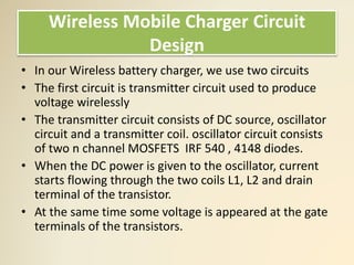
Wireless Mobile Charger Circuit
Design](https://image.slidesharecdn.com/wirelessmobilebatterychargercircuit-170804133538/85/Wireless-mobile-battery-charger-8-320.jpg)