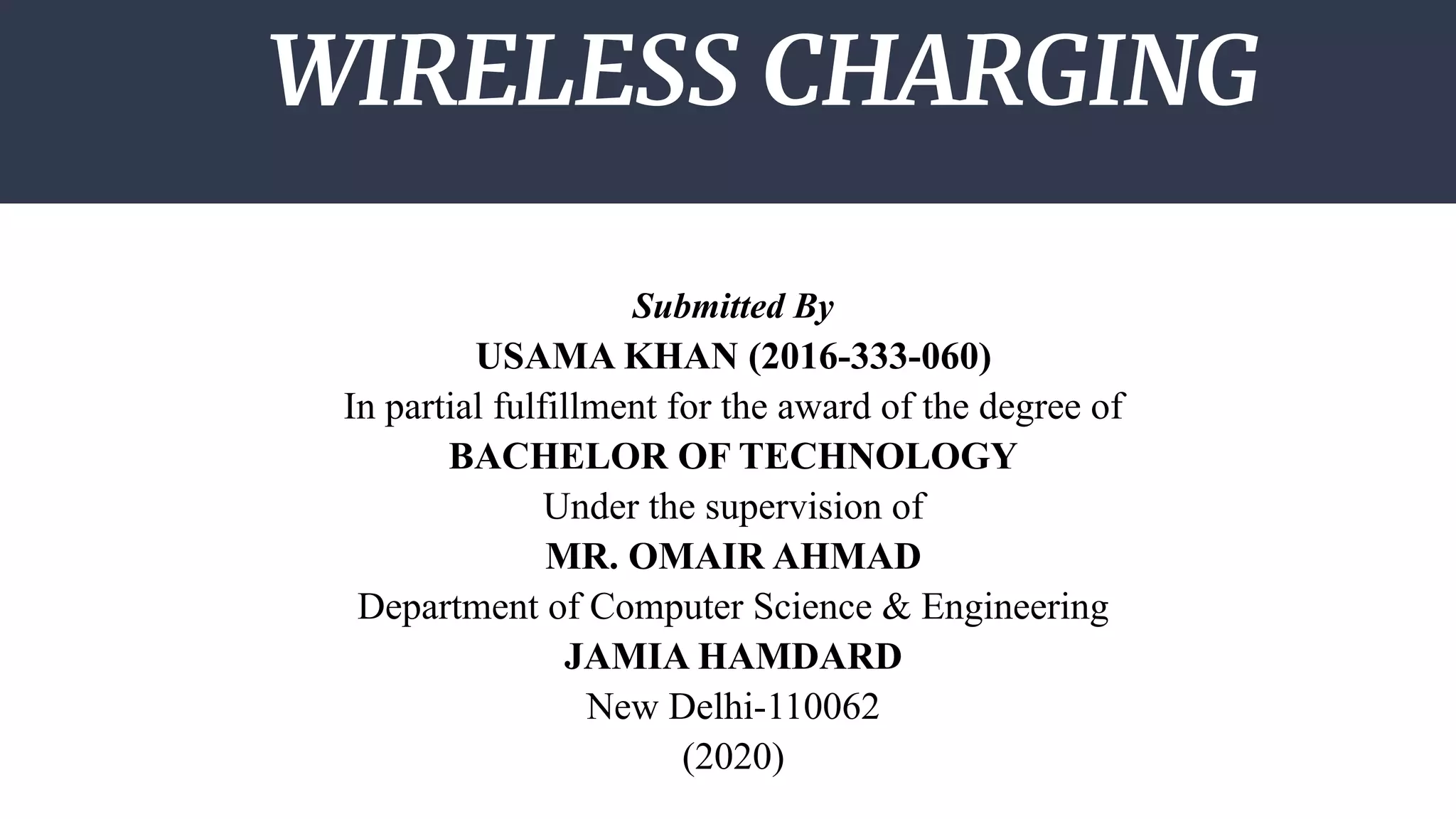
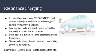
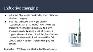
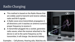
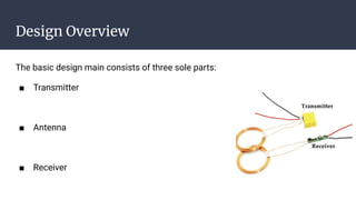
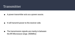
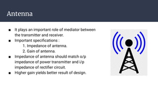
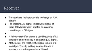
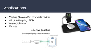
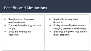
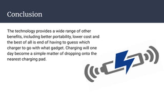
Wireless charging is making inroads in the healthcare, automotive and manufacturing industries because it offers the promise of increased mobility and advances that could allow tiny internet of things (IoT) devices to get power many feet away from a charger.
1. WIRELESS CHARGING
Submitted By
USAMA KHAN (2016-333-060)
In partial fulfillment for the award of the degree of
BACHELOR OF TECHNOLOGY
Under the supervision of
MR. OMAIR AHMAD
Department of Computer Science & Engineering
JAMIA HAMDARD
New Delhi-110062
(2020)
2. CONTENTS
● What is Wireless Charging?
● Types of Charging
● Design Overflow
● Applications
● Benefits and Limitations
● Conclusion
● References
3. What is Wireless Charging?
■ Wireless Charging is one of the several methods of
charging batteries without the use of cable or device
specific AC adaptors.
■ Wireless charging can be used for a wide variety of
devices including cell phones, laptop, computers and
MP3 players as well as larger objects such as robots
and electric cars.
4. Methods of Wireless Charging
There are three types of Wireless Charging : -
■ Resonance Charging
■ Inductive Charging
■ Radio Charging
5. Resonance Charging
■ It uses phenomenon of “RESONANCE”, that
causes an object to vibrate when energy of
certain frequency is applied.
■ Two copper coils are used, one attached to
transmitter & another to receiver.
■ Both coils are tuned to same electromagnetic
frequency.
■ These coils when placed close to one another,
power is transferred.
Examples : - Electric cars, Robots, Computers etc.
6. Inductive charging
■ Inductive Charging is one kind of short distance
wireless charging.
■ This method works on the principle of
“ELECTROMAGNETIC INDUCTION” where the
charger device will create an E.M field with
alternating polarity using a coil of insulated
copper wire & a similar coil will be placed inside
the mobile device which will convert E.M field
back to electric current thereby charging the
battery.
Examples : - MP3 players, Electric toothbrushes etc.
7. Radio Charging
■ This method is based on the Radio Waves that
are widely used to transmit and receive cellular,
radio and Wi-fi signals.
■ A Radio wave once transmitted, propagates in
all directions unit it reaches an antenna tuned to
proper frequency to receive it.
■ A transmitter plugged into a socket, generates
radio waves, when the receiver attached to the
device is set to the same frequency as the
transmitter, it will charge the device’s battery.
Examples : - Cell phones, Hearing aids, Watches etc.
8. Design Overview
The basic design main consists of three sole parts:
■ Transmitter
■ Antenna
■ Receiver
9. Transmitter
■ A power transmitter acts as a power source.
■ It will transmit power to the receiver side.
■ The transmission signals are mainly in between
the RF/Microwave range. (900Mhz)
10. Antenna
■ It plays an important role of mediator between
the transmitter and receiver.
■ Important specifications :
1. Impedance of antenna.
2. Gain of antenna.
■ Impedance of antenna should match o/p
impedance of power transmitter and i/p
impedance of rectifier circuit.
■ Higher gain yields better result of design.
11. Receiver
■ The receivers main purpose is to charge an AAA
battery.
■ For charging, AC signal (microwave signal of
value 900Mhz) is taken and fed to a rectifier
circuit to get a DC signal.
■
■ A full-wave rectifier circuit is used because of its
simplicity and efficiency in converting AC signal.
■ At the o/p of the rectifier, the signal is not a DC
signal yet. Thus by adding a capacitor and a
resistor a smooth o/p can be achieved.
13. Benefits and Limitations
➢ Simultaneous charging of
multiple devices.
➢ The way the technology works is
simple.
➢ Since it is wireless it is
economic.
➢ Applicable for only short
distances.
➢ For big devices like electric cars,
charging stations may be limited.
➢ Efficiency and power loss are the
major problems.
14. Conclusion
The technology provides a wide range of other
benefits, including better portability, lower cost and
the best of all is end of having to guess which
charger to go with what gadget. Charging will one
day become a simple matter of dropping onto the
nearest charging pad.
15. References
■ Espejel.J.D, “RF to DC power generation”,
University of Maryland, December 2003.
■ http://drum.umd.edu:8003/dspace/handle/190
3/173
■ Electronics today magazine, June 2008 issue,
page no 63-66.
■ www.howdostuffwork.com
■ www.whatis.com