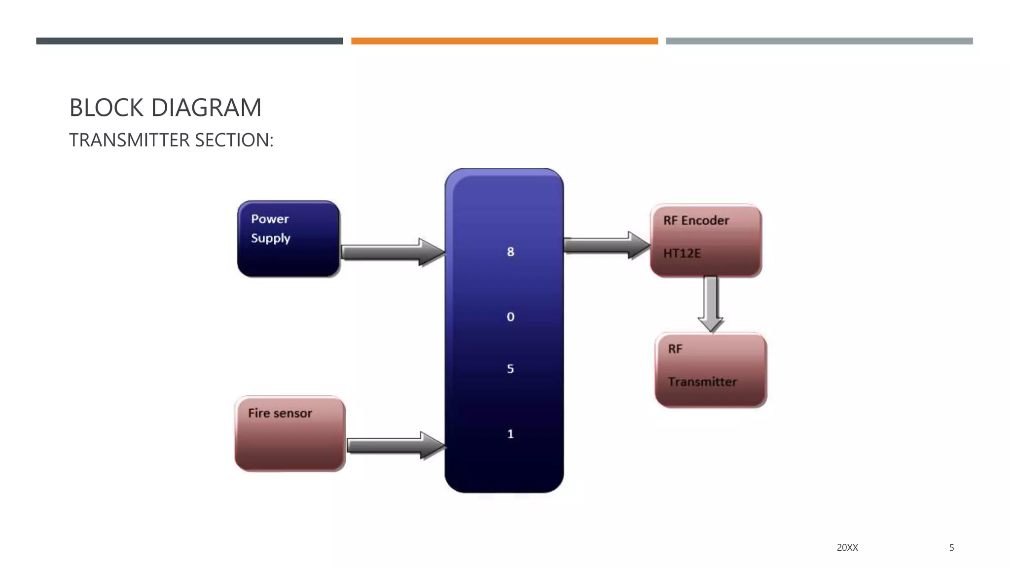
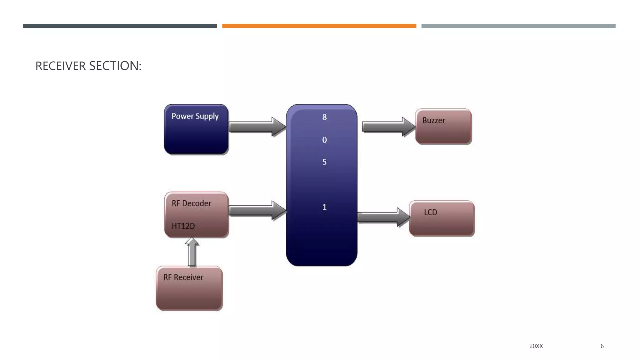
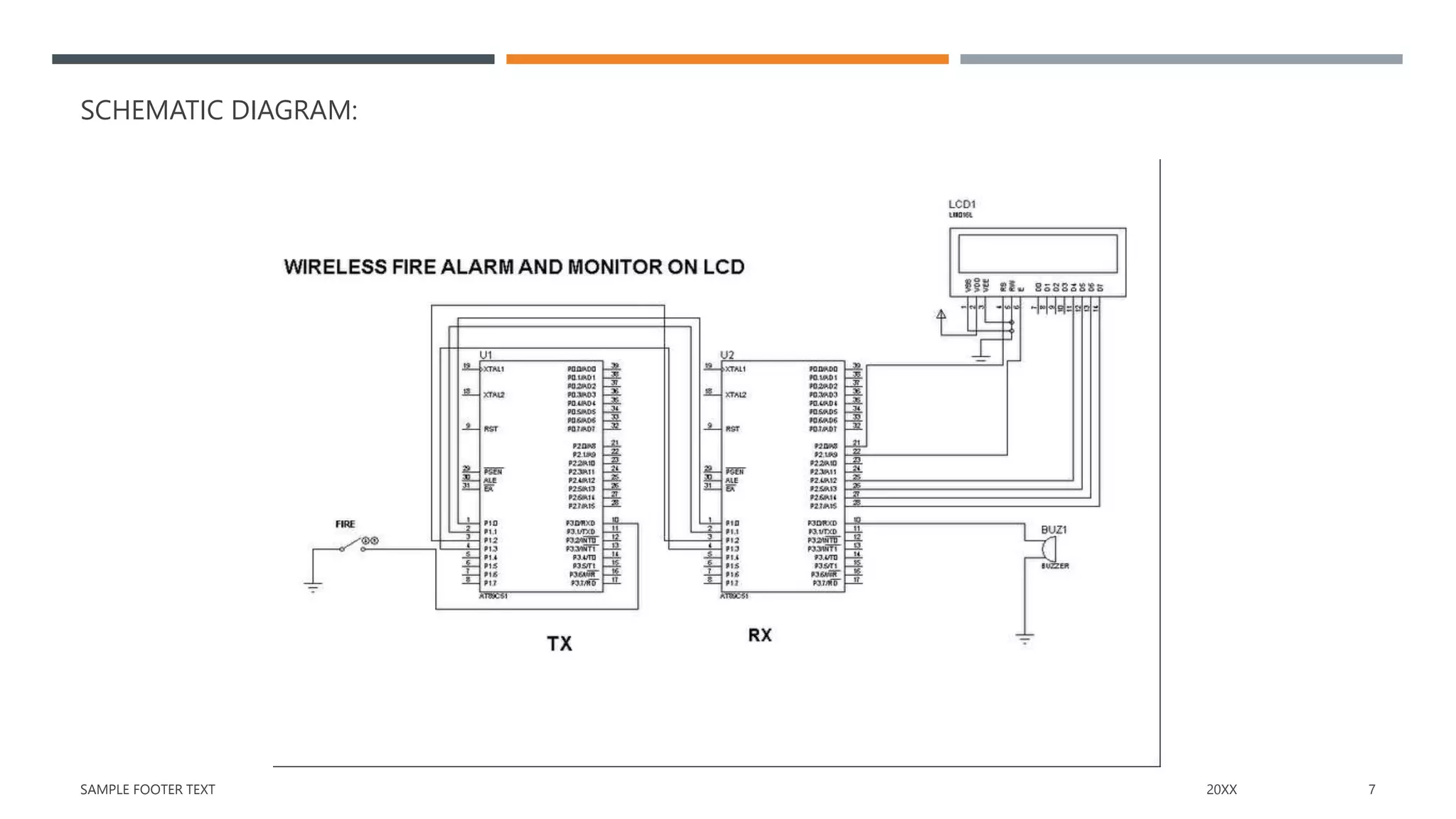
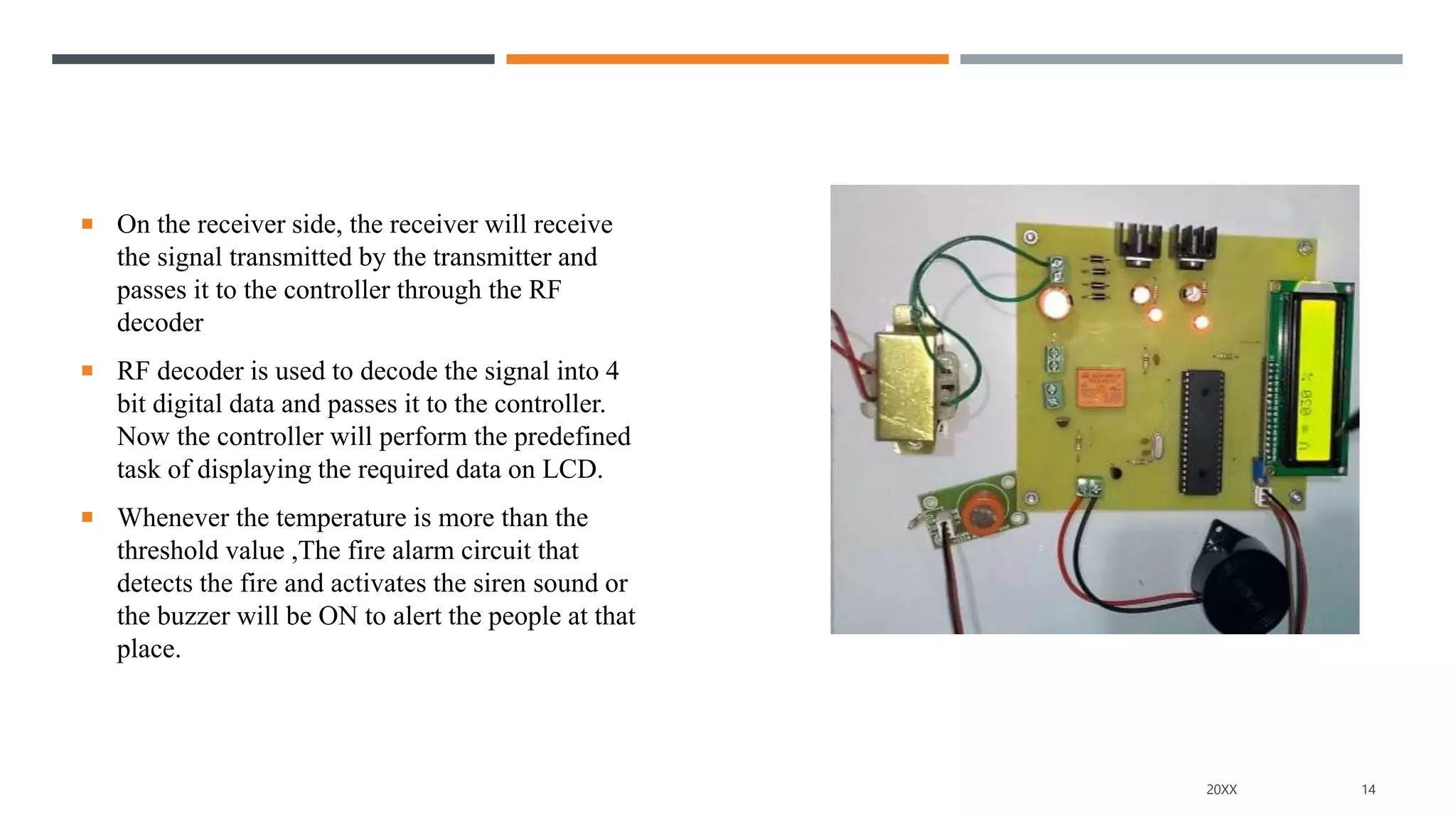
WIRELESS FIRE ALARM & MONITOR ON LCD
PROJECT GUIDE PROJECT BY
B.SWAPNA P.THIRUPATHI REDDY (20W95A0285)
P.UDAYKIRAN (20W95A0286)
V.NAGAMANOHAR (20W95A02B1)
P.VENKATESHWARLU (20W95A0281)
CONTENTS
1. Abstract
2. Objective
3. Block diagram
4. Hardware required
5. Software required
6. Applications
7. Working
8. Pros and Cons
9. Conclusion
2
ABSTRACT
 The main aim/purpose of this project is to continuously monitor the house or industries, if any fire accident
occurs, by using wireless monitoring technology. It do the early detection of fire apart from preventive measures to
reduce the losses due to hazardous fire.
 Fires usually occur in homes due to inattention and changes in environmental conditions. They cause threats to the
residential community and may lead to human death and property damage. Thus, house fires must be detected as
early as possible to prevent these types of threats.
 This study provides a simple design for a wireless fire detection network system. This system is meant to notify
the household of a fire occurrence in the house by displaying a message on LCD and alert the people by buzzer by
giving audio signal as output.
 Here the wireless communication between the remote areas can be achieved by using the RF modules called RF
transmitter and RF receiver. This project is designed in such a way that the controller will be interfaced to the fire
sensor as well to the RF transmitter through an RF encoder.
20XX 3
OBJECTIVE
 The main objective of this project is to make a wireless fire alarm & monitoring system, it really can be
the difference between life and death. Having one installed at your business premise dramatically improves
your safety as it can alert you to the presence of a fire as soon as it starts.
1. Reduced wiring
2. Reduced cost
3. Real-time monitoring
4. Fast operation
5. Easy maintenance.
20XX 4
BLOCK DIAGRAM
TRANSMITTER SECTION:
20XX 5
RECEIVER SECTION:
20XX 6
SCHEMATIC DIAGRAM:
SAMPLE FOOTER TEXT 20XX 7
HARDWARE REQUIRED
Fire sensor
 Operating voltage: 3.3V to 5V
 Adjustable detection range,Fast response Time.
 Detection angle about 60 degrees, it is sensitive to the flame spectrum.
Crystal oscillator
 Operating frequency: 11.0592MHz
 Operating Temperature Range: -20 to + 70°C
 Storage Temperature Range: -55 to + 125°C
 Consists of automatic amplitude control
 Stability in frequency
 Easy of interfacing, Small in size & low cost
8
MICROCONTROLLER (AT89S52)
 microcontroller is available in 40 pin Dual Inline package (DIP).
All these 40 pins perform different functions like read, write,
interrupts, I/O operations, address etc. 8051 microcontroller have
four I/O ports (Port-1, Port-2, Port-3, Port-4 ) where in each port
has 8 pin.
 Therefore, out of 40 pins, 32 pins are allotted for I/O port. The
remaining pins are assigned to VCC, GND, XTAL1, XTAL2,
RST, ALE, EA’ and PSEN’.
 The AT89S52 is an 16-bit microcontroller from the Atmel family.
 It is a 40 pin ic package
 4kb Internal ROM flash memory
 256 byte internal RAM memory.
 We are using a pair of identical AT89S52 microcontrollers as
UART Infrastructure. The UART interface consists of two pins:
the Rx and Tx pin. The Rx pin is used to receive data. The Tx pin
is used to transmit data.
9
Buzzer
 Operating Voltage: 5V
 Frequency: 3300Hz
 Current: <15mA
 Polarity: Positive PIN marked on the surface
Voltage regulator (7805)
 Requires very minimum external components to fully function
 It can deliver up to 1.5 A of current (with heat sink).
 Has both internal current limiting and thermal shutdown features
 7805 is a three terminal device with the three pins being 1. INPUT,
2. GROUND and 3. OUTPUT
 Pin 1 is the INPUT Pin. A positive unregulated voltage is given as
input to this pin.
 Pin 2 is the GROUND Pin. It is common to both Input and Output.
 Pin 3 is the OUTPUT Pin. The output regulated 5V is taken at this
pin of the IC.
10
LCD display
 The LCD can be made in large sizes of over 60 inch or 150 cm
diagonal.
 It has no geometric distortion.
 It is very compact, thin, and light CRT displays.
 It does not affect by the magnetic fields.
 Due to low power consumption, small heat emitted during operation.
 It is much thinner than a CRT (cathode ray tube) monitor.
Stepdown Transformer(12V)
 Input Voltage 230V AC
 Output Voltage 12V DC
 Output Current 2 Amp
 100% Copper Winding Vertical mount type transformer
11
SOFTWARE REQUIRED
1. KEIL Micro vision IDE for Programming.
2. Proteus Professional for Designing.
3. UC Flash
APPLICATIONS
1. Industrial applications
2. Security applications
20XX 12
WORKING
 This project is mainly designed to protect the industrial
equipments like machinery and to alert the people in
surroundings
 The project mainly consists of Stepdown Transformer(230V AC-
12V DC), Fire sensor, Microcontroller(AT89S52), RF receiver,
RF transmitter, RF encoder, RF decoder, LCD, Buzzer, Voltage
Regulator and Filter.
 We will use Pair of 8051 Family microcontrollers in this project.
 This project is designed in such a way that the controller will be
interfaced to the fire sensor as well to the RF transmitter through
an RF encoder.
 The RF encoder is used to encode the data received by the
controller. The controller continuously monitor the fire sensor
and transmits the corresponding signal if the fire is detected.
13
 On the receiver side, the receiver will receive
the signal transmitted by the transmitter and
passes it to the controller through the RF
decoder
 RF decoder is used to decode the signal into 4
bit digital data and passes it to the controller.
Now the controller will perform the predefined
task of displaying the required data on LCD.
 Whenever the temperature is more than the
threshold value ,The fire alarm circuit that
detects the fire and activates the siren sound or
the buzzer will be ON to alert the people at that
place.
20XX 14
PROS AND CONS OF WIRELESS FIRE ALARMS
Pros
 Wireless fire alarms are easy to install anywhere
 Wireless fire alarms are easy to modify
 Wireless fire alarms will work if the power goes out
 Early warning benefits
 High level security and low power consumption
Cons
 Wireless fire alarms have range restrictions
 Wireless fire alarms require batteries
 Continuous power supply required
20XX 15
CONCLUSION
 The main purpose /aim of this project is to protect the house & industrial system
using sensors like Temperature(fire sensor) and monitors on lcd.
 The wireless fire alarm system using sensors is a system designed to protect
industries from losses due to fire accidents using dual microcontrollers.
 The system monitors and senses the room temperature to detect the fire, avoid any
industrial accidents and prevent losses.
20XX 16
0XX

WIRELESS FIRE ALARM & MONITOR ON LCD

  • 1.
    WIRELESS FIRE ALARM& MONITOR ON LCD PROJECT GUIDE PROJECT BY B.SWAPNA P.THIRUPATHI REDDY (20W95A0285) P.UDAYKIRAN (20W95A0286) V.NAGAMANOHAR (20W95A02B1) P.VENKATESHWARLU (20W95A0281)
  • 2.
    CONTENTS 1. Abstract 2. Objective 3.Block diagram 4. Hardware required 5. Software required 6. Applications 7. Working 8. Pros and Cons 9. Conclusion 2
  • 3.
    ABSTRACT  The mainaim/purpose of this project is to continuously monitor the house or industries, if any fire accident occurs, by using wireless monitoring technology. It do the early detection of fire apart from preventive measures to reduce the losses due to hazardous fire.  Fires usually occur in homes due to inattention and changes in environmental conditions. They cause threats to the residential community and may lead to human death and property damage. Thus, house fires must be detected as early as possible to prevent these types of threats.  This study provides a simple design for a wireless fire detection network system. This system is meant to notify the household of a fire occurrence in the house by displaying a message on LCD and alert the people by buzzer by giving audio signal as output.  Here the wireless communication between the remote areas can be achieved by using the RF modules called RF transmitter and RF receiver. This project is designed in such a way that the controller will be interfaced to the fire sensor as well to the RF transmitter through an RF encoder. 20XX 3
  • 4.
    OBJECTIVE  The mainobjective of this project is to make a wireless fire alarm & monitoring system, it really can be the difference between life and death. Having one installed at your business premise dramatically improves your safety as it can alert you to the presence of a fire as soon as it starts. 1. Reduced wiring 2. Reduced cost 3. Real-time monitoring 4. Fast operation 5. Easy maintenance. 20XX 4
  • 5.
  • 6.
  • 7.
  • 8.
    HARDWARE REQUIRED Fire sensor Operating voltage: 3.3V to 5V  Adjustable detection range,Fast response Time.  Detection angle about 60 degrees, it is sensitive to the flame spectrum. Crystal oscillator  Operating frequency: 11.0592MHz  Operating Temperature Range: -20 to + 70°C  Storage Temperature Range: -55 to + 125°C  Consists of automatic amplitude control  Stability in frequency  Easy of interfacing, Small in size & low cost 8
  • 9.
    MICROCONTROLLER (AT89S52)  microcontrolleris available in 40 pin Dual Inline package (DIP). All these 40 pins perform different functions like read, write, interrupts, I/O operations, address etc. 8051 microcontroller have four I/O ports (Port-1, Port-2, Port-3, Port-4 ) where in each port has 8 pin.  Therefore, out of 40 pins, 32 pins are allotted for I/O port. The remaining pins are assigned to VCC, GND, XTAL1, XTAL2, RST, ALE, EA’ and PSEN’.  The AT89S52 is an 16-bit microcontroller from the Atmel family.  It is a 40 pin ic package  4kb Internal ROM flash memory  256 byte internal RAM memory.  We are using a pair of identical AT89S52 microcontrollers as UART Infrastructure. The UART interface consists of two pins: the Rx and Tx pin. The Rx pin is used to receive data. The Tx pin is used to transmit data. 9
  • 10.
    Buzzer  Operating Voltage:5V  Frequency: 3300Hz  Current: <15mA  Polarity: Positive PIN marked on the surface Voltage regulator (7805)  Requires very minimum external components to fully function  It can deliver up to 1.5 A of current (with heat sink).  Has both internal current limiting and thermal shutdown features  7805 is a three terminal device with the three pins being 1. INPUT, 2. GROUND and 3. OUTPUT  Pin 1 is the INPUT Pin. A positive unregulated voltage is given as input to this pin.  Pin 2 is the GROUND Pin. It is common to both Input and Output.  Pin 3 is the OUTPUT Pin. The output regulated 5V is taken at this pin of the IC. 10
  • 11.
    LCD display  TheLCD can be made in large sizes of over 60 inch or 150 cm diagonal.  It has no geometric distortion.  It is very compact, thin, and light CRT displays.  It does not affect by the magnetic fields.  Due to low power consumption, small heat emitted during operation.  It is much thinner than a CRT (cathode ray tube) monitor. Stepdown Transformer(12V)  Input Voltage 230V AC  Output Voltage 12V DC  Output Current 2 Amp  100% Copper Winding Vertical mount type transformer 11
  • 12.
    SOFTWARE REQUIRED 1. KEILMicro vision IDE for Programming. 2. Proteus Professional for Designing. 3. UC Flash APPLICATIONS 1. Industrial applications 2. Security applications 20XX 12
  • 13.
    WORKING  This projectis mainly designed to protect the industrial equipments like machinery and to alert the people in surroundings  The project mainly consists of Stepdown Transformer(230V AC- 12V DC), Fire sensor, Microcontroller(AT89S52), RF receiver, RF transmitter, RF encoder, RF decoder, LCD, Buzzer, Voltage Regulator and Filter.  We will use Pair of 8051 Family microcontrollers in this project.  This project is designed in such a way that the controller will be interfaced to the fire sensor as well to the RF transmitter through an RF encoder.  The RF encoder is used to encode the data received by the controller. The controller continuously monitor the fire sensor and transmits the corresponding signal if the fire is detected. 13
  • 14.
     On thereceiver side, the receiver will receive the signal transmitted by the transmitter and passes it to the controller through the RF decoder  RF decoder is used to decode the signal into 4 bit digital data and passes it to the controller. Now the controller will perform the predefined task of displaying the required data on LCD.  Whenever the temperature is more than the threshold value ,The fire alarm circuit that detects the fire and activates the siren sound or the buzzer will be ON to alert the people at that place. 20XX 14
  • 15.
    PROS AND CONSOF WIRELESS FIRE ALARMS Pros  Wireless fire alarms are easy to install anywhere  Wireless fire alarms are easy to modify  Wireless fire alarms will work if the power goes out  Early warning benefits  High level security and low power consumption Cons  Wireless fire alarms have range restrictions  Wireless fire alarms require batteries  Continuous power supply required 20XX 15
  • 16.
    CONCLUSION  The mainpurpose /aim of this project is to protect the house & industrial system using sensors like Temperature(fire sensor) and monitors on lcd.  The wireless fire alarm system using sensors is a system designed to protect industries from losses due to fire accidents using dual microcontrollers.  The system monitors and senses the room temperature to detect the fire, avoid any industrial accidents and prevent losses. 20XX 16
  • 17.