Wireless facsimile connectivity using gsm module
•
1 like•75 views

Abstract Wireless Communication is being one of the modern trends of communication which is mostly nowadays implemented everywhere. We have been doing our industry defined problem based on wireless communication at Doordarshan High Power Transmitter (H.P.T.) Vadodara. During our training period we have found the problem of no wires connection between D.M.C Vadodara and H.P.T. station at Waghodia. We will be solving the problem by establishing “WIRELESS FASCIMILE CONNECTIVITY”. Our aim is to create device that interface with Fax Machine with the help of GSM network.

Recommended
More Related Content
What's hot
What's hot (20)
Viewers also liked
Viewers also liked (6)
Similar to Wireless facsimile connectivity using gsm module
Similar to Wireless facsimile connectivity using gsm module (20)
More from eSAT Journals
More from eSAT Journals (20)
Recently uploaded
Recently uploaded (20)
Wireless facsimile connectivity using gsm module
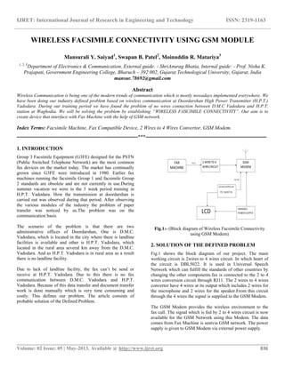
- 1. IJRET: International Journal of Research in Engineering and Technology ISSN: 2319-1163 __________________________________________________________________________________________ Volume: 02 Issue: 05 | May-2013, Available @ http://www.ijret.org 836 WIRELESS FACSIMILE CONNECTIVITY USING GSM MODULE Mansurali Y. Saiyad1 , Swapan B. Patel2 , Moinuddin R. Matariya3 1, 2, 3 Department of Electronics & Communication, External guide: - ShriAnurag Bhatia, Internal guide: - Prof. Nisha K. Prajapati, Government Engineering College, Bharuch – 392 002, Gujarat Technological University, Gujarat, India mansur.78692@gmail.com Abstract Wireless Communication is being one of the modern trends of communication which is mostly nowadays implemented everywhere. We have been doing our industry defined problem based on wireless communication at Doordarshan High Power Transmitter (H.P.T.) Vadodara. During our training period we have found the problem of no wires connection between D.M.C Vadodara and H.P.T. station at Waghodia. We will be solving the problem by establishing “WIRELESS FASCIMILE CONNECTIVITY”. Our aim is to create device that interface with Fax Machine with the help of GSM network. Index Terms: Facsimile Machine, Fax Compatible Device, 2 Wires to 4 Wires Convertor, GSM Modem. -----------------------------------------------------------------------***----------------------------------------------------------------------- 1. INTRODUCTION Group 3 Facsimile Equipment (G3FE) designed for the PSTN (Public Switched Telephone Network) are the most common fax devices on the market today. The market has continually grown since G3FE were introduced in 1980. Earlier fax machines running the facsimile Group 1 and facsimile Group 2 standards are obsolete and are not currently in use.During summer vacation we were in the 3 week period training in H.P.T. Vadodara. How the transmission at doordarshan is carried out was observed during that period. After observing the various modules of the industry the problem of paper transfer was noticed by us.The problem was on the communication basis. The scenario of the problem is that there are two administrative offices of Doordarshan, One is D.M.C. Vadodara, which is located in the city where there is landline facilities is available and other is H.P.T. Vadodara, which located in the rural area several km away from the D.M.C. Vadodara. And as H.P.T. Vadodara is in rural area as a result there is no landline facility. Due to lack of landline facility, the fax can’t be send or receive at H.P.T. Vadodara. Due to this there is no fax communication between D.M.C. Vadodara and H.P.T. Vadodara. Because of this data transfer and document transfer work is done manually which is very time consuming and costly. This defines our problem. The article consists of probable solution of the Defined Problem. Fig.1:- (Block diagram of Wireless Facsimile Connectivity using GSM Modem) 2. SOLUTION OF THE DEFINED PROBLEM Fig.1 shows the block diagram of our project. The main working circuit is 2wires to 4 wires circuit. In which heart of the circuit is DBL5022. It is used in Universal Speech Network which can fulfill the standards of other countries by changing the other components.fax is connected to the 2 to 4 wires conversion circuit through RJ11. The 2 wires to 4 wires convertor have 4 wires at its output which includes 2 wires for the microphone and 2 wires for the speaker.From this circuit through the 4 wires the signal is supplied to the GSM Modem. The GSM Modem provides the wireless environment to the fax call. The signal which is fed by 2 to 4 wires circuit is now available for the GSM Network using this Modem. The data comes from Fax Machine is sentvia GSM network. The power supply is given to GSM Modem via external power supply.
- 2. IJRET: International Journal of Research in Engineering and Technology ISSN: 2319-1163 __________________________________________________________________________________________ Volume: 02 Issue: 05 | May-2013, Available @ http://www.ijret.org 837 The Microcontroller which we have used is PIC16F877A. This Microcontroller is very versatile as the use of its span is very large. It is connected through its appropriate ports to the GSM Modem via RS232 cable. Microcontroller is used to provide AT commands to the GSM Modem. It also interfaced with the LCD display. It is used to display the incoming and outgoing fax numbers. 3. TIME SEQUENCE OF FAX CALL: Fig.2:- (Time Sequence of fax call) Description of phases: PhaseA – Call establishment: Call establishment can be realized manually and/or automatically. Phase B – Pre-message procedure The pre-message procedure consists of the identification of capabilities and the commanding of the chosen conditions as well as the confirmation of acceptable conditions. When connection is established between terminals Operating in accordance with this recommendation and a terminal operating in a non-ITU-T manner, the terminals should disconnect before the in-message procedure unless both terminals include optional, compatible procedures. Identification section – Capabilities identification; – Confirmation for reception; – Terminal identification (option); – Non-standard facilities identification (option). Command section – Capabilities command; – Training; – Synchronization as well as the following optional commands: – Non-standard facilities command; – Terminal identification command; – Polling (send) command; – Echo suppressor disabling. Fig.3:- (Call Establishment in Automatic manner) Automatic operation at both the calling and called terminals. Figure.3 indicates the actions required by the terminal to establish a call. Phase C1 – In-message procedure The in-message procedure takes place at the same time as message transmission and controls the complete signaling for in-message procedure, e.g., in-message synchronization, error detection and correction and line supervision. Phase C2 – Message transmission The message transmission procedure is about how the facsimile message is transmitted through the transmitter block to the receiver block.
- 3. IJRET: International Journal of Research in Engineering and Technology ISSN: 2319-1163 __________________________________________________________________________________________ Volume: 02 Issue: 05 | May-2013, Available @ http://www.ijret.org 838 Table.1:- Process of automatic Operation of facsimile call Phase D – Post-message procedure The post-message procedure includes information regarding: – End-of-message signaling; – Confirmation signaling; – Multipage signaling; – End-of-facsimile procedure signaling. Phase E – Call release Call release shall be realized manually and/or automatically. 4. FLOW CHART OF WIRELESS FACIMILE CONNECTIVITY PROCESS: Fig.4:- (flow chart of wireless facsimile connectivity process) Fig.4 shows the basic flow chart of wireless facsimile connectivity process. To transmit the fax from H.P.T. to D.M.C., first of all one have to dial the D.M.C. Fax number. And as H.P.T. Fax machine is connected to the microcontroller and the GSM device, Microcontroller will give the required AT Commands to the GSM device for the establishment of communication. Through GSM network the Fax call is connected to BTS and further it is connected to BSC. Again BSC is connected to the MSC. Finally MSC is connected to Public Service Telephone Network (PSTN). And as the Facsimile call is connected to PSTN through PSTN whole telephone network is connected so finally fax can be receive to D.M.C., Vadodara. To receive the fax at H.P.T., one has to dial the H.P.T. Fax number from D.M.C., Vadodara. The facility of landline connection is available at D.M.C. It is directly connected to PSTN and through the PSTN the fax call is hand over to the particular MSC. Through MSC it is further given to the BSC. The BSC gives it to the particular BTS, which will be located near to H.P.T., Vadodara and finally through wireless GSM network between BTS and GSM device the Fax call reaches at H.P.T., Vadodara. In this way finally fax can be received. 5. REQUIREMENT OF TWO WIRES TO FOUR WIRES CIRCUIT: In wireless facsimile connectivity using GSM network, we have to provide the environment for the data to travel from fax machine to GSM modem OR from GSM modem to fax machine .We cannot directly provide the data from fax machine to GSM modem OR from GSM modem to fax machine. It is because of that fax machine sends or receive data via two wires terminals and GSM modem sends or receive data via four wires terminal. Therefore we require a desire interfacing circuit which interfaces between fax machine and GSM modem such that data can be send or receive between these two devices. Call event No. Calling terminal Called terminal 1 2 3 4 5 Terminal detects dial tone and dials desired number (Note). To clearly indicate to a normal telephone user that he is inadvertently connected, CNG will be transmitted to line during the time that signals are attempted to be detected. Begin facsimile procedure. Terminal detects ring and answers the call Optionally, a recorded verbal announcement may be transmitted. Transmit CED. Begin facsimile procedure.
- 4. IJRET: International Journal of Research in Engineering and Technology ISSN: 2319-1163 __________________________________________________________________________________________ Volume: 02 Issue: 05 | May-2013, Available @ http://www.ijret.org 839 Fig.5:- 2 to 4 wires converter circuit using DBL 5022 5.1 INTERFACING SOLUTION: The interfacing problem between fax machine and GSM modem can be overcome by designing such a device which provides two wires environments for the fax machine and four wires environments for GSM modem. This is achieved by the circuit which is called ‘two wires to four wires circuit’. This circuit has four wires at one end and two wires at other end. At the two wires end we can connect fax machine and at four wires end we can connect GSM modem. We can interface these two devices by connecting it at these two ends of the circuit. 5.2 INTERFACING CIRCUIT (TWO WIRES TO FOUR WIRES CIRCUIT) The circuit which provide desire environment for wireless facsimile connectivity is two wires to four wires circuit. This circuit is practically used in PSTN Network. This circuit has four wires at one end and two wires at other end as we have mentioned above. In case of PSTN NETWORK, these two wires are connected with telephone line and four wires of this circuit is connected with speaker and microphone. As shown in figure.5this circuit has two wires terminals which is connected with telephone line. But in our case these two wiresis connected to fax machine from where we send or receive data, and four wires of this circuit is connected with four wires of GSM modem. This circuit works on 12V power supply. This power supply is provided externally along with two wires. This circuit has main IC which is DBL 5022. Entire operation of this circuit is controlled and maintained by this IC. DBL 5022 ICs has 16 pins. Fig.5 shows the detail circuit diagram of 2 wires to 4 wires convertor circuit using DBL 5022. This circuit has the ability to convert the RJ 11 signal into 4 wires which is then given directly to handset of GSM Modem. The internal power supply is given at pin 13 of DBL 5022.Pin 11 and Pin 12 is not used for the application of sending fax but both pin i.e. pin 11 DTMF signal should be kept open and pin 12 is MUTE pin which should be kept HIGH Level to avoid muting of system. CONCLUSIONS As there is lack of wired connection between doordarshan DMC, Vadodara city & HPT, Vadodara with the help of GSM network the problem can be solved. The detail problem in the industry was discussed completely and through our project we have conclude that as there is no landline connection available between D.M.C., Vadodara City and H.P.T., Vadodara, with the help of GSM network the problem can be solved. Until now the paper transfer were done manually which is very cumbersome and time consuming process. With our project, industry of the Doordarshan will get rid of it and it will be now transfer with the help of GSM network. REFERENCES: [1]Theodore S. Rappaport,Wireless Communication: Principles and Practice, Chapter 11, 2nd Edition, Prentice Hall Publication, 2009. [2] ITU-T Recommendation T.4,Standardization of Group 3 facsimile terminals for document transmission, pp.4-5, 2005. [3]ITU-T Recommendation V.8 (2000), Procedures for starting sessions of data transmission over the general switched telephone network. [4]ITU-T Recommendation V.34 (1998), a modem operating at data signaling rates of up to 33 600 bit/s for use on the general switched telephone network and on leased point-to- point 2-wires telephone-type circuits. [5] Datasheet of DBL 5022, datasheet archive [6]David Benson, PIC Technologies, PIC Controller Operation guide [7]Michaelpredco,Programming and customizing the PIC microcontroller. RJ 11 Connecter from FAX To Handset ofGSM Modem
- 5. IJRET: International Journal of Research in Engineering and Technology ISSN: 2319-1163 __________________________________________________________________________________________ Volume: 02 Issue: 05 | May-2013, Available @ http://www.ijret.org 840 [8] John B.Peatman ,Design with PIC microcontroller BIOGRAPHIES ShriAnurag Bhatiareceived hisBSC physics Degree from APS University, Rewa and AMIETE from New Delhi. He has been as Engineering Assistant of DMC Vadodara from 2006. Nisha K. Prajapati received her M.E. Degree from L.D. College of Engineering in 2007. From May 2011, she has been a faculty member of Electronics & Communication Engineering in Government Engineering College, Bharuch, Gujarat, India. Her areas of interests are in Wireless Communication, Microcontroller and Interfacing, and Digital Communication. Mansurali Y. Saiyad (090140111013) is pursuing B.E. Electronics & Communication Engineering from GEC, Bharuch and presently he is working on his project under guidance of ShriAnurag Bhatiaand Professor Nisha K. Prajapati. Swapan B. Patel(090140111018)is pursuing B.E. Electronics & Communication Engineering from GEC, Bharuch and presently he is working on his project under guidance of ShriAnurag Bhatiaand Professor Nisha K. Prajapati. Moinuddin R. Matariya (090140111031)is pursuing B.E. Electronics & Communication Engineering from GEC, Bharuch and presently he is working on his project under guidance of ShriAnurag Bhatiaand Professor Nisha K. Prajapati.