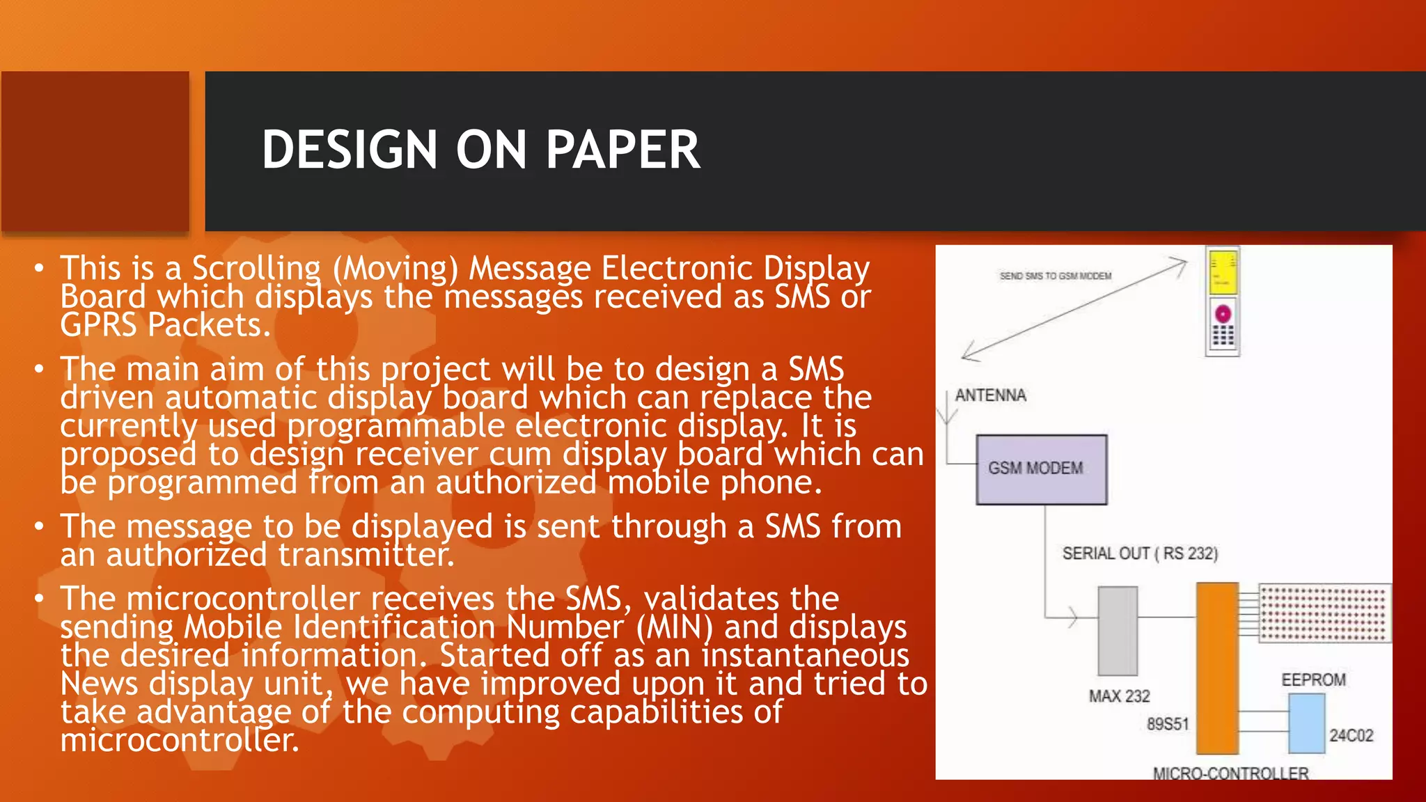
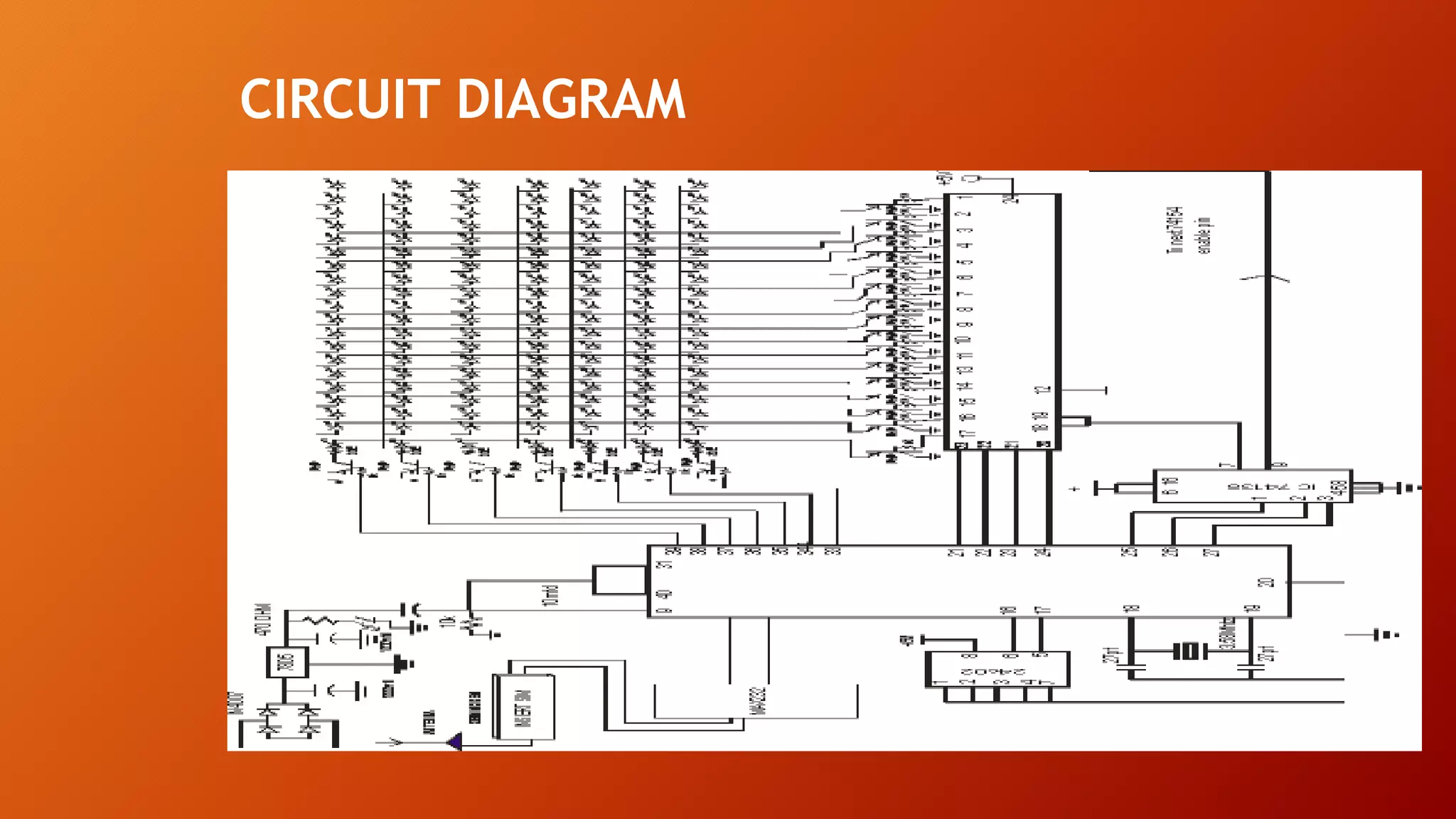
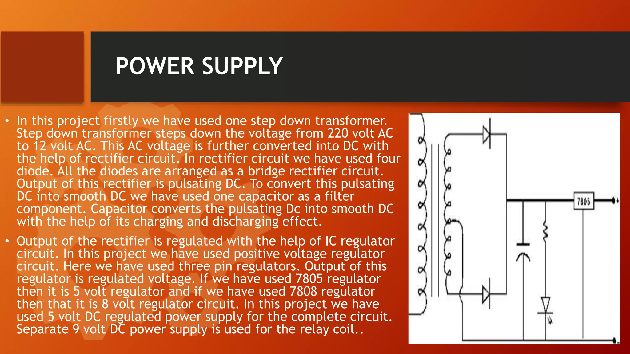
New from BookNet Canada for 2024: BNC CataList - Tech Forum 2024
Â
Smart led display boards
1. Smart LEDDisplay Boards
Submitted to the Department of Electronics and
communication Engineering in partial fulfillment of the
requirements for the award of the degree of
BACHELOR OF TECHNOLOGY
in
Electronics and Communication Engineering
of
Biju Patnaik University of Technology, Odisha
2. Smart LED Display Boards
⢠Submitted by
PRADEEP SATNAMI - Reg.No:1601204078
CHUMKI SETHI - Reg.No:1721204002
SAROJA KUMAR SAHU - Reg.No:1601204068
⢠Under the Guidance of --
Prof.(Er) Partha Sarathi Padhy
Associate Professor in
Department of Electronics and Communication Engineering
3. Contents
⢠INTRODUCTON
⢠GSM
⢠SUBSCRIBER IDENTETY MODULE (SIM)
⢠LED
⢠DESIGN ON PAPER
⢠CIRCUIT DIAGRAM
⢠POWER SUPPLY
⢠HARDWARE PROFILE
⢠SOFTWARE
⢠MICROCONTROLLER
⢠CONCLUSION
⢠FUTURE WORK
4. INTRODUCTION
The led Display System is aimed at the colleges and universities for displaying
day- to-day information continuously or at regular intervals during the working
hours. Being GSM- based system, it offers flexibility to display flash news or
announcements faster than the programmable system. GSM-based display system
can also be used at other public places like schools, hospitals, railway stations,
gardens etc. It presents an SMS based display board incorporating the widely used
GSM to facilitate the communication of displaying message on display board via
userâs mobile phone from any part of the world.
5. GSM
⢠GSM (Global System for Mobile Communications, originally Group Special Mobile), is a standard developed by
the European Telecommunications Standards Institute (ETSI) to describe protocols for second generation (2G)
digital cellular networks used by mobile phones.
⢠It is the de facto global standard for mobile communications with over 90% market share, and is available in
over 219 countries and territories
⢠The GSM standard was developed as a replacement for first generation (1G) analog cellular networks, and
originally described a digital, circuit-switched network optimized for full duplex voice telephony.
⢠This was expanded over time to include data communications, first by circuit-switched transport, then
packet data transport via GPRS and EDGE. "GSM" is a trademark owned by the GSM Association.
⢠It may also refer to the initially most common voice codec used, Full Rate. Regardless of the frequency
selected by an operator, it is divided into timeslots for individual phones.
⢠This allows eight full-rate or sixteen half-rate speech channels per radio frequency.
⢠These eight radio timeslots (or burst periods) are grouped into a TDMA frame. Half- rate channels use
alternate frames in the same timeslot.
⢠The channel data rate for all 8 channels is 270. 833 Kbit/s, and the frame duration is 4. 615 ms. the
transmission power in the handset is limited to a maximum of 2 watts in GSM 850/900 and 1 watt in GSM
1800/1900.
6. SUBSCRIBER IDENTETY MODULE (SIM)
⢠One of the key features of GSM is the Subscriber Identity Module,
commonly known as a SIM card. The SIM is a detachable smart card
containing the user's subscription information and phone book.
This allows the user to retain his or her information after
switching handsets. Alternatively, the user can also change
operators while retaining the handset simply by changing the SIM.
Some operators will block this by allowing the phone to use only a
single SIM, or only a SIM issued by them; this practice is known as
SIM locking.
7. LED
⢠A light-emitting diode (LED) is a two-lead semiconductor light source that resembles a basic
pin-junction diode, except that an LED also emits light. When an LED's anode lead has a
voltage that is more positive than its cathode lead by at least the LED's forward voltage
drop, current flows.
⢠Electrons are able to recombine with holes within the device, releasing energy in the form
of photons. This effect is called electroluminescence, and the colour of the light
(corresponding to the energy of the photon) is determined by the energy band gap of the
semiconductor. An LED is often small in area (less than 1 mm2), and integrated optical
components may be used to shape its radiation pattern. Appearing as practical electronic
components in 1962, the earliest LEDs emitted low-intensity infrared light. Infrared LEDs
are still frequently used as transmitting elements in remote-control circuits, such as those
in remote controls for a wide variety of consumer electronics.
⢠The first visible-light LEDs were also of low intensity, and limited to red. Modern LEDs are
available across the visible, ultraviolet, and infrared wavelengths, with very high
brightness. Early LEDs were often used as indicator lamps for electronic devices, replacing
small incandescent bulbs. They were soon packaged into numeric readouts in the form of
seven-segment displays, and were commonly seen in digital clocks. Recent developments in
LEDs permit them to be used in environmental and task lighting. LEDs have many
advantages over incandescent light sources including lower energy consumption, longer
lifetime, improved physical robustness, smaller size, and faster switching. Light-emitting
diodes are now used in applications as diverse as aviation lighting, automotive headlamps,
advertising, general, traffic signals, and camera flashes. However, LEDs powerful enough for
room lighting are still relatively expensive, and require more precise current and heat
management than compact fluorescent lamp sources of comparable output. LEDs have
allowed new text, video displays, and sensors to be developed, while their high switching
rates are also useful in advanced communications technology.
8. DESIGN ON PAPER
⢠This is a Scrolling (Moving) Message Electronic Display
Board which displays the messages received as SMS or
GPRS Packets.
⢠The main aim of this project will be to design a SMS
driven automatic display board which can replace the
currently used programmable electronic display. It is
proposed to design receiver cum display board which can
be programmed from an authorized mobile phone.
⢠The message to be displayed is sent through a SMS from
an authorized transmitter.
⢠The microcontroller receives the SMS, validates the
sending Mobile Identification Number (MIN) and displays
the desired information. Started off as an instantaneous
News display unit, we have improved upon it and tried to
take advantage of the computing capabilities of
microcontroller.
10. POWER SUPPLY
⢠In this project firstly we have used one step down transformer.
Step down transformer steps down the voltage from 220 volt AC
to 12 volt AC. This AC voltage is further converted into DC with
the help of rectifier circuit. In rectifier circuit we have used four
diode. All the diodes are arranged as a bridge rectifier circuit.
Output of this rectifier is pulsating DC. To convert this pulsating
DC into smooth DC we have used one capacitor as a filter
component. Capacitor converts the pulsating Dc into smooth DC
with the help of its charging and discharging effect.
⢠Output of the rectifier is regulated with the help of IC regulator
circuit. In this project we have used positive voltage regulator
circuit. Here we have used three pin regulators. Output of this
regulator is regulated voltage. If we have used 7805 regulator
then it is 5 volt regulator and if we have used 7808 regulator
then that it is 8 volt regulator circuit. In this project we have
used 5 volt DC regulated power supply for the complete circuit.
Separate 9 volt DC power supply is used for the relay coil..
11. HARDWARE PROFILE
AT89S51 Microcontroller
⢠Low-power, high-performance CMOS 8-bit microcontroller
with 4KB of ISP flashes memory. The device uses Atmel
high-density, non-volatile memory technology and is
compatible with the industry-standard 80C51 instruction
set and pin-out. On-chip flash allows program memory to
be reprogrammed in-system or by a conventional non-
volatile memory programmer.
12. ⢠Compatible with MCSŽ-51 Products
⢠4K Bytes of In-System Programmable (ISP) Flash Memory
⢠Endurance: 10, 000 Write/Erase Cycles
⢠4. 0V to 5. 5V Operating Range
⢠Fully Static Operation: 0 Hz to 33 MHz
⢠Three-level Program Memory Lock
⢠128 x 8-bit Internal RAM
⢠32 Programmable I/O Lines
⢠Two 16-bit Timer/Counters
⢠Six Interrupt Sources
⢠Full Duplex UART Serial Channel
⢠Low-power Idle and Power-down Modes
⢠Interrupt Recovery from Power-down Mode
⢠Watchdog Timer
⢠Dual Data Pointer
⢠Power-off Flag
⢠Fast Programming Time
⢠Flexible ISP Programming (Byte and Page Mode)
Features
13. GSM Module
⢠It is used to establish communication between a computer and a GSM-GPRS
system. Global System for Mobile communication (GSM) is an architecture used
for mobile communication in most of the countries.
⢠Global Packet Radio Service (GPRS) is an extension of GSM that enables higher
data transmission rate. GSM/GPRS module consists of a GSM/GPRS modem
assembled together with power supply circuit and communication interfaces (like
RS-232, USB, etc) for computer.
⢠The MODEM is the soul of such modules. GSM/GPRS MODEM is a class of wireless
MODEM devices that are designed for communication of a computer with the GSM
and GPRS network. It requires a SIM (Subscriber Identity Module) card just like
mobile phones to activate communication with the network. Also they have IMEI
(International Mobile Equipment Identity) number similar to mobile phones for
their identification. A GSM/GPRS MODEM can perform the following operations:
⢠Receive, send or delete SMS messages in a SIM.
⢠Read, add, search phonebook entries of the SIM.
⢠Make, Receive, or reject a voice call.
14. LED Display
⢠Main logic of the moving display is the scanning
process. In the scanning process first of all, we transfer
the data on the microcontroller output (port p0) and
then switch on the first line of the 32 lines matrix.
Switching of LED lines from right to left is very fast,
approx 50 ms speed. With the help of this great speed
LEDs lines are on/off step by step. Due to persistence
of vision, it is not possible to detect the on/off period
of LED lines with the help of naked eyes
16. Programming
⢠Kiel. The Kiel C51 C Compiler for the 8051 microcontroller is the most
popular 8051 C compiler in the world. It provides more features than
any other 8051 C compiler available today.
⢠The C51 Compiler allows you to write 8051 microcontroller
applications in C that, once compiled, have the efficiency and speed of
assembly language. Language extensions in the C51 Compiler give you
full access to all resources of the 8051.
⢠The C51 Compiler translates C source files into reloadable object
modules which contain full symbolic information for debugging with
the ÂľVision Debugger or an in-circuit emulator. In addition to the
object file, the compiler generates a listing file which may optionally
include symbol table and cross reference information
17. Simulation
⢠Proteus. Proteus is software for microprocessor simulation, schematic
capture, and printed circuit board (PCB) design.
⢠It is developed by Lab center Electronics. The X Game Station Micro
Edition was designed using Lab center's Proteus schematic entry and
PCB layout tools. Proteus PCB design combines the ISIS schematic
capture andARES PCB layout programs to provide a powerful,
integrated and easy to use suite of tools for professional PCB Design..
All Proteus PCB design products include an integrated shape based
auto router and a basic SPICE simulation capability as standard. More
advanced routing modes are included in Proteus PCB Design Level 2
and higher whilst simulation capabilities can be enhanced by
purchasing the Advanced Simulation option and/or micro-controller
simulation capabilities. The products are offered at a number of levels
which offer increasing levels of functionality and design capacity
18. MICROCONTROLLER
⢠The MAX232 is an IC, first created in 1987 by Maxim Integrated Products,
that converts signals from an RS-232 serial port to signals suitable for use in
TTL compatible digital logic circuits. The MAX232 is a dual driver/receiver
and typically converts the RX, TX, CTS and RTS signals.
⢠The drivers provide RS-232 voltage level outputs (approx. ¹ 7. 5 V) from a
single + 5 V supply via on-chip charge pumps and external capacitors. This
makes it useful for implementing RS-232 in devices that otherwise do not
need any voltages outside the 0 V to + 5 V range, as power supply design
does not need to be made more complicated just for driving the RS-232 in
this case. The receivers reduce RS-232 inputs (which may be as high as Âą 25
V), to standard 5 V TTL levels.
⢠These receivers have a typical threshold of 1. 3 V, and a typical hysteresis
of 0. 5 V. The MAX232 (A) has two receivers (converts from RS- 232 to TTL
voltage levels), and two drivers (converts from TTL logic to RS-232 voltage
levels). This means only two of the RS-232 signals can be converted in each
direction. Typically, a pair of a driver/receiver of the MAX232 is used for TX
and RX signals, and the second one for CTS and RTS signals.
19. CONCLUSION
The prototype of the GSM based display was efficiently
designed. This prototype has facilities to be integrated with a
display board thus making it truly mobile. It accepts the SMS,
stores it, validates it and then displays it in the LED module.
The SMS is deleted from the SIM each time it is read, thus
making room for the next SMS. Only one SMS can be displayed
at a time. These limitations can be removed by the use of
higher end microcontrollers and extended RAM. The prototype
can be implemented using commercial display boards. In this
case, it can solve the problem of instant information transfer.
20. FUTURE WORK
⢠The use of microcontroller in place of a general purpose computer allows us to theorize on many further
improvements on this project prototype. Temperature display during periods wherein no message buffers are
empty is one such theoretical improvement that is very possible. The ideal state of the microcontroller is when
the indices or storage space in the SIM memory are empty and no new message is there to
â˘
⢠display. With proper use of interrupt routines the incoming message acts as an interrupt, the temperature display
is halted and the control flow jumps over to the specific interrupt service routine which first validates the
senderâs number and then displays the information field.
⢠Another very interesting and significant improvement would be to accommodate multiple receiver MODEMS at the
different positions in a geographical area carrying duplicate SIM cards. With the help of principles of TDMA
technique, we can choose to simulcast and broadcast important notifications. After a display board receives the
valid message through the MODEM and displays it, it withdraws its identification from the network and
synchronously another nearby MODEM signs itself into the network and starts to receive the message. The
message is broadcast by the mobile switching centre for a continuous time period during which as many possible
display board MODEMS âcatchâ the message and display it as per the constraint of validation.
⢠Multilingual display can be another added variation of the project. The display boards are one of the single most
important media for information transfer to the maximum number of end users. This feature can be added by
programming the 40 microcontroller to use different encoding decoding schemes in different areas as per the
local language. This will ensure the increase in the number of informed users. Graphical display can also be
considered as a long term but achievable and target able output. MMS technology along with relatively high end
microcontrollers to carry on the tasks of graphics encoding and decoding along with a more expansive bank of
usable memory can make this task a walk in the park.