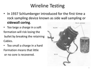
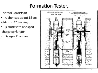
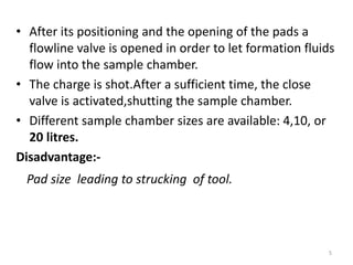
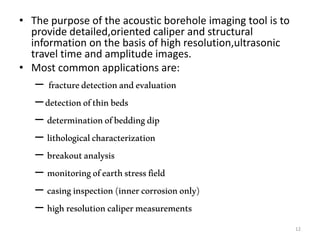
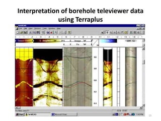
Wireline Sampling and Borehole
Imaging
Presented By:
Jarugula Bhavya Sri
KLUniversity,Petroleum Engineering Dpt,Green Fields,Vaddeswaram,Guntur
1
INDEX
• Wireline Testing
FT(Formation Tester)
FIT (Formation Interval Tester)
RFT(Repeat Formation Tester).
• Borehole imaging
 BHTV(Borehole Televiewer)
2
Wireline Testing
• In 1937 Schlumberger introduced for the first time a
rock sampling device known as side wall sampling or
sidewall coring.
• Too large a charge in a soft
formation will risk losing the
bullet by breaking the retaining
Cables.
• Too small a charge in a hard
Formation means that little
or no core is recovered.
3
Formation Tester.
The tool Consists of
• rubber pad about 15 cm
wide and 70 cm long .
• a block with a shaped
charge perforator.
• Sample Chamber.
4
• After its positioning and the opening of the pads a
flowline valve is opened in order to let formation fluids
flow into the sample chamber.
• The charge is shot.After a sufficient time, the close
valve is activated,shutting the sample chamber.
• Different sample chamber sizes are available: 4,10, or
20 litres.
Disadvantage:-
Pad size leading to strucking of tool.
5
Formation Interval Tester
• Principle and working are
same as FT
Modifications made are:
a smaller pad
(FT pad is relatively large)
6
7Formation tester Formation Interval Tester
Repeat Formation Tester
• The preceeding tools allow only one sample to be collected
and one pressure test to be made on each descent in the
hole.
• For additional tests – cleaning,emptying,replacing.
(Eventually leading to loss of rig time).
1. In one trip in the hole it is possible to set the
2. tool any number of times and take a formation pressure
measurement.
3. Precision on measurement is high.
4. An internal filter prevents sand flow and fluid loss.
5. Pretest of formation can be done to choose permeable zone.
6. Anti-sticking pads practically eliminate the chance of rool
strucking.
8
Borehole Images
• Map of a property around borehole wall(open hole)
• Could be aquired by wireline or LWD .
• Also known as ALT(Advance Log Technique).
Wireline LWD
1.Microresistivity 1.Microresistivity
2.Ultrasonic 2.density
3.photoelectric factor
4.sonic velocities
5.ultrasonic caliper.
9
Advantages
• High vertical resolution.
• Low cost (compared to coring).
• Can run in long section of borehole.
• Used to obtain structural sedimentary ,petrophysical
information.
Challenges
• Manual interpretation of images may take away from
hours to days.
• Most of the texture images seen on the images is
harder to quantify and a detailed textural analysis may
take days.
10
BHTV
• 1969 by mobil oil company.
• Acoustic borehole scanner tools generate an
image of the borehole wall by transmitting
ultrasound pulses from a rotating sensor and
recording the amplitude and travel time of the
signal reflected at the interface between mud
and formation (borehole wall).
• In other words it is known as BAT(Borehole
Acoustic Televiewer).
11
• The purpose of the acoustic borehole imaging tool is to
provide detailed,oriented caliper and structural
information on the basis of high resolution,ultrasonic
travel time and amplitude images.
• Most common applications are:
– fracturedetectionandevaluation
–detectionofthinbeds
– determinationofbeddingdip
– lithologicalcharacterization
– breakoutanalysis
– monitoringofearthstressfield
– casinginspection(innercorrosiononly)
– highresolutioncalipermeasurements
12
Interpretation of borehole televiewer data
using Terraplus
13
14

Wire line sampling

  • 1.
    Wireline Sampling andBorehole Imaging Presented By: Jarugula Bhavya Sri KLUniversity,Petroleum Engineering Dpt,Green Fields,Vaddeswaram,Guntur 1
  • 2.
    INDEX • Wireline Testing FT(FormationTester) FIT (Formation Interval Tester) RFT(Repeat Formation Tester). • Borehole imaging  BHTV(Borehole Televiewer) 2
  • 3.
    Wireline Testing • In1937 Schlumberger introduced for the first time a rock sampling device known as side wall sampling or sidewall coring. • Too large a charge in a soft formation will risk losing the bullet by breaking the retaining Cables. • Too small a charge in a hard Formation means that little or no core is recovered. 3
  • 4.
    Formation Tester. The toolConsists of • rubber pad about 15 cm wide and 70 cm long . • a block with a shaped charge perforator. • Sample Chamber. 4
  • 5.
    • After itspositioning and the opening of the pads a flowline valve is opened in order to let formation fluids flow into the sample chamber. • The charge is shot.After a sufficient time, the close valve is activated,shutting the sample chamber. • Different sample chamber sizes are available: 4,10, or 20 litres. Disadvantage:- Pad size leading to strucking of tool. 5
  • 6.
    Formation Interval Tester •Principle and working are same as FT Modifications made are: a smaller pad (FT pad is relatively large) 6
  • 7.
  • 8.
    Repeat Formation Tester •The preceeding tools allow only one sample to be collected and one pressure test to be made on each descent in the hole. • For additional tests – cleaning,emptying,replacing. (Eventually leading to loss of rig time). 1. In one trip in the hole it is possible to set the 2. tool any number of times and take a formation pressure measurement. 3. Precision on measurement is high. 4. An internal filter prevents sand flow and fluid loss. 5. Pretest of formation can be done to choose permeable zone. 6. Anti-sticking pads practically eliminate the chance of rool strucking. 8
  • 9.
    Borehole Images • Mapof a property around borehole wall(open hole) • Could be aquired by wireline or LWD . • Also known as ALT(Advance Log Technique). Wireline LWD 1.Microresistivity 1.Microresistivity 2.Ultrasonic 2.density 3.photoelectric factor 4.sonic velocities 5.ultrasonic caliper. 9
  • 10.
    Advantages • High verticalresolution. • Low cost (compared to coring). • Can run in long section of borehole. • Used to obtain structural sedimentary ,petrophysical information. Challenges • Manual interpretation of images may take away from hours to days. • Most of the texture images seen on the images is harder to quantify and a detailed textural analysis may take days. 10
  • 11.
    BHTV • 1969 bymobil oil company. • Acoustic borehole scanner tools generate an image of the borehole wall by transmitting ultrasound pulses from a rotating sensor and recording the amplitude and travel time of the signal reflected at the interface between mud and formation (borehole wall). • In other words it is known as BAT(Borehole Acoustic Televiewer). 11
  • 12.
    • The purposeof the acoustic borehole imaging tool is to provide detailed,oriented caliper and structural information on the basis of high resolution,ultrasonic travel time and amplitude images. • Most common applications are: – fracturedetectionandevaluation –detectionofthinbeds – determinationofbeddingdip – lithologicalcharacterization – breakoutanalysis – monitoringofearthstressfield – casinginspection(innercorrosiononly) – highresolutioncalipermeasurements 12
  • 13.
    Interpretation of boreholeteleviewer data using Terraplus 13
  • 14.