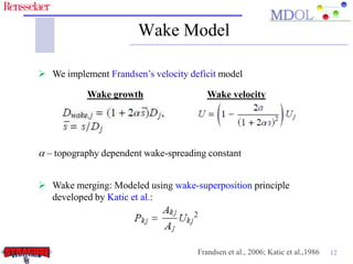
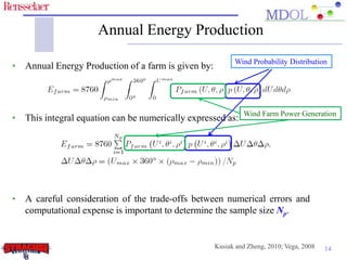
Developing a Flexible Platform for Optimal
                   Engineering Design of
                 Commercial Wind Farms

    Souma Chowdhury*, Jie Zhang*, Achille Messac#, and Luciano Castillo*
#   Syracuse University, Department of Mechanical and Aerospace Engineering
* Rensselaer Polytechnic Institute, Department of Mechanical, Aerospace, and Nuclear Engineering


      ASME 2011 5th International Conference on Energy Sustainability & 9th Fuel
      Cell Science, Engineering and Technology Conference

                                      August 7 – 10, 2011
                                    Grand Hyatt Washington
                                       Washington, DC
Wind Farm Optimization
 Farm Layout Planning: The net power generated by a wind farm is reduced
  by the wake effects, which can be offset by optimizing the farm layout.

 Turbine Type Selection: Optimally selecting the turbine-type(s) to be installed
  can further improve the power generation capacity and the economy of a wind
  farm.

 Wind Distribution Modeling: In order to accurately quantify the energy
  production from a wind farm, it also becomes critically important to
  efficiently determine the expected long-term distribution of wind conditions
  and integrate it within the optimization model.

                Turbine

 Rated      Rotor       Hub      Power
 Power     Diameter    Height    Curve


                                                     www.wind-watch.org        2
Motivation
 Farm Layout Planning: The net power generated by a wind farm is reduced
  by the wake effects, which can be offset by optimizing the farm layout.

 Turbine Type Selection: Optimally selecting the turbine-type(s) to be
  installed can further improve the power generation capacity and the economy
  of a wind farm.

 Wind Distribution Modeling: In order to accurately quantify the energy
  production from a wind farm, it also becomes critically important to
  efficiently determine the expected long-term distribution of wind conditions
  and integrate it within the optimization model.


An effective wind farm optimization method must
  account for the complex interactions among
                these three factors
                                                                            3
Presentation Outline

• Wind Energy and Existing Farm Optimization Methods
• Research Objectives
• Wind Distribution Model
• Power Generation and Turbine Selection Model
• Annual Energy Production and Cost of Energy
• Application of the Wind Farm Optimization Framework
• Concluding Remarks

                                                       4
Wind Energy - Overview
 Currently wind contributes 2.5% of the global electricity consumption.*
 The 2010 growth rate of wind energy has been the slowest since 2004.*
 Large areas of untapped wind potential exist worldwide and in the US.
 Among the factors that affect the growth of wind energy, the state-of-
  the-art in wind farm design technologies plays a prominent role.

 www.prairieroots.org


                             *WWEA, 2011              NREL, 2011      5
Existing Wind Farm Optimization Methods


      Array layout approach                                    Grid based approach
Computationally       less     expensive.            Allows the exploration of different farm
Restricts turbine locating and introduces            configurations.
a source of sub-optimality*                          Results might be undesirably sensitive
                                                     to the pre-defined grid size#

• Do not simultaneously optimize the selection of wind turbines
• Do not consider the joint distribution of wind speed and direction

                                *Sorenson et al., 2006; Mikkelson et al., 2007;
                                #Grady et al., 2005; Sisbot et al., 2009; Gonzleza et al., 2010
                                                                                                  6
Research Objectives:
Unrestricted Wind Farm Layout Optimization (UWFLO)

 Avoid limiting restrictions on the layout pattern of the wind farm.

 Develop a computationally inexpensive analytical power generation
  model and a response surface based wind farm cost (RS-WFC) model.

 Model the use of turbines with differing features and performance
  characteristics.

 Integrate a multivariate and multimodal wind distribution model to
  accurately estimate the AEP and the corresponding COE.

 Maximize the AEP by simultaneously optimizing the farm layout and the
  selection of the turbine-type to be installed. To this end, we apply an
  advanced mixed-discrete PSO algorithm.
        AEP: Annual energy Production; COE: Cost of Energy; PSO: Particle Swarm Optimization
                                                                                               7
Components of the UWFLO framework


                        UWFLO
                       Framework


   Wind          Power
                              Wind Farm    Optimization
Distribution   Generation
                              Cost Model   Methodology
  Model         Model


                                                          8
Wind Distribution Model

In this paper, we use the non-parametric model called the Multivariate and
Multimodal Wind Distribution (MMWD).
• This model is developed using the multivariate Kernel Density
  Estimation (KDE) method.
• This model is uniquely capable of representing multimodally distributed
  wind data.
• This model can capture the joint variations of wind speed, wind direction
  and air density.
• In this paper, we have only used the bivariate version of this model (for
  wind speed and direction)


                                                                              9
Case study

• In this paper, we use 10-year wind data for a class 3 site at Baker, ND*.


• The optimization framework is applied to design a commercial scale 25
  turbine wind farm at this site.

               *N. Dakota agricultural weather network: http://ndawn.ndsu.nodak.edu/
                                                                                       10
UWFLO Power Generation Model
                                Dynamic co-ordinates are assigned to the
                                 turbines based on the direction of wind.

                                Turbine-j is in the influence of the wake
                                 of Turbine-i, if and only if
            Avian Energy, UK


 Effectiveapproach allows us to consider turbines with differing rotor-
   This velocity of wind                   Power generated by Turbine-j:
  approaching Turbine-j:
      diameters and hub-heights


                                                                         11
Wake Model

 We implement Frandsen’s velocity deficit model

           Wake growth                  Wake velocity


a – topography dependent wake-spreading constant


 Wake merging: Modeled using wake-superposition principle
  developed by Katic et al.:


                                     Frandsen et al., 2006; Katic et al.,1986   12
Turbine Selection Model
• Every turbine is defined in terms of its rotor diameter, hub-height, rated
  power, and performance characteristics, and represented by an integer
  code (1 – 66).
• The “power generated vs. wind speed” characteristics for GE 1.5 MW xle
  turbines (ref. turbine) is used to fit a normalized power curve Pn().
• The normalized power curve is scaled back using the rated power and the
  rated, cut-in and cut-out velocities given for each turbine.
                            U  U in 
                           Pn              if U in <U  U r
                               U r  U in 
                      P 
                         1 if U out  U  U r
                      Pr 
                            0 if U  U out
                          
                          
                          
• However, if power curve information is available for all the turbines
  being considered for selection, they can be used directly.

                                                                               13
Annual Energy Production
                                                          Wind Probability Distribution
• Annual Energy Production of a farm is given by:


                                                             Wind Farm Power Generation
• This integral equation can be numerically expressed as:


• A careful consideration of the trade-offs between numerical errors and
  computational expense is important to determine the sample size Np.


                                                    Kusiak and Zheng, 2010; Vega, 2008   14
UWFLO Cost Model

• A response surface based cost model is developed using radial basis
  functions (RBFs).
• The cost in $/per kW installed is expressed as a function of (i) the
  number of turbines (N) in the farm and (ii) the rated power (P) of those
  turbines.
• Data is used from the DOE Wind and Hydropower Technologies
  program to develop the cost model.


                                   Cost farm
                           COE 
                                     AEP
                                                                             15
Problem Definition


                   Farm Boundaries
              Inter-Turbine Spacing
                     COE Constraint


                                      16
Application of the UWFLO Framework

 Case 1: Optimize farm layout for a fixed turbine type (GE 1.5 MW xle)
 Case 2: Optimize the farm layout and the types of the turbines to be
  installed, thereby allowing a combination of multiple turbine types.
 Reference Wind Farm: A 5x5 array layout of GE 1.5 MW xle turbines


Parameter                     Case 1: Fixed         Step 2: Variable      Reference Farm
                              Turbine Type           Turbine Types
Normalized AEP                    0.623                   0.933                    0.597
Overall Farm Efficiency           0.623                   0.635                    0.597
COE ($/kWh)                       0.023                   0.023                    0.024


              66 commercial onshore turbines are used to form the selection pool
                    AEP: Annual energy Production; COE: Cost of Energy                     17
Optimized Layout: Case 1 (Fixed Turbine Type)


                                            18
Optimized Layout: Case 2 (Variable Turbine Types)


                                               19
Concluding Remarks

 We developed a flexible wind farm layout planning framework that
  accounts for the joint variation of wind speed and direction.

 In this framework, wind turbines are allowed to be selected during the
  optimization process.

 Optimally selecting the turbine types produced a farm efficiency 2%
  higher than when a specified wind turbine was used, and a significant 6%
  higher than that produced by array layout-based reference farm.

 Interestingly, we also found that the larger wind turbines (generally with
  higher rated powers) were placed away from the prominent wind directions
  to minimize their shading effects on the other turbines, and their ability to
  be relatively more efficient at lower wind speeds.


                                                                             20
Acknowledgement

• I would like to acknowledge my research adviser
  Prof. Achille Messac, and my co-adviser Prof.
  Luciano Castillo for their immense help and
  support in this research.
• I would also like to thank my friend and colleague
  Jie Zhang for his valuable contributions to this
  paper.


                                                       21
Thank you


 Questions
   and
 Comments


             22
Mixed-Discrete Particle Swarm Optimization (PSO)


 This algorithm has the ability to
  deal with both discrete and
  continuous design variables, and

 The mixed-discrete PSO presents
  an explicit diversity preservation
  capability to prevent premature
  stagnation of particles.

 PSO can appropriately address the
  non-linearity and the multi-
  modality of the wind farm model.


 23

WFO_ES2011_Souma

  • 1.
    Developing a FlexiblePlatform for Optimal Engineering Design of Commercial Wind Farms Souma Chowdhury*, Jie Zhang*, Achille Messac#, and Luciano Castillo* # Syracuse University, Department of Mechanical and Aerospace Engineering * Rensselaer Polytechnic Institute, Department of Mechanical, Aerospace, and Nuclear Engineering ASME 2011 5th International Conference on Energy Sustainability & 9th Fuel Cell Science, Engineering and Technology Conference August 7 – 10, 2011 Grand Hyatt Washington Washington, DC
  • 2.
    Wind Farm Optimization Farm Layout Planning: The net power generated by a wind farm is reduced by the wake effects, which can be offset by optimizing the farm layout.  Turbine Type Selection: Optimally selecting the turbine-type(s) to be installed can further improve the power generation capacity and the economy of a wind farm.  Wind Distribution Modeling: In order to accurately quantify the energy production from a wind farm, it also becomes critically important to efficiently determine the expected long-term distribution of wind conditions and integrate it within the optimization model. Turbine Rated Rotor Hub Power Power Diameter Height Curve www.wind-watch.org 2
  • 3.
    Motivation  Farm LayoutPlanning: The net power generated by a wind farm is reduced by the wake effects, which can be offset by optimizing the farm layout.  Turbine Type Selection: Optimally selecting the turbine-type(s) to be installed can further improve the power generation capacity and the economy of a wind farm.  Wind Distribution Modeling: In order to accurately quantify the energy production from a wind farm, it also becomes critically important to efficiently determine the expected long-term distribution of wind conditions and integrate it within the optimization model. An effective wind farm optimization method must account for the complex interactions among these three factors 3
  • 4.
    Presentation Outline • WindEnergy and Existing Farm Optimization Methods • Research Objectives • Wind Distribution Model • Power Generation and Turbine Selection Model • Annual Energy Production and Cost of Energy • Application of the Wind Farm Optimization Framework • Concluding Remarks 4
  • 5.
    Wind Energy -Overview  Currently wind contributes 2.5% of the global electricity consumption.*  The 2010 growth rate of wind energy has been the slowest since 2004.*  Large areas of untapped wind potential exist worldwide and in the US.  Among the factors that affect the growth of wind energy, the state-of- the-art in wind farm design technologies plays a prominent role. www.prairieroots.org *WWEA, 2011 NREL, 2011 5
  • 6.
    Existing Wind FarmOptimization Methods Array layout approach Grid based approach Computationally less expensive. Allows the exploration of different farm Restricts turbine locating and introduces configurations. a source of sub-optimality* Results might be undesirably sensitive to the pre-defined grid size# • Do not simultaneously optimize the selection of wind turbines • Do not consider the joint distribution of wind speed and direction *Sorenson et al., 2006; Mikkelson et al., 2007; #Grady et al., 2005; Sisbot et al., 2009; Gonzleza et al., 2010 6
  • 7.
    Research Objectives: Unrestricted WindFarm Layout Optimization (UWFLO)  Avoid limiting restrictions on the layout pattern of the wind farm.  Develop a computationally inexpensive analytical power generation model and a response surface based wind farm cost (RS-WFC) model.  Model the use of turbines with differing features and performance characteristics.  Integrate a multivariate and multimodal wind distribution model to accurately estimate the AEP and the corresponding COE.  Maximize the AEP by simultaneously optimizing the farm layout and the selection of the turbine-type to be installed. To this end, we apply an advanced mixed-discrete PSO algorithm. AEP: Annual energy Production; COE: Cost of Energy; PSO: Particle Swarm Optimization 7
  • 8.
    Components of theUWFLO framework UWFLO Framework Wind Power Wind Farm Optimization Distribution Generation Cost Model Methodology Model Model 8
  • 9.
    Wind Distribution Model Inthis paper, we use the non-parametric model called the Multivariate and Multimodal Wind Distribution (MMWD). • This model is developed using the multivariate Kernel Density Estimation (KDE) method. • This model is uniquely capable of representing multimodally distributed wind data. • This model can capture the joint variations of wind speed, wind direction and air density. • In this paper, we have only used the bivariate version of this model (for wind speed and direction) 9
  • 10.
    Case study • Inthis paper, we use 10-year wind data for a class 3 site at Baker, ND*. • The optimization framework is applied to design a commercial scale 25 turbine wind farm at this site. *N. Dakota agricultural weather network: http://ndawn.ndsu.nodak.edu/ 10
  • 11.
    UWFLO Power GenerationModel  Dynamic co-ordinates are assigned to the turbines based on the direction of wind.  Turbine-j is in the influence of the wake of Turbine-i, if and only if Avian Energy, UK  Effectiveapproach allows us to consider turbines with differing rotor-  This velocity of wind  Power generated by Turbine-j: approaching Turbine-j: diameters and hub-heights 11
  • 12.
    Wake Model  Weimplement Frandsen’s velocity deficit model Wake growth Wake velocity a – topography dependent wake-spreading constant  Wake merging: Modeled using wake-superposition principle developed by Katic et al.: Frandsen et al., 2006; Katic et al.,1986 12
  • 13.
    Turbine Selection Model •Every turbine is defined in terms of its rotor diameter, hub-height, rated power, and performance characteristics, and represented by an integer code (1 – 66). • The “power generated vs. wind speed” characteristics for GE 1.5 MW xle turbines (ref. turbine) is used to fit a normalized power curve Pn(). • The normalized power curve is scaled back using the rated power and the rated, cut-in and cut-out velocities given for each turbine.   U  U in   Pn   if U in <U  U r   U r  U in  P   1 if U out  U  U r Pr  0 if U  U out    • However, if power curve information is available for all the turbines being considered for selection, they can be used directly. 13
  • 14.
    Annual Energy Production Wind Probability Distribution • Annual Energy Production of a farm is given by: Wind Farm Power Generation • This integral equation can be numerically expressed as: • A careful consideration of the trade-offs between numerical errors and computational expense is important to determine the sample size Np. Kusiak and Zheng, 2010; Vega, 2008 14
  • 15.
    UWFLO Cost Model •A response surface based cost model is developed using radial basis functions (RBFs). • The cost in $/per kW installed is expressed as a function of (i) the number of turbines (N) in the farm and (ii) the rated power (P) of those turbines. • Data is used from the DOE Wind and Hydropower Technologies program to develop the cost model. Cost farm COE  AEP 15
  • 16.
    Problem Definition Farm Boundaries Inter-Turbine Spacing COE Constraint 16
  • 17.
    Application of theUWFLO Framework  Case 1: Optimize farm layout for a fixed turbine type (GE 1.5 MW xle)  Case 2: Optimize the farm layout and the types of the turbines to be installed, thereby allowing a combination of multiple turbine types.  Reference Wind Farm: A 5x5 array layout of GE 1.5 MW xle turbines Parameter Case 1: Fixed Step 2: Variable Reference Farm Turbine Type Turbine Types Normalized AEP 0.623 0.933 0.597 Overall Farm Efficiency 0.623 0.635 0.597 COE ($/kWh) 0.023 0.023 0.024 66 commercial onshore turbines are used to form the selection pool AEP: Annual energy Production; COE: Cost of Energy 17
  • 18.
    Optimized Layout: Case1 (Fixed Turbine Type) 18
  • 19.
    Optimized Layout: Case2 (Variable Turbine Types) 19
  • 20.
    Concluding Remarks  Wedeveloped a flexible wind farm layout planning framework that accounts for the joint variation of wind speed and direction.  In this framework, wind turbines are allowed to be selected during the optimization process.  Optimally selecting the turbine types produced a farm efficiency 2% higher than when a specified wind turbine was used, and a significant 6% higher than that produced by array layout-based reference farm.  Interestingly, we also found that the larger wind turbines (generally with higher rated powers) were placed away from the prominent wind directions to minimize their shading effects on the other turbines, and their ability to be relatively more efficient at lower wind speeds. 20
  • 21.
    Acknowledgement • I wouldlike to acknowledge my research adviser Prof. Achille Messac, and my co-adviser Prof. Luciano Castillo for their immense help and support in this research. • I would also like to thank my friend and colleague Jie Zhang for his valuable contributions to this paper. 21
  • 22.
    Thank you Questions and Comments 22
  • 23.
    Mixed-Discrete Particle SwarmOptimization (PSO)  This algorithm has the ability to deal with both discrete and continuous design variables, and  The mixed-discrete PSO presents an explicit diversity preservation capability to prevent premature stagnation of particles.  PSO can appropriately address the non-linearity and the multi- modality of the wind farm model. 23

Editor's Notes

  • #6 Slowing down of growth rate might be due to various reasons, such as “limiting Gov. policies”, “lack of development in supporting infrastructure such a gridlines” – all these are restricting the spread of wind energy into the regions that are still untapped.
  • #15 Here we see how the Annual Energy Production depends on the wind distribution p()