This document provides information about plumbing systems, including:
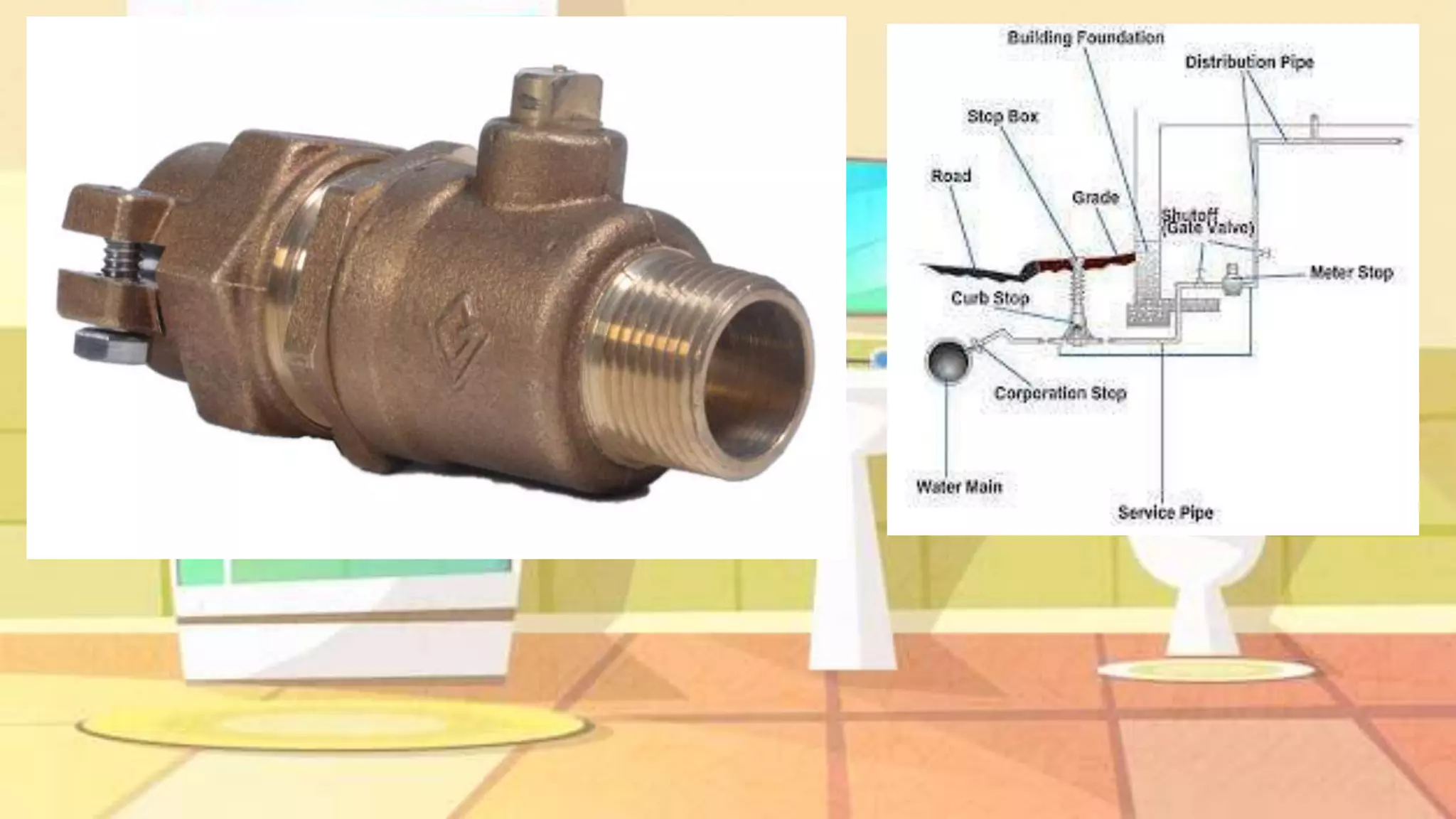
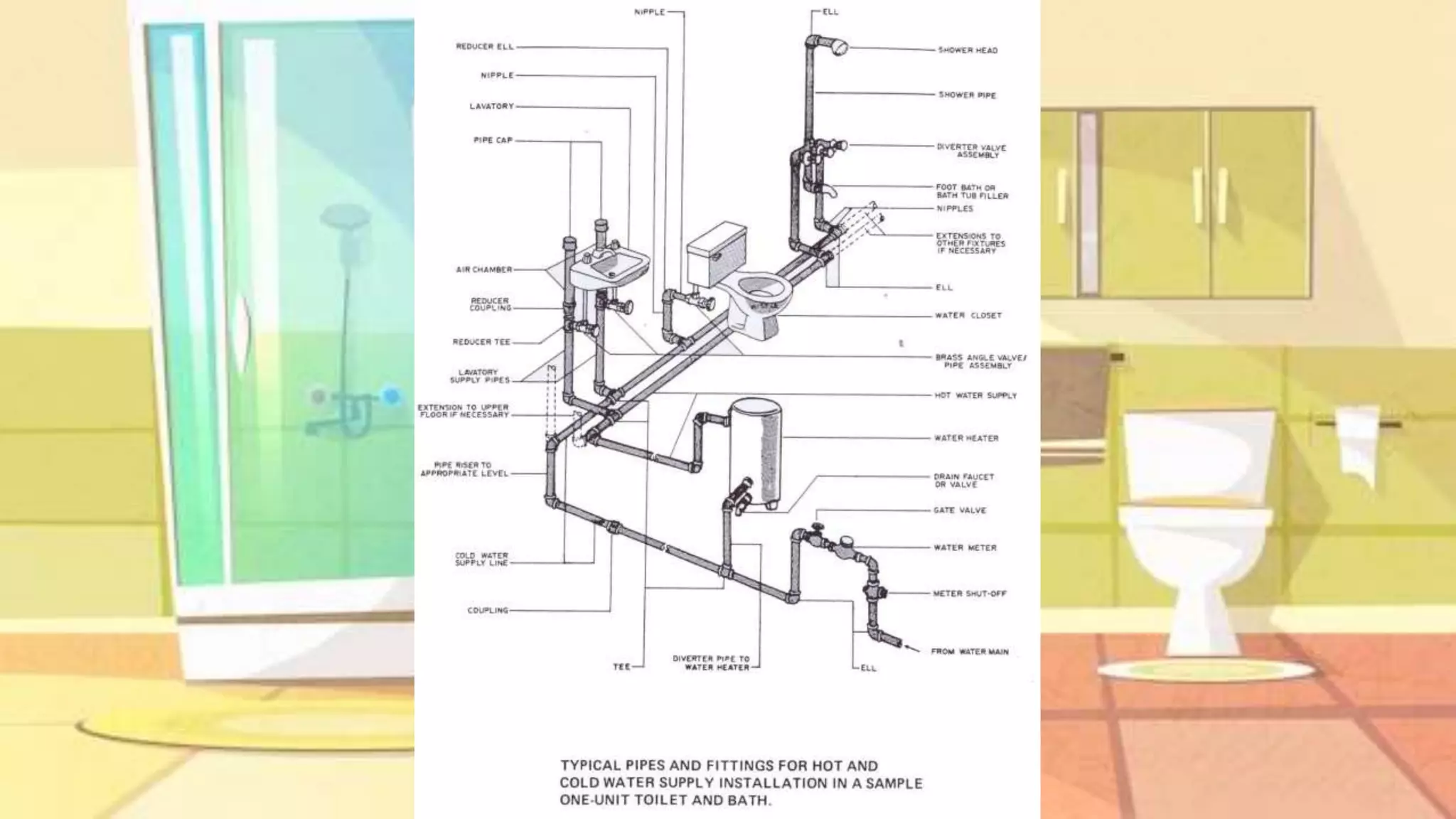
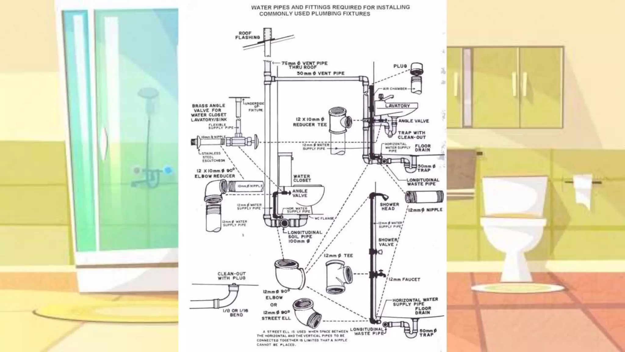
- The water distribution system conveys water through pipes and fittings to sanitary installations, which carry off wastes.
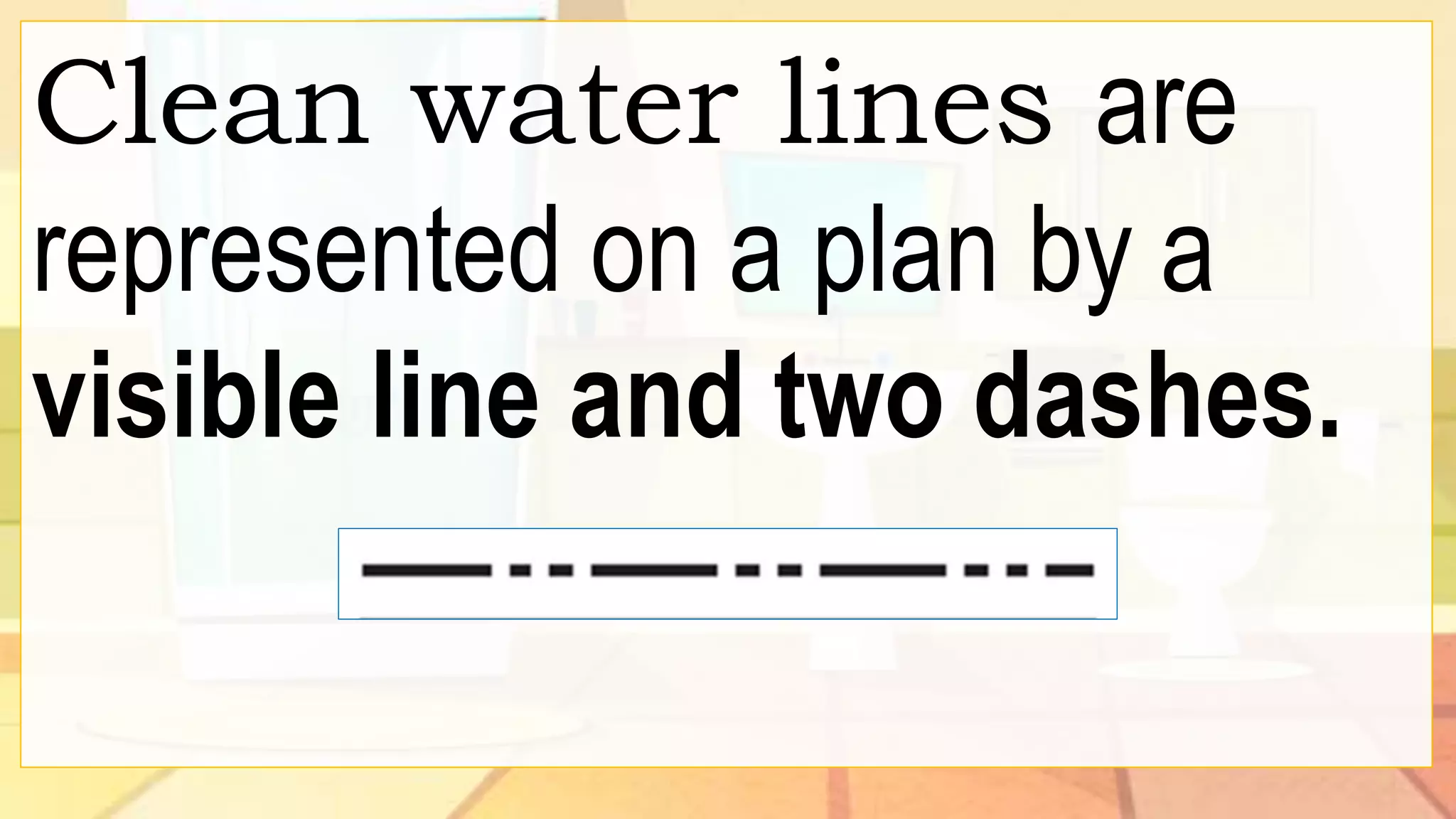
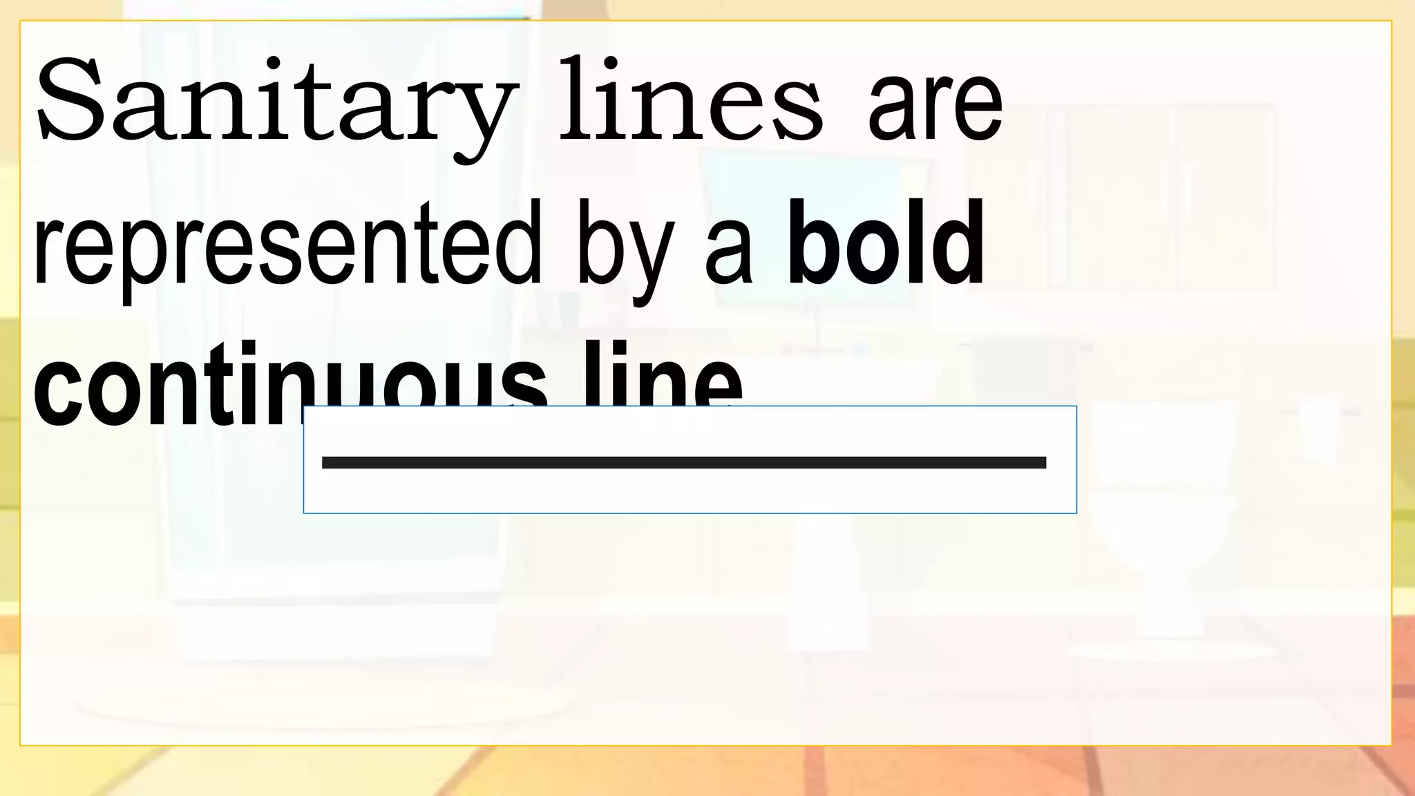
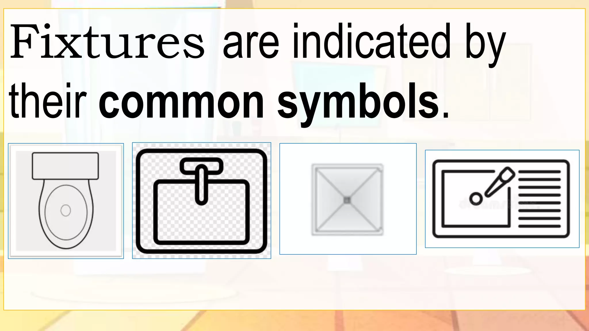
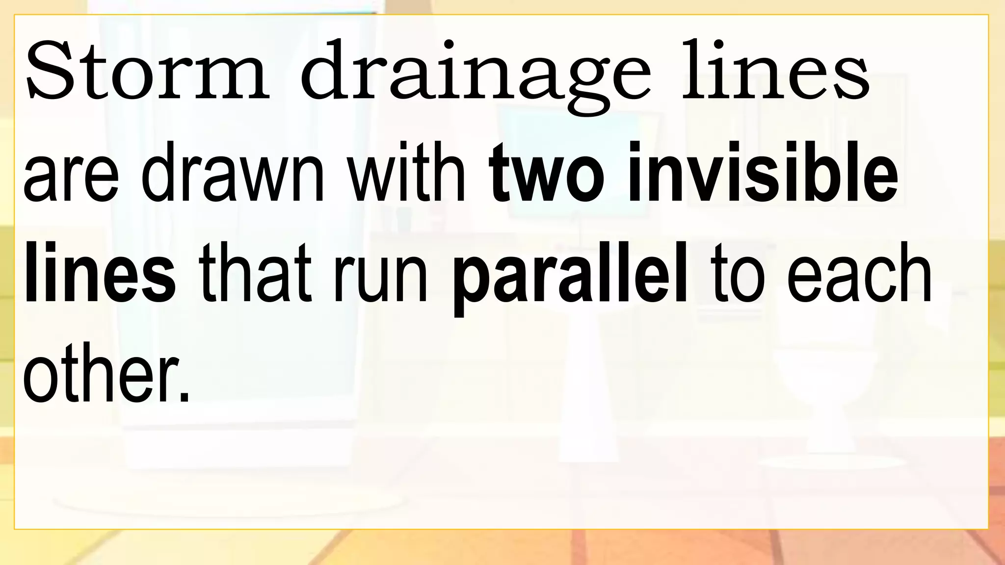
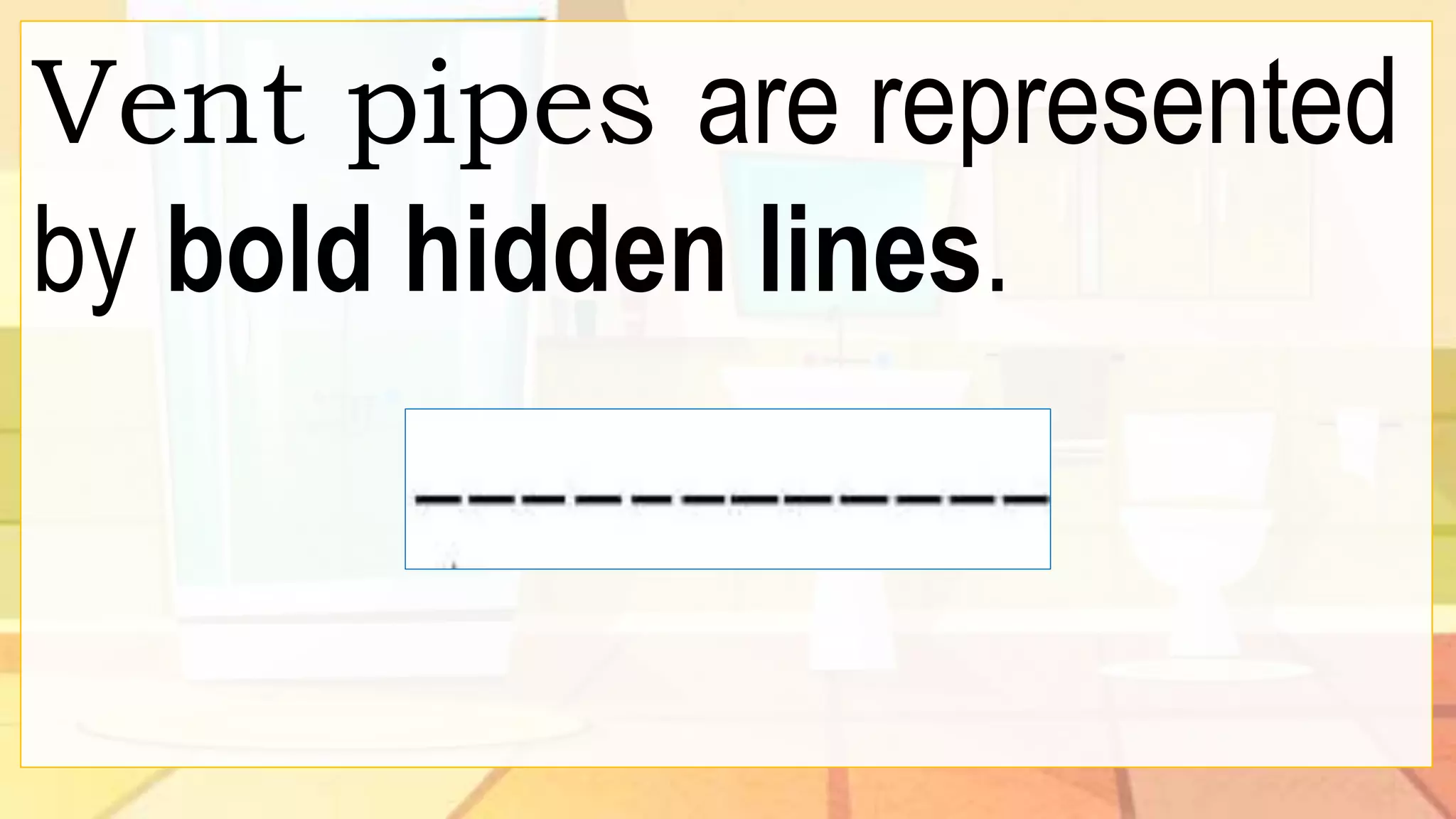
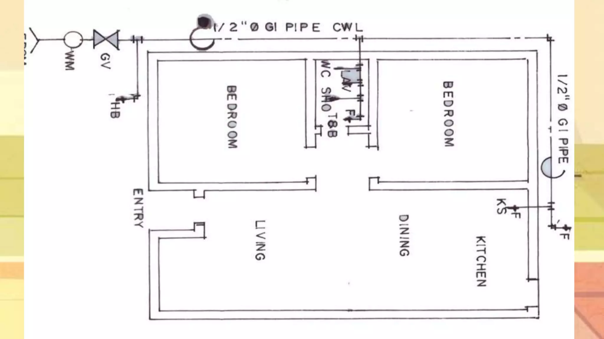
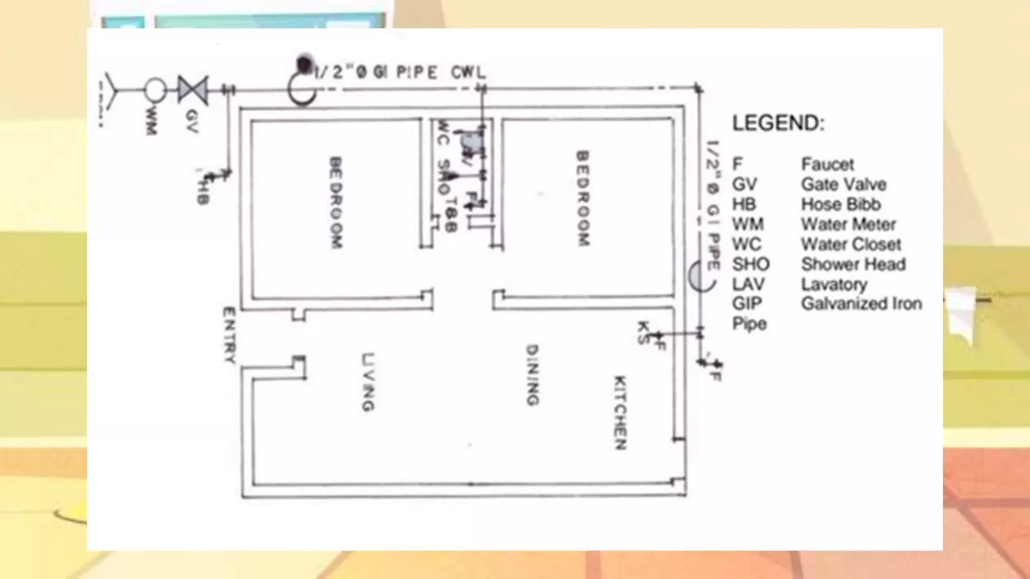
- Clean water lines are represented by a visible line and two dashes on plans, while sanitary lines use a bold continuous line. Fixtures have common symbols and storm drainage uses two invisible parallel lines.
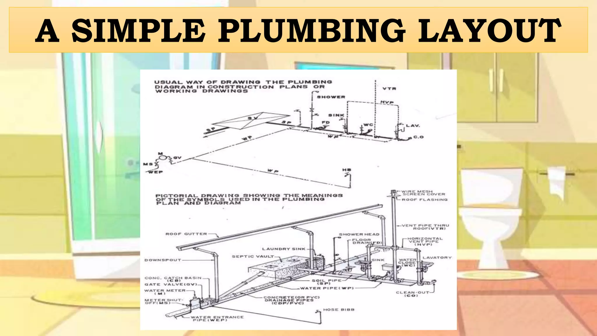
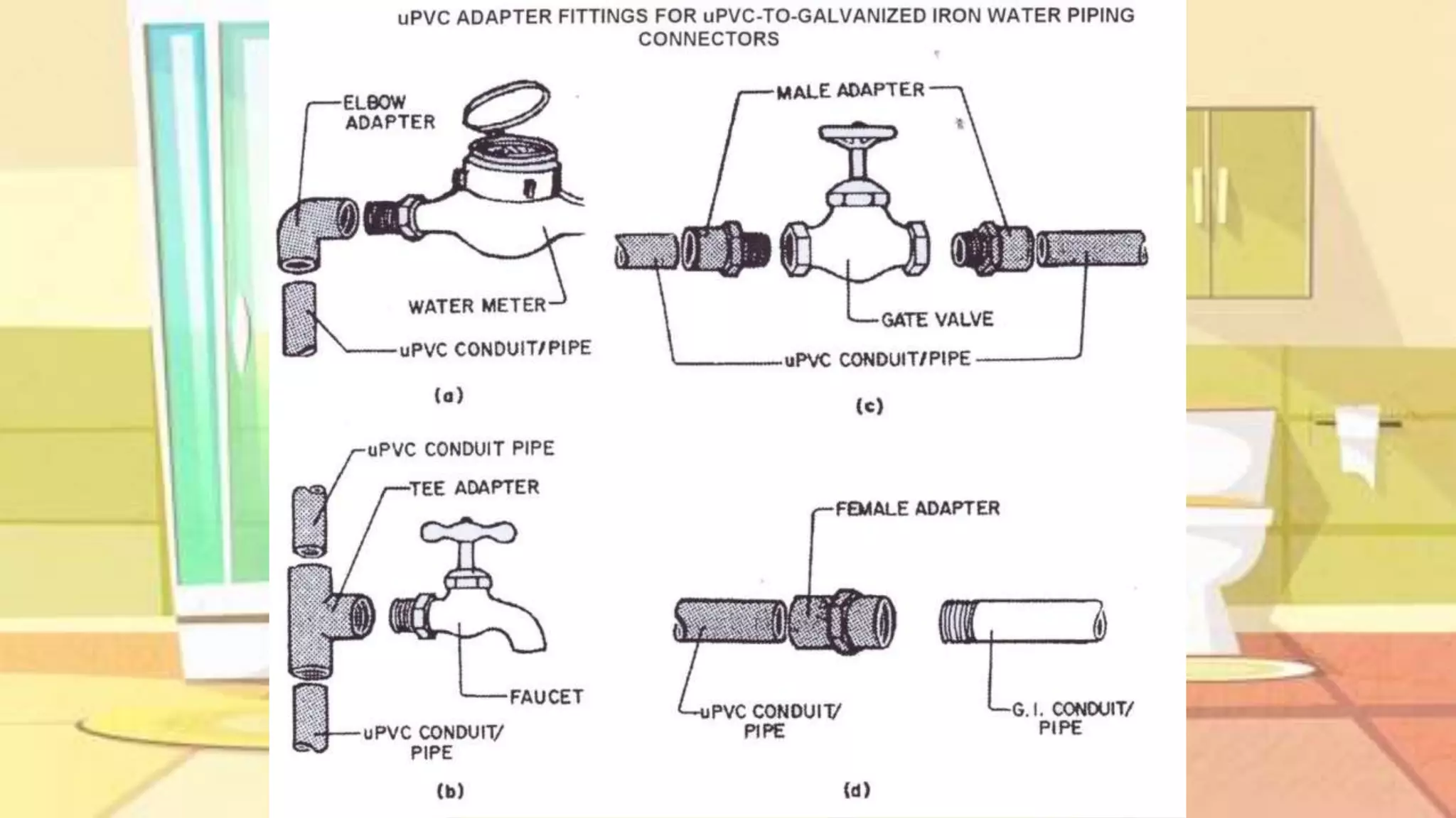
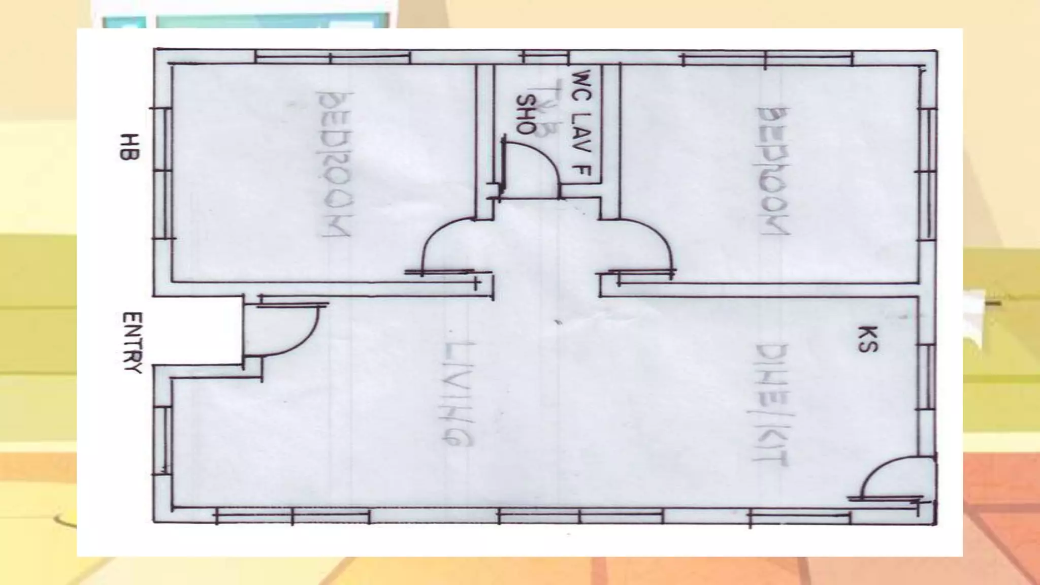
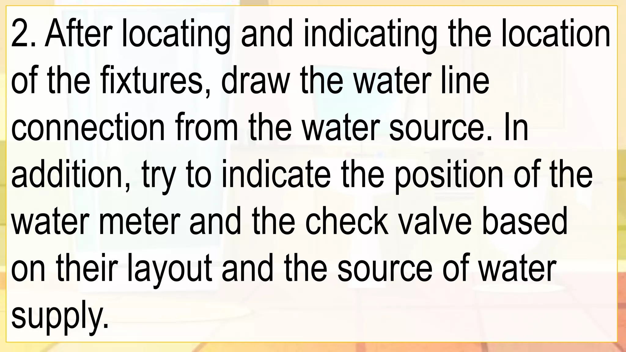
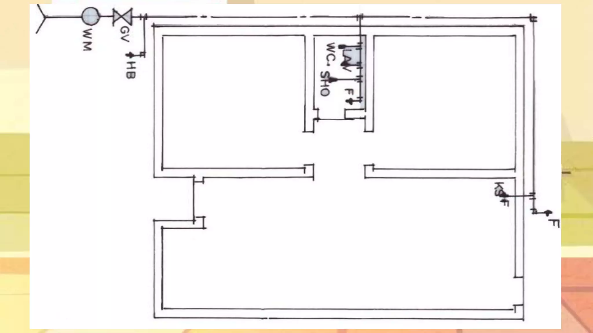
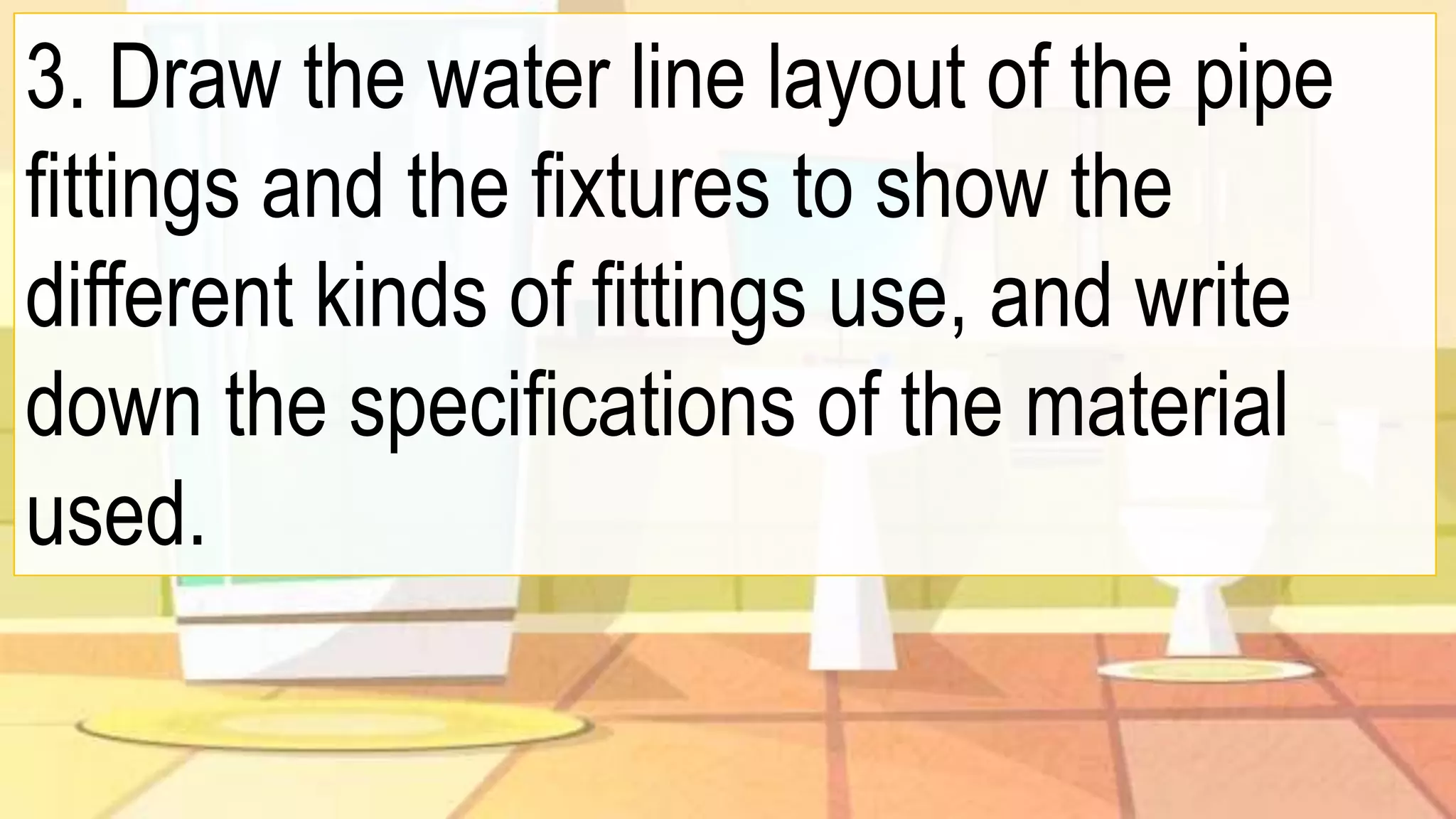
- Procedures for laying out a plumbing system in a floor plan include indicating fixture locations, drawing water line connections from the source, detailing pipe fittings and fixtures, specifying materials, and adding a legend.


![324493113-Draft-Water-Distribution-Systems [Autosaved].pptx](https://cdn.slidesharecdn.com/ss_thumbnails/324493113-draft-water-distribution-systemsautosaved-250301130223-db0de8d5-thumbnail.jpg?width=640&height=640&fit=bounds)


