This document summarizes the identification and modeling of structural dynamics characteristics of a water jet cutting machine. An iterative approach was used including theoretical modeling, simulation, experimental investigation, and model updating to develop an accurate dynamics model of the machine. A complex dynamic behavior was found. The developed model showed high correlation with experimental modal analysis, indicating it can be used with confidence to study the total system behavior.
In cylinder cold flow cfd simulation of ic engine using hybrid approacheSAT Publishing House
IJRET : International Journal of Research in Engineering and Technology is an international peer reviewed, online journal published by eSAT Publishing House for the enhancement of research in various disciplines of Engineering and Technology. The aim and scope of the journal is to provide an academic medium and an important reference for the advancement and dissemination of research results that support high-level learning, teaching and research in the fields of Engineering and Technology. We bring together Scientists, Academician, Field Engineers, Scholars and Students of related fields of Engineering and Technology
The paper presents the operating principle and the constructive solution of a rotating machine with two profiled rotors. The influence of the rotating piston height on the driving power of the machine is revealed.
Cfd Studies of Two Stroke Petrol Engine ScavengingIJERA Editor
This project deals with the numerical analysis of 2 stroke engine scavenging in two cases. One with an existing condition (Flat headed pistons) and another with a new design (Dome headed piston) .The numerical analysis is done with help of CFD software ANSYS FLUENT 14.5. Here, the modeling of engine piston with flat headed type and with dome headed types was done in workbench. In ANSYS FLUENT after the geometrical design, for the dynamic motion meshing is used and set up species transport model also. At first the scavenging effect of flat headed piston is analyzed. Later the simulation of piston with dome headed type was also checked. Analyzing the variations from each and selected the best method for scavenging. Finally the scavenging efficiency is calculated for both type arrangements.
Design procedure of an electrohydraulic driveeSAT Journals
Abstract Aerodynamicists use wind tunnel to test models as well as for proposed aircraft components and engines. In order to keep these models fixed in place for testing, ground based equipment is essential. Electrohydraulic drives form the back bone of such type of mechanism which requires continuous motion for life time operations with controlled motion for start stop and bi-directional motion mechanisms. Focus of this paper is on systematic approach for optimal designing of a typical electrohydraulic drive that will provide roll motion to the testing model with emphasis on reliability of the system. This paper further highlights the design, selection, testing and qualification procedures of different elements of the drive and the electrohydraulic drive assembly as a whole. Keywords - Design, Develop, Electrohydraulic roll drive, Spindle.
An Optimization of pallet weight is an key point to be considered for lean manufacturing,cost reduction & effective operations. An effort for optimization of pallets has been carried out by many researchers using various methods considering static& dynamic loading conditions.
Design Optimization and Analysis of a Steam Turbine Rotor GroovesIOSR Journals
A large variety of turbo-machinery rotor groove geometries are used in industry. However, there is
no specific attempt made to compare them on the basis of performance. This paper provides an attempt to fill
that gap aiming to find an optimum geometry. The main objective of the investigations is to reduce fillet stress
concentration factor and associated deformations. The present work carries out the design modification of fillet
of a Steam Turbine Rotor. Finite Element Analysis is performed using ANSYS Workbench that is used to
determine the fillet stresses effectively to modify the blade rotor grooves. The low pressure steam turbine rotor
blades have usually a history of stress failure. They suffer from tensile and bending stresses partly due to the
centrifugal force as a result of high rotational speeds and partly due to high pressure, temperature and speed
steam loading. The centrifugal force is one of the problems that face the designers of turbine blades especially
the long ones. The designer always aims at reducing these stresses. One way to do so is by the reduction of
stress concentration factor which takes place between the rotor and its groove. That is to make the rotor blade
of variable cross section instead of straight. This paper presents the method of reducing stress concentration
factor as well as reduction in the deformation of the rotor
DESIGN AND OPTIMIZATION OF CRITICAL PART OF A ROTARY TABLE USED IN HORIZONTAL...IAEME Publication
Growing industry demands low manufacturing cost, saving of material, low cost material, ease of transportation etc. This demand leads to use different type of material and various techniques to increase productivity.
Design and analysis of drive shaft for heavy duty truckeSAT Journals
Abstract
Drive shafts in commercial heavy duty vehicle are subjected to cyclic loads due to variation in the torque demanded by the
varying road loads. Cases of failure of the drive shaft of heavy duty trucks have been reported, which provides an opportunity to
investigate the issue.
In this project an attempt has been made on prediction of fatigue life of the drive shaft using FEA technique. The load spectrum
acting on the drive shaft is calculated for specified terrain. Structural analysis was carried out on the FE model of drive shaft, and
potential areas of high stress concentration are obtained. Von Mises stress, fatigue damage, fatigue life, factor of safety and total
deformation are the results of fatigue analysis.
It was observed that from the static analysis that the roots of the splines are the areas of high stress concentration. The fatigue
analysis revels that the drive shaft fails in the region of high stress concentration as expected. The fatigue life of the component is
found to be infinite for design pay load. The life of the drive shaft for 40% and 50% over load is 69806 kilometers and 20564
kilometers respectively. The present work can be used in automobile industry as a reference for predicting life of any component,
in the drive line of the automobile subjected to non constant amplitude loading.
Keywords: Fatigue, Cumulative Damage, Stress-life, Duty cycle, Numerical Fatigue Analysis, Palmgren-Miner Linear
damage rule, Rain-flow cycle counting.
finite element analysis & design optimization of material handling equipmentINFOGAIN PUBLICATION
Material handling equipment is mechanical equipment used for the movement, storage, control products throughout the process of manufacturing, and disposal. The different types of material handling equipment can be classified into four major categories, transport equipment, positioning equipment, unit load formation equipment, and storage equipment. Excavator is used to excavate the material of the ground on which the machine rests and load it into trucks or tractor. In the severe working conditions, excavator parts are subjected to very high loads. The excavator mechanism must work reliably under random working conditions. Thus it is very much essential for the designers to evaluate not only a equipment of maximum reliability but also of minimum weight and cost, considering design safe under all loading conditions. It can be accomplished that, mechanical strength analysis is an important to step in the design of excavator parts. Finite Element Analysis (FEA) is the most appropriate technique in strength calculations of the structures working under known load and boundary conditions. In general, computer aided drawing model of the parts to be analyzed must to be set prior to the FEA. It is also promising to reduce the weight of the mechanism by performing optimization in FEA. This paper provides the platform for proceeding for the Modeling, FEA and optimization of backhoe excavator attachment, which was already carried out by other researchers for their related applications and it can be very helpful for development of any material handling equipment and new excavator attachment.
Connecting Rods are practically generally used in all varieties of automobile engines. Acting as an
intermediate link between the piston and the crankshaft of an engine. It is responsible for transmission of the up
and down motion of the piston to the crankshaft of the engine, by converting the reciprocating motion of the
piston to the rotary motion of crankshaft. Thus, this study aims to carry out for the load, strain and stress analysis
of the crank end of the connecting rod of different materials. Based on which the High Strength Carbon Fiber
connecting rod will be compared with connecting rod made up of Stainless Steel and Aluminum Alloy. The
results can be used for optimization for weight reduction and for design modification of the connecting rod. Pro-E
software is used for modeling and analyses are carried out in ANSYS software. The results archived can also help
us identify the spot or section where chances of failure are high due to stress induced. Also the results obtained
can be used to modify the existing designs so that better performance and longer life cycle can be archived.
Keywords —Connecting Rod, Pro-E, FEA, ANSYS Workbench, Crank, Crankshaft, Piston, Carbon Fiber,
Stainless Steel, Aluminum Alloy.
This paper considers issues related to increasing energy efficiency in electric drives of pilger rolling mills, presenting kinematics of such mills, provides justification for the general load chart, presents the detailed review of reference materials on technical energy saving solutions, and suggests a math model of an electric drive with a field regulated reluctance machine. The paper suggests key methods of saving energy in electric drives of pilger mills, namely: kinematic scheme improvement; main energy drainers and ways of energy loss reduction in electric drives with direct- and alternate-current motors, energy-saving electric drive control profiles. The article compares energy-saving resources in electric drives with various-type motors (direct-current motors, synchronous motors, and field regulated reluctance machine), clarifies the scheme of energy-saving resource implementation, provides the qualitative evaluation of electric drive control method efficiency. The accent is made on high energy efficiency of the proportionate control of armature and excitation circuits and across the range of torque in electric drives of abruptly-variable-load mills. The highest economic effect is reached in the electric drive with a field regulated reluctance machine – by means of implementing the energy-efficient electromechanical converter and applying energy-saving control profiles.
The need for high pump performance and efficiency continue to encourage the study of flow between two parallel co-rotating discs in multiple discs pump or turbine. Therefore, this study entails the design, construction and CFD simulation of a 3D Tesla pump model axisymmetric swirling flow in order to enhance the understanding of Tesla pump for future development.
Method of solution entails designing and construction of a small prototype tesla pump and then using the design geometry and parameters to design and perform numerical simulation. The results of the numerical simulation were then analyzed.
The result obtained indicates static pressure to have minimum value of -4.7791Pa at the outlet and 13.777Pa at the pump inlet and with velocity magnitude having minimum velocity of 0.00m/s and maximum velocity of 4.12m/s. The strength of the velocity was seen to be very high at the pump outlet. The analysis radial velocity showed minimum value of -0.508m/s and maximum value of 3.981m/s with the radial velocity vector being concentrated at the discs periphery and outlet.
Model simulation results exhibited smooth pressure and velocity profiles. With the 3D simulation all flow variables are able to be predicted.
Karakuri based dolly frames unstacking systemAnshumanRaj8
The project aims to design a Karakuri Kaizen model to stack and unstack dolly frames efficiently and ergonimically. The design havve been proposed and assembled using standard components from Minitec using Solidworks version 2020. The required inclination angle for the conveyor and the deadwight of the protoype is calculated for the designed assembly. Frame count validation electronic unit is designed to check if the frames per minutes worked in a given set of time is maintained. The electronic unit designed in Kicad , required electronic components and 3d printed, housing for the electronicunit is designed and assembled.
Optimization of Closure Law of Guide Vanes for an Operational Hydropower Plan...Dr. Amarjeet Singh
This paper addresses the optimization of twostage closure law of guide vanes in an operational
hydropower plant of Nepal. The mathematical model
has been established in commercial software Bentley
Hammer, whose correctness has been validated by
comparing the results with the data of experimental
load rejection test. The validated mathematical model
has been employed to find the parameters of optimum
closure pattern, which minimizes the non-linear
objective function of maximum water pressure and
maximum rotational speed of turbine.
Traditional vs Integrated Electric Rod Style Actuatorsdietrich42
White paper discussing advantages and disadvantages of rod style pneumatic cylinders , electric actuators and integrated electric actuators in motion control applications.
Design and Analysis Nose Landing Gear SupportIJSRD
Nose landing gear support bracket is one of the main parts in the nose landing gear assembly, whose function is to maintain the stability of the landing gear during the movements. This work is focused on the FEA analysis of support bracket by varying the stress concentration area, The objective of this work is to determine the static and modal analysis of support bracket with different stress concentration areas, then analysis is done using ANSYS WORKBENCH, These results could provide some useful suggestions for design and improvement for the better component
Estimation of water momentum and propeller velocity in bow thruster model of...IJECEIAES
Autonomous surface vehicle (ASV) is a vehicle in the form of an unmanned on-water surface vessel that can move automatically. As such, an automatic control system is essentially required. The bow thruster system functions as a propulsion control device in its operations. In this research, the water momentum and propeller velocity were estimated based on the dynamic bow thruster model. The estimation methods used is the Kalman filter (KF) and ensemble Kalman filter (EnKF). There are two scenarios: tunnel thruster condition and open-bladed thruster condition. The estimation results in the tunnel thruster condition showed that the root mean square error (RMSE) by the EnKF method was relatively smaller, that is, 0.7920 and 0.1352, while the estimation results in the open-bladed thruster condition showed that the RMSE by the KF method was relatively smaller, that is, 1.9957 and 2.0609.
Dr. Sean Tan, Head of Data Science, Changi Airport Group
Discover how Changi Airport Group (CAG) leverages graph technologies and generative AI to revolutionize their search capabilities. This session delves into the unique search needs of CAG’s diverse passengers and customers, showcasing how graph data structures enhance the accuracy and relevance of AI-generated search results, mitigating the risk of “hallucinations” and improving the overall customer journey.
DevOps and Testing slides at DASA ConnectKari Kakkonen
My and Rik Marselis slides at 30.5.2024 DASA Connect conference. We discuss about what is testing, then what is agile testing and finally what is Testing in DevOps. Finally we had lovely workshop with the participants trying to find out different ways to think about quality and testing in different parts of the DevOps infinity loop.
Removing Uninteresting Bytes in Software FuzzingAftab Hussain
Imagine a world where software fuzzing, the process of mutating bytes in test seeds to uncover hidden and erroneous program behaviors, becomes faster and more effective. A lot depends on the initial seeds, which can significantly dictate the trajectory of a fuzzing campaign, particularly in terms of how long it takes to uncover interesting behaviour in your code. We introduce DIAR, a technique designed to speedup fuzzing campaigns by pinpointing and eliminating those uninteresting bytes in the seeds. Picture this: instead of wasting valuable resources on meaningless mutations in large, bloated seeds, DIAR removes the unnecessary bytes, streamlining the entire process.
In this work, we equipped AFL, a popular fuzzer, with DIAR and examined two critical Linux libraries -- Libxml's xmllint, a tool for parsing xml documents, and Binutil's readelf, an essential debugging and security analysis command-line tool used to display detailed information about ELF (Executable and Linkable Format). Our preliminary results show that AFL+DIAR does not only discover new paths more quickly but also achieves higher coverage overall. This work thus showcases how starting with lean and optimized seeds can lead to faster, more comprehensive fuzzing campaigns -- and DIAR helps you find such seeds.
- These are slides of the talk given at IEEE International Conference on Software Testing Verification and Validation Workshop, ICSTW 2022.
GraphSummit Singapore | The Future of Agility: Supercharging Digital Transfor...Neo4j
Leonard Jayamohan, Partner & Generative AI Lead, Deloitte
This keynote will reveal how Deloitte leverages Neo4j’s graph power for groundbreaking digital twin solutions, achieving a staggering 100x performance boost. Discover the essential role knowledge graphs play in successful generative AI implementations. Plus, get an exclusive look at an innovative Neo4j + Generative AI solution Deloitte is developing in-house.
Smart TV Buyer Insights Survey 2024 by 91mobiles.pdf91mobiles
91mobiles recently conducted a Smart TV Buyer Insights Survey in which we asked over 3,000 respondents about the TV they own, aspects they look at on a new TV, and their TV buying preferences.
GraphSummit Singapore | The Art of the Possible with Graph - Q2 2024Neo4j
Neha Bajwa, Vice President of Product Marketing, Neo4j
Join us as we explore breakthrough innovations enabled by interconnected data and AI. Discover firsthand how organizations use relationships in data to uncover contextual insights and solve our most pressing challenges – from optimizing supply chains, detecting fraud, and improving customer experiences to accelerating drug discoveries.
Epistemic Interaction - tuning interfaces to provide information for AI supportAlan Dix
Paper presented at SYNERGY workshop at AVI 2024, Genoa, Italy. 3rd June 2024
https://alandix.com/academic/papers/synergy2024-epistemic/
As machine learning integrates deeper into human-computer interactions, the concept of epistemic interaction emerges, aiming to refine these interactions to enhance system adaptability. This approach encourages minor, intentional adjustments in user behaviour to enrich the data available for system learning. This paper introduces epistemic interaction within the context of human-system communication, illustrating how deliberate interaction design can improve system understanding and adaptation. Through concrete examples, we demonstrate the potential of epistemic interaction to significantly advance human-computer interaction by leveraging intuitive human communication strategies to inform system design and functionality, offering a novel pathway for enriching user-system engagements.
Why You Should Replace Windows 11 with Nitrux Linux 3.5.0 for enhanced perfor...SOFTTECHHUB
The choice of an operating system plays a pivotal role in shaping our computing experience. For decades, Microsoft's Windows has dominated the market, offering a familiar and widely adopted platform for personal and professional use. However, as technological advancements continue to push the boundaries of innovation, alternative operating systems have emerged, challenging the status quo and offering users a fresh perspective on computing.
One such alternative that has garnered significant attention and acclaim is Nitrux Linux 3.5.0, a sleek, powerful, and user-friendly Linux distribution that promises to redefine the way we interact with our devices. With its focus on performance, security, and customization, Nitrux Linux presents a compelling case for those seeking to break free from the constraints of proprietary software and embrace the freedom and flexibility of open-source computing.
GridMate - End to end testing is a critical piece to ensure quality and avoid...ThomasParaiso2
End to end testing is a critical piece to ensure quality and avoid regressions. In this session, we share our journey building an E2E testing pipeline for GridMate components (LWC and Aura) using Cypress, JSForce, FakerJS…
LF Energy Webinar: Electrical Grid Modelling and Simulation Through PowSyBl -...DanBrown980551
Do you want to learn how to model and simulate an electrical network from scratch in under an hour?
Then welcome to this PowSyBl workshop, hosted by Rte, the French Transmission System Operator (TSO)!
During the webinar, you will discover the PowSyBl ecosystem as well as handle and study an electrical network through an interactive Python notebook.
PowSyBl is an open source project hosted by LF Energy, which offers a comprehensive set of features for electrical grid modelling and simulation. Among other advanced features, PowSyBl provides:
- A fully editable and extendable library for grid component modelling;
- Visualization tools to display your network;
- Grid simulation tools, such as power flows, security analyses (with or without remedial actions) and sensitivity analyses;
The framework is mostly written in Java, with a Python binding so that Python developers can access PowSyBl functionalities as well.
What you will learn during the webinar:
- For beginners: discover PowSyBl's functionalities through a quick general presentation and the notebook, without needing any expert coding skills;
- For advanced developers: master the skills to efficiently apply PowSyBl functionalities to your real-world scenarios.
GDG Cloud Southlake #33: Boule & Rebala: Effective AppSec in SDLC using Deplo...James Anderson
Effective Application Security in Software Delivery lifecycle using Deployment Firewall and DBOM
The modern software delivery process (or the CI/CD process) includes many tools, distributed teams, open-source code, and cloud platforms. Constant focus on speed to release software to market, along with the traditional slow and manual security checks has caused gaps in continuous security as an important piece in the software supply chain. Today organizations feel more susceptible to external and internal cyber threats due to the vast attack surface in their applications supply chain and the lack of end-to-end governance and risk management.
The software team must secure its software delivery process to avoid vulnerability and security breaches. This needs to be achieved with existing tool chains and without extensive rework of the delivery processes. This talk will present strategies and techniques for providing visibility into the true risk of the existing vulnerabilities, preventing the introduction of security issues in the software, resolving vulnerabilities in production environments quickly, and capturing the deployment bill of materials (DBOM).
Speakers:
Bob Boule
Robert Boule is a technology enthusiast with PASSION for technology and making things work along with a knack for helping others understand how things work. He comes with around 20 years of solution engineering experience in application security, software continuous delivery, and SaaS platforms. He is known for his dynamic presentations in CI/CD and application security integrated in software delivery lifecycle.
Gopinath Rebala
Gopinath Rebala is the CTO of OpsMx, where he has overall responsibility for the machine learning and data processing architectures for Secure Software Delivery. Gopi also has a strong connection with our customers, leading design and architecture for strategic implementations. Gopi is a frequent speaker and well-known leader in continuous delivery and integrating security into software delivery.
Elevating Tactical DDD Patterns Through Object CalisthenicsDorra BARTAGUIZ
After immersing yourself in the blue book and its red counterpart, attending DDD-focused conferences, and applying tactical patterns, you're left with a crucial question: How do I ensure my design is effective? Tactical patterns within Domain-Driven Design (DDD) serve as guiding principles for creating clear and manageable domain models. However, achieving success with these patterns requires additional guidance. Interestingly, we've observed that a set of constraints initially designed for training purposes remarkably aligns with effective pattern implementation, offering a more ‘mechanical’ approach. Let's explore together how Object Calisthenics can elevate the design of your tactical DDD patterns, offering concrete help for those venturing into DDD for the first time!
A tale of scale & speed: How the US Navy is enabling software delivery from l...sonjaschweigert1
Rapid and secure feature delivery is a goal across every application team and every branch of the DoD. The Navy’s DevSecOps platform, Party Barge, has achieved:
- Reduction in onboarding time from 5 weeks to 1 day
- Improved developer experience and productivity through actionable findings and reduction of false positives
- Maintenance of superior security standards and inherent policy enforcement with Authorization to Operate (ATO)
Development teams can ship efficiently and ensure applications are cyber ready for Navy Authorizing Officials (AOs). In this webinar, Sigma Defense and Anchore will give attendees a look behind the scenes and demo secure pipeline automation and security artifacts that speed up application ATO and time to production.
We will cover:
- How to remove silos in DevSecOps
- How to build efficient development pipeline roles and component templates
- How to deliver security artifacts that matter for ATO’s (SBOMs, vulnerability reports, and policy evidence)
- How to streamline operations with automated policy checks on container images
Unlocking Productivity: Leveraging the Potential of Copilot in Microsoft 365, a presentation by Christoforos Vlachos, Senior Solutions Manager – Modern Workplace, Uni Systems
State of ICS and IoT Cyber Threat Landscape Report 2024 previewPrayukth K V
The IoT and OT threat landscape report has been prepared by the Threat Research Team at Sectrio using data from Sectrio, cyber threat intelligence farming facilities spread across over 85 cities around the world. In addition, Sectrio also runs AI-based advanced threat and payload engagement facilities that serve as sinks to attract and engage sophisticated threat actors, and newer malware including new variants and latent threats that are at an earlier stage of development.
The latest edition of the OT/ICS and IoT security Threat Landscape Report 2024 also covers:
State of global ICS asset and network exposure
Sectoral targets and attacks as well as the cost of ransom
Global APT activity, AI usage, actor and tactic profiles, and implications
Rise in volumes of AI-powered cyberattacks
Major cyber events in 2024
Malware and malicious payload trends
Cyberattack types and targets
Vulnerability exploit attempts on CVEs
Attacks on counties – USA
Expansion of bot farms – how, where, and why
In-depth analysis of the cyber threat landscape across North America, South America, Europe, APAC, and the Middle East
Why are attacks on smart factories rising?
Cyber risk predictions
Axis of attacks – Europe
Systemic attacks in the Middle East
Download the full report from here:
https://sectrio.com/resources/ot-threat-landscape-reports/sectrio-releases-ot-ics-and-iot-security-threat-landscape-report-2024/
Generative AI Deep Dive: Advancing from Proof of Concept to ProductionAggregage
Join Maher Hanafi, VP of Engineering at Betterworks, in this new session where he'll share a practical framework to transform Gen AI prototypes into impactful products! He'll delve into the complexities of data collection and management, model selection and optimization, and ensuring security, scalability, and responsible use.
FIDO Alliance Osaka Seminar: Passkeys at Amazon.pdf
Water Jet
1. Identification and Modelling of Structural Dynamics Characteristics of a
Water Jet Cutting Machine
Johan E Wall, Thomas L Englund, Ansel J Berghuvud
Department of Mechanical Engineering
Blekinge Institute of Technology
SE-371 79 Karlskrona, Sweden.
http://www.bth.se
ABSTRACT
Dynamic characteristics of a water jet cutting machine, to be used in a virtual machine implemented in an analysis
tool for engineering design, are derived. Machine users need for more cost effective production put demands on
faster cutting. Faster cutting results in higher dynamic loads. As a consequence, problems with unwanted
vibrations that decrease cutting precision may occur. Prediction of such potential problems is facilitated by an
analysis tool for evaluation of suggested design solutions early in the product development process. The present
work contributes to ongoing development of such an analysis tool for design engineers. An iterative approach
including both theoretical and experimental analysis is applied in order to derive a structural dynamics model of
the studied machine. A complex dynamic behaviour of the machine is found. High correlation between results
obtained from theoretical and experimental modal analysis implies that the developed model can be used with
confidence in future studies of the machine’s total system behaviour.
Keywords: Experimental investigation, Modal analysis, Modelling, Structural dynamics, Vibrations.
1. INTRODUCTION
Water jet cutting machine users desire higher productivity for better competitiveness. A way to achieve this is
faster cutting and better cutting precision. However, increased cutting speed gives higher dynamic loads on the
machine. Problems with unwanted vibrations that decrease cutting precision may follow. Machine developers
strive to both fulfil the increased customer demands and to decrease total development costs. This, and a
shortened time-to-market, is believed to be achievable by prediction of the machine behaviour earlier in the
product development process through theoretical modelling and simulation. The use of theoretical modelling and
simulation facilitates design optimisation and minimises the number of needed physical prototypes. In general,
enabling an early prediction of the system behaviour also facilitates integration of specialised disciplines in a
concurrent engineering process, as for example described by Andreasen [1] and Olsson [2]. An analysis tool for
appraisal of suggested design solutions is therefore desirable. This is of particular interest in the current case
since the produced machines often are unique as they are modified to suite particular customer needs.
Water jet cutting is an erosion process. A high velocity water jet is created by letting out water through a small
orifice from a pressurised vessel. Cutting with a jet of water purely is appropriate for soft materials. Abrasives are
added to the water jet for cutting of hard materials. More information about this technology is given by for example
Draughon [3], Öjmertz [4] and Water Jet Sweden AB [5].
The studied type of product is an example of a mechatronic system. Analysis considering the characteristics of
both the control system and the mechanical parts are therefore needed to enable optimisation towards the
desired behaviour of the machine.
2. The work presented here is a part of a co-operation project between the Department of Mechanical Engineering
at Blekinge Institute of Technology, Karlskrona, Sweden and Water Jet Sweden Inc., Ronneby, Sweden. The
overall long-term goal is to derive a virtual machine that can be used by design engineers to optimise accuracy
and cutting speed, predict durability, evaluate safety, etc., during the development of new machine designs. The
selected approach for studies of the mechatronic system behaviour includes a mixture of hardware and software
in the loop. This puts demands on simulation and interaction with hardware in real-time. Simulation models should
therefore be as computationally efficient as possible while still being accurate enough for the characteristics they
are supposed to describe. The development of the virtual machine is further described by Bathelt and Jönsson
[6].
The present work focuses on the mechanical parts of a typical water jet cutting machine from Water Jet Sweden
Inc. An iterative approach including theoretical modelling, simulation, experimental investigation and model
updating is applied in order to gain understanding of the dynamic behaviour of the system and to develop a
structural dynamics model of the studied machine, see figure 1.
Figure 1. An overview of the iterative approach applied.
2. DESIGN OF THE MACHINE
Knowledge and understanding about the general design of the studied machine is needed for both the theoretical
modelling and experimental investigation. The focus is put on the mechanical parts that are considered to
influence cutting precision.
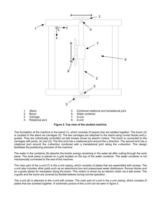
A schematic picture of the machine can be seen in figure 2. The main parts are indicated in the figure. The
machine has two axles of motion in the horizontal plane and a working area of about three by three metres.
3. 1. Stand. 5. Combined rotational and translational joint.
2. Boom. 6. Water container.
3. Carriage. 7. X-unit.
4. Rotational joint. 8. Z-unit.
Figure 2. Top view of the studied machine.
The foundation of the machine is the stand (1), which consists of beams that are welded together. The boom (2)
is coupled to the stand via carriages (3). The two carriages are attached to the stand using runner blocks and y-
guides. They are individually controlled via ball screws driven by electric motors. The boom is connected to the
carriages with joints, (4) and (5). The first end has a rotational joint around the z-direction. The second end has a
rotational joint around the z-direction combined with a translational joint along the x-direction. This design
facilitates the positioning precision of the machine.
The water in the container (6) absorbs the kinetic energy remaining in the water jet after cutting through the work
piece. The work piece is placed on a grid located on the top of the water container. The water container is not
mechanically connected to the rest of the machine.
The main part of the x-unit (7) is the x-unit casing, which consists of plates that are assembled with screws. The
x-unit also includes other parts such as an electronics box and pressurised water distributors. Runner blocks and
an x-guide allows for translation along the boom. This motion is driven by an electric motor via a ball screw. The
x-guide and the boom are covered by flexible bellows during normal operation.
The z-unit (8) is attached to the x-unit with screws. The main part of z-unit is the z-unit casing, which consists of
plates that are screwed together. A schematic picture of the z-unit can be seen in figure 3.
4. 9. Cutting head carrier beam. 14. Bellows.
10. Z-unit casings, containing racks, 15. Abrasive medium dispensing apparatuses.
z-guides and runner blocks. 16. Dispensing apparatus carrier beam.
11. Electric motor, z-direction. 17. Boom.
12. Cutting heads. 18. X-unit.
13. Acceleration pipes.
Figure 3. Front view of the studied machine.
The z-guides, attached to the cutting head carrier beam (9), allow for motion in the z-direction via runner blocks,
located inside the z-unit casings (10). This makes it possible to adjust the distance between the cutting heads and
the work piece. The motion of the z-guides is driven by an electric motor (11) via racks and pinions.
The cutting heads (12), attached to the cutting head carrier beam, direct the water jets against the work piece.
The height of each cutting head can be individually adjusted by changing the mounting position on its acceleration
pipe (13)
The parts of the z-guides that are located between the z-unit casings and the cutting head carrier beam are
covered by flexible bellows (14). Abrasive medium dispensing apparatuses (15), from here on called dispensing
apparatuses, are placed at the top of the z-unit. These are attached to the z-unit via a carrier beam (16).
3. MODELLING
A theoretical model of the studied system is developed using the commercial finite element software I-deas (EDS
PLM Solutions [7]). Two models are developed, an initial model with high abstraction level is built before the
experimental investigations are carried out to give a rough understanding of the machine dynamics and to be
used for pre-test decisions (see chapter 4). The knowledge gained during the experimental investigation is used
to build a more realistic model of the machine, incorporating more parts and using a more detailed description of
the physical relationships between the included parts. This model is updated to correlate better with experimental
results. The final model is described below.
5. A straightforward modelling procedure to be suited for analysis early in the product development process is
strived for. The aim is to find a procedure that is suited for computationally efficient simulations in future studies of
this type of machine. Further, the focus is on vibration characteristics and not on detailed stress analysis. Beam
elements, lumped mass and mass moment of inertia elements, springs and rigid elements are therefore used. A
graphical representation of the developed model can be seen in figure 4.
CP CP CP
CP CP CP
CP
CP
CP
CP
CP
CP
Figure 4. Graphical representation of the finite element model.
The boom, the z-guides, the cutting head carrier beam, the dispensing apparatus carrier beam and the z-unit
casings are all long and slender structures and are therefore modelled using beam elements.
All internal parts in the z-unit casings, such as for example racks and runner blocks, are modelled using lumped
mass elements as they are assumed to be rigid. The dispensing apparatuses are modelled using lumped mass
and mass moment of inertia elements. These elements are coupled to the dispensing apparatus carrier beam
using rigid elements and rotational springs. The spring elements allow rotation around the x-direction and
accounts for the flexibility of the brackets holding the dispensing apparatuses. The spring coefficient is determined
experimentally. The cutting heads, except for the acceleration pipes, and their mountings on the cutting head
carrier beam are modelled using lumped mass and mass moment of inertia elements. The acceleration pipes are
modelled using beam elements. The studied system includes four dispensing apparatuses and eight cutting
heads.
The x-unit casing is modelled using beam elements although its flexibility is not considered to influence the
results. Beam elements are used because it is an easy way to get a correct mass and mass moment of inertia
distribution. Parts attached to the x-unit, such as the electronics box and the pressurised water distributors, are
accounted for by lumped mass elements. The stiffness of the connections between the x-unit and the boom
(bolted joints and couplings between runner blocks and x-guide) and the coupling between the runner blocks and
the z-guides are both modelled using rotational springs.
The stiffnesses of these springs are adjusted when updating the model since these are considered to be the most
uncertain parameters in the model. The springs are only allowed to rotate around the x-direction. Transducers
used during the experimental investigation are accounted for by lumped mass elements. In total, the finite
element model consists of 399 elements and 386 nodes.
The boundary conditions for the boom are applied to comply with its joints described in chapter 2, with the
exception of the y-direction where springs are inserted to account for the flexibility in the remaining parts not
included in the model (for example bending stiffness of carriages and axial stiffness of ball screws). The Lanczos
solver is used to solve for the natural frequencies and corresponding mode shapes of the derived model.
6. 4. EXPERIMENTAL INVESTIGATIONS
An experimental modal analysis is performed in order to investigate the dynamic characteristics of the studied
machine. The objectives are increased knowledge of the dynamic behaviour of the system and to obtain
reference data for updating of the theoretical model.
The experimental set-up is shown in figure 5. The actual boundary conditions present during normal operation of
the machine are used during all measurements.
Figure 5. The experimental set-up.
The machine is excited with a shaker via a force transducer and a stinger. To avoid possible leakage problems a
burst random force signal is used. The excitation point is chosen consulting the initial finite element model of the
machine. The strategy, described by Ahlin and Brandt [8], is to select the excitation point that best excites the
least significant mode. The excitation point is chosen on the cutting head carrier beam, see figure 5.
The responses are measured using piezoelectric accelerometers. The number and locations of measurement
points are chosen on basis of an AutoMAC calculated using the initial finite element model. The Modal Assurance
Criterion (MAC) is a tool to numerically quantify the degree of conformance between two sets of mode shapes. A
value of one indicates perfect correlation while a value of zero indicates no correlation. Using the AutoMAC the
mode shapes are correlated against themselves. The criterion used when deciding on suitable measurement
points is that the off-diagonal terms of the AutoMAC should be as low as possible to get a good separation of the
modes. In total 48 evenly distributed measurement points are chosen.
A Hewlett Packard VXI measuring system is used to acquire the experimental data and I-DEAS Test [9] is used
as a signal analyser to obtain Frequency Response Functions (FRFs). Due to hardware limitations only 7 out of
the 48 measurement points is covered in one measurement round while triaxial accelerometers are used. Since
different mass loading of the structure may cause serious problems when extracting the modal parameters (Maia
et al. [10], [8]), dummy masses are used.
No significant modes are present above 100 Hz, see figure 6. The frequency range of interest is therefore set to
be between 0 and 100 Hz. In this frequency interval the coherence is generally good except at some anti-
resonances.
7. −2
10
Velocity / Reaction force (m/Ns)
−3
10
−4
10
20 40 60 80 100 120 140 160 180 200
Frequency (Hz)
Figure 6. A typical FRF for the studied machine.
The quality of the experimental set-up is further investigated by checking the driving point FRF for consistency
and by performing a linearity check. FRFs are independent of the excitation level for linear structures. However,
this is not the case for non-linear structures. Three measurements with successively doubled excitation force are
performed and the measured FRFs are overlaid to investigate the linearity assumption. The difference in the
responses shown in figure 7 indicates that the dynamic behaviour of the studied machine is slightly non-linear.
However a linear approximation is considered appropriate for the present study.
Velocity / Reaction force (m/Ns)
−2
10
−3
10
10 20 30 40 50 60 70 80 90 100
Frequency (Hz)
Figure 7. FRFs overlaid for low (solid line), medium (dash-dot line) and high (dashed) excitation force.
8. The measured FRFs are exported to MATLAB [11] where the modal parameter extraction is performed using the
ModalTools Toolbox [12] developed by Saven EduTech AB. To obtain parameters of good quality only a part of
the complete frequency range of interest is analysed at a time. Measurement data of low signal-to-noise ratio are
not included in the modal parameter extraction to further improve the quality of the parameters.
5. RESULTS AND DISCUSSION
MAC values, natural frequencies and visual examination of mode shapes are used for comparison of the
theoretical and experimental results.
A MAC-matrix is calculated for appraisal of the correlation between identified experimental modes and their
theoretical counterparts, see figure 8.
Figure 8. The MAC-matrix showing correlation between theoretical and experimental mode shapes.
It is found very difficult to obtain good correlation between experimental and theoretical results considering the
cutting heads and dispensing apparatuses. These local responses are also found large in comparison with the
rest of the machine. The MAC-matrix is therefore very dependent on these responses if they are included. Due to
the above reasons they are not taken into account when calculating the MAC-matrix for appraisal of the global
response correlation of the machine.
As a consequence, some of the off-diagonal terms become rather large, which can be seen in figure 8. The
reason for this is that responses of the cutting heads and the dispensing apparatuses are important to separate
the mode shapes from each other. The diagonal MAC-values are however between 0.78 and 0.92 for the selected
modes, which indicates good correlation considering global responses.
A comparison between theoretical and experimental natural frequencies is shown in figure 9. The diagonal line
represents perfect matching. The crosses indicate the frequency match for each correlated mode pair.
9. 90
Theoretcial natural frequency (Hz)
80
70
60
50
40
30
20
10
0
0 20 40 60 80
Experimental natural frequency (Hz)
Figure 9. Comparison of theoretical and experimental natural frequencies.
The maximum difference in corresponding natural frequencies is below 10 per cent except for one mode. The
small and randomly distributed scatter is normal for this type of modelling and measurement process (Ewins [13]).
The results are summarised in table 1.
Table 1. Results.
Experimental Theoretical
Mode Correlationa (%) MAC
Frequency (Hz) Damping (%) Frequency (Hz)
1 15.6 2.85 15.7 0.36 0.88
2 19.5 1.14 21.3 9.42 0.92
3 28.4 0.86 30.9 8.68 0.91
4 - - 39.8 - -
5 54.4 0.63 48.8 -10.3 0.90
6 66.2 1.53 64.3 -2.87 0.78
7 - - 72.2 - -
8 84.1 1.00 83.2 -1.05 0.92
a
The correlations are calculated before rounding off.
The damping values are given as the fraction of critical damping and the correlation values are the relative
differences between experimental and theoretical natural frequencies.
Mode four and seven predicted by the theoretical model are not found experimentally. The reason for this is
believed to be that the main movement of these modes are in the x- and/or z-direction(s) while the machine is
only excited in y-direction during the experimental investigations.
Except for the modes presented above several modes associated with large local responses of the cutting heads
and dispensing apparatuses are seen both during the experimental and theoretical modal analysis in the
frequency interval between 20 and 50 Hz.
10. 6. CONCLUSIONS
The dynamic characteristics of a water jet cutting machine are investigated in this work. An iterative approach
combining theoretical and experimental analysis is used in order to develop a structural dynamics model of the
machine. Due to the complex dynamic characteristics of the machine it is very difficult to create a model that
reflects reality without performing experimental investigations, which are often a complex task in its own. It is
therefore believed that the iterative approach used in this work is efficient when analysing this kind of systems.
The good correlation between experimental and theoretical results implies that the developed model can be used
with confidence as a basis for further work on creating a reliable model to be used in an analysis tool for
predicting the dynamic characteristics of new designs.
The final aimed for application of the theoretical model built in this work is to be used in real-time simulations of
the virtual machine. To be suited for this the model must be computationally inexpensive. The presented model
therefore consists of computationally effective finite elements, such as beam elements and lumped mass
elements. The good correlation implies that the level of detail in the model is sufficient to describe the complex
dynamic characteristics of the machine. However, further simplifications should be investigated and strived for in
the future.
To enable experimental identification of modes also in the x- and z-directions a different excitation direction and
possibly also multiple shaker excitation should be considered.
Actual mechanical properties of couplings between machine parts are identified as both difficult and necessary to
consider in the modelling. On basis of the performed linearity check the studied machine is considered as linear in
the present study. The validity of this assumption should however be more thoroughly investigated in future
studies.
7. ACKNOWLEDGEMENTS
The financial support from the Swedish Foundation for Knowledge and Competence Development and Water Jet
Sweden Inc. making this project possible is gratefully acknowledged.
REFERENCES
1. Andreasen, M. & Hein, L., Integrated product development, Springer Verlag, 1987.
2. Olsson, F., Systematic design, Doctoral Thesis, Department of Machine Design, Lund Institute of
Technology, Sweden, 1976. (In Swedish)
3. Draughon, R.N., Overview of waterjet applications in manufacturing, Proceedings of the First U.S. Water
Jet Conference, 1981.
4. Öjmertz, C., Abrasive waterjet machining, Licentiate Thesis, Department of Production Engineering,
Chalmers University of Technology, Sweden, 1994.
5. Water Jet Sweden AB, http://www.waterjet.se. (2003-10-06)
6. Bathelt, J. & Jönsson, A., How to implement the virtual machine concept using xPC target, Proceedings
of the The Nordic MATLAB Conference, Copenhagen, Denmark, 2003.
7. I-deas, EDS PLM Solutions, http://www.eds.com.
8. Ahlin, K. & Brandt, A., Experimental modal analysis in practice, Saven EduTech AB, Sweden, 2001.
9. I-DEAS Test, MTS Systems Corporation, http://www.mts.com.
10. Maia, N.M.M. & Silva, J.M.M. (eds.), Theoretical and experimental modal analysis, Research Studies
Press, UK, 1997.
11. MATLAB, The MathWorks Inc., http://www.mathworks.com.
12. Modal Tools, Saven EduTech AB, http://www.vibratools.com.
13. Ewins, D.J., Modal testing: theory, practice and application, Research Studies Press, UK, 2000.