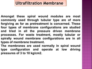
Downloaded 172 times
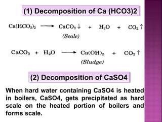
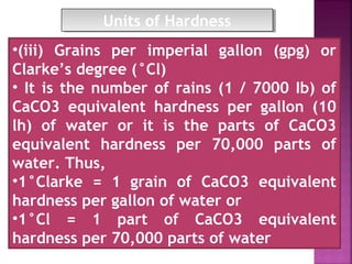
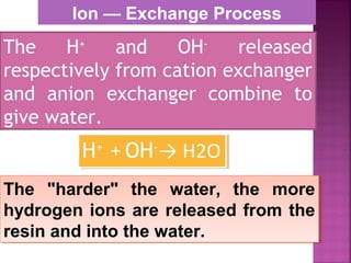
![Treatment with sodium aluminate (NaAlO2)
When boiler water is treated with NaAIO2 in
solution, it gets hydrolysed to yield NaOH and
Al(OH)3
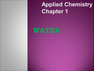
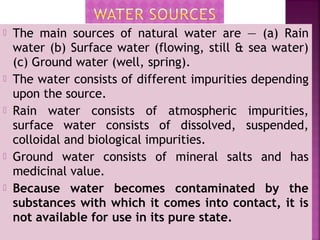
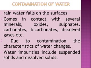
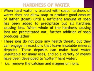
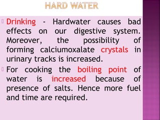
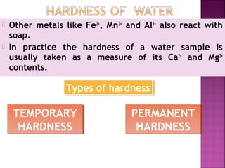
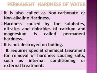
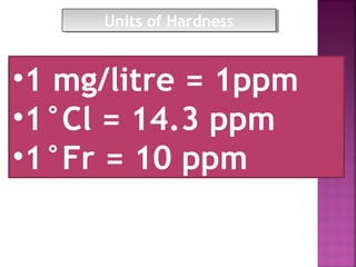
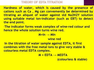
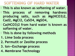
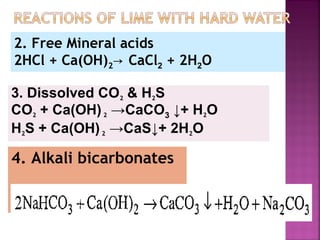
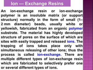
Treatment with sodium aluminate (NaAlO2)
When boiler water is treated with NaAIO2 in
solution, it gets hydrolysed to yield NaOH and
Al(OH)3
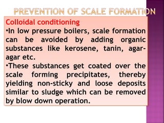
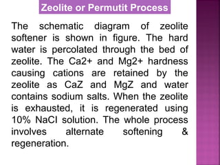
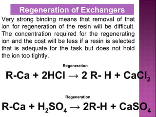
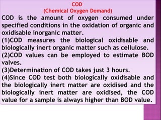
Calgon conditioning
Sodium hexametaphosphate Na2[Na4(PO3)6] is added
to boiler water. It prevents the scale formation by
forming soluble complex compound.
Calgon conditioning
Sodium hexametaphosphate Na2[Na4(PO3)6] is added
to boiler water. It prevents the scale formation by
forming soluble complex compound.
(Gelatinous precipitate](https://image.slidesharecdn.com/waternew-160407165301/85/Water-35-320.jpg)
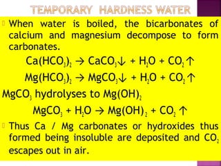
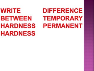
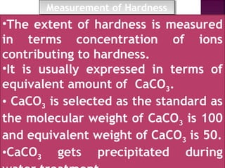
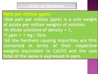
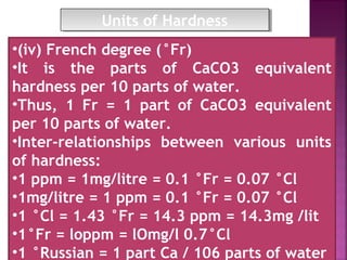
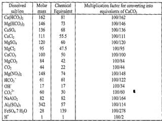
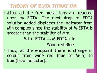
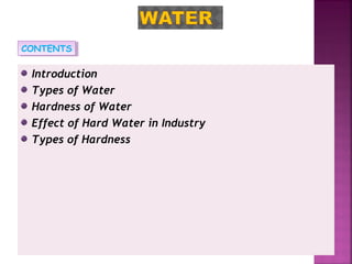
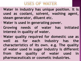
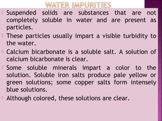
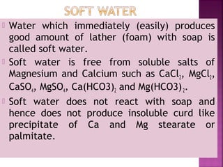
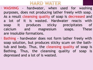
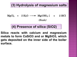
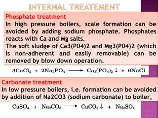
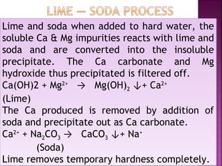
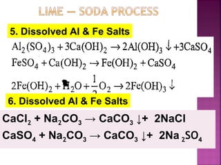
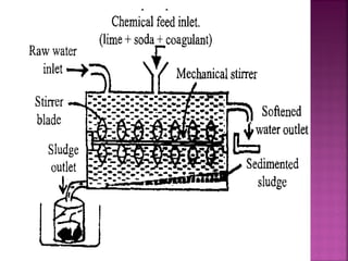
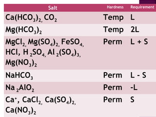
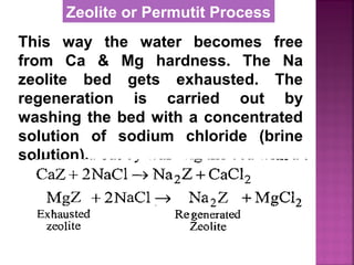
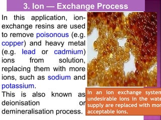
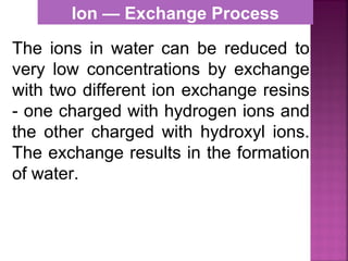
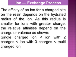
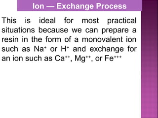
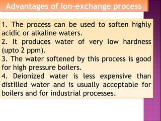
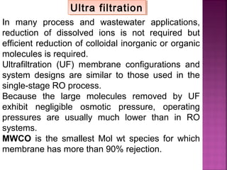
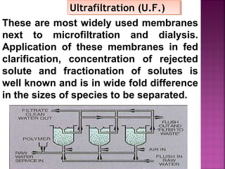
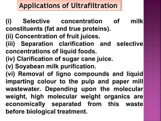
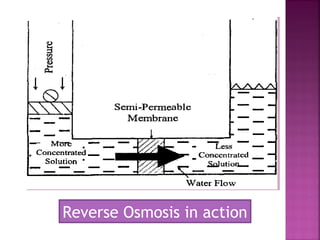
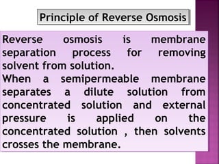
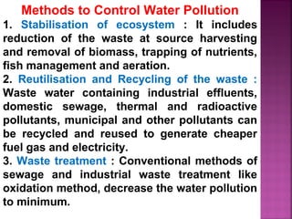
![ Principle - To convert all the soluble hardness
causing constituents into insoluble precipitates
by appropriate chemical treatments and then
removing them.
In this process calculated amounts of Lime
[Ca(OH)2] and Soda (Na2CO3) are added
depending upon the concentration of
impurities.
Reactions of lime with various chemicals in
hard water are as follows:](https://image.slidesharecdn.com/waternew-160407165301/85/Water-87-320.jpg)
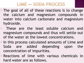
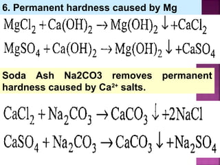
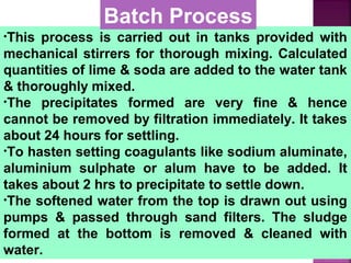

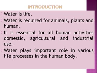
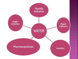
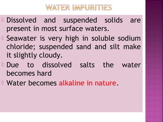
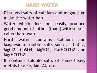
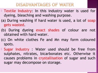
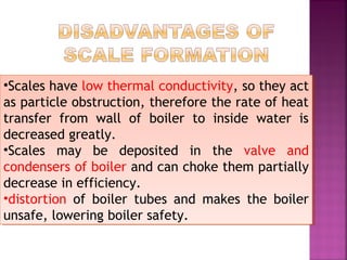
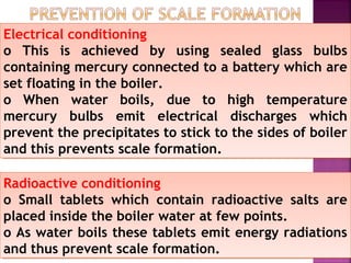
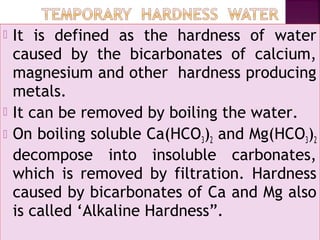
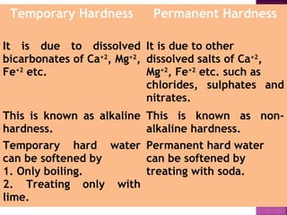
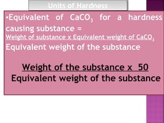
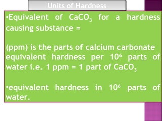
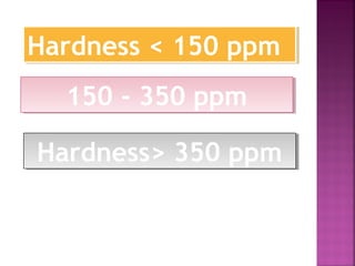
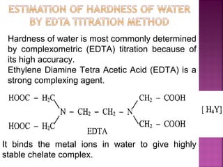
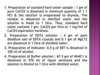
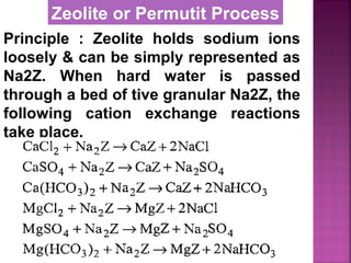
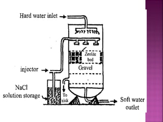
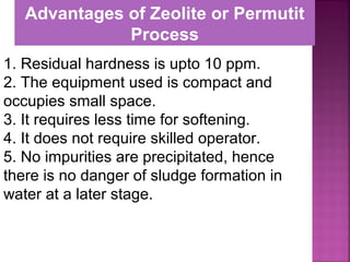
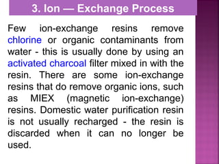
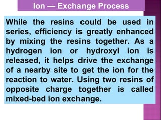
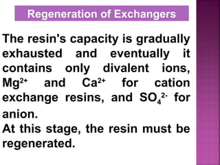
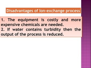
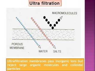
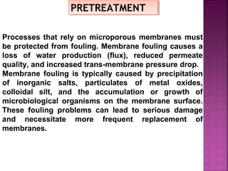
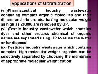
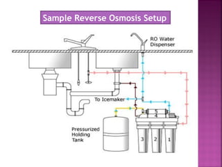
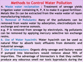
![Permutit is the technical name given
to Sodium Zeolite [Na2Z]
Na2O ∙Al2O3 . xSiO2 . yH2O
where x = 2 to 10, y = 2 to 6
It is also called hydrated sodium
alumino silicates.
It is represented as Na2Z
where Z is zeolite.
Zeolite or Permutit Process](https://image.slidesharecdn.com/waternew-160407165301/85/Water-106-320.jpg)
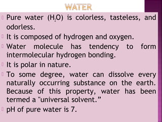
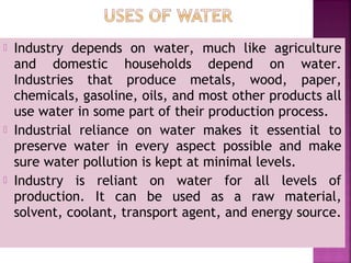
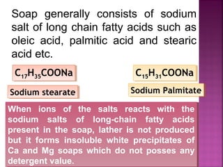
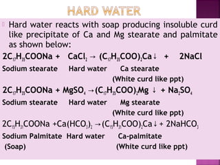
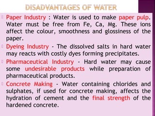
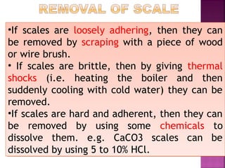
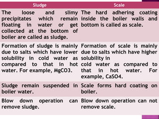
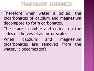
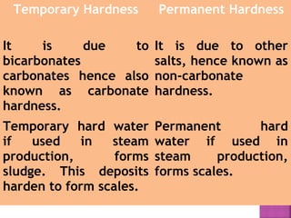
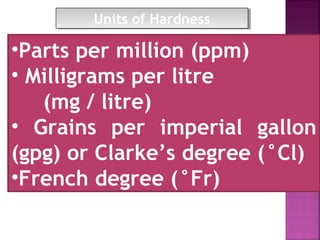
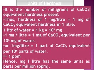
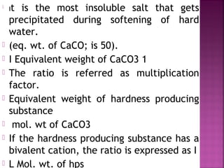
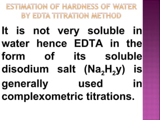
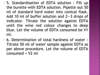
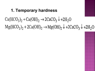
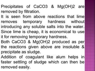
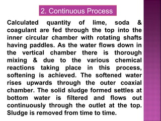
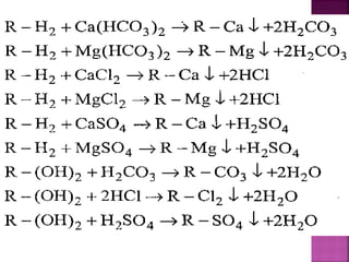
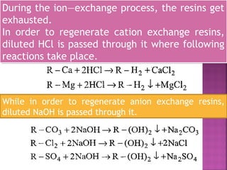
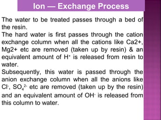
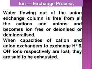
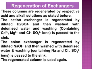
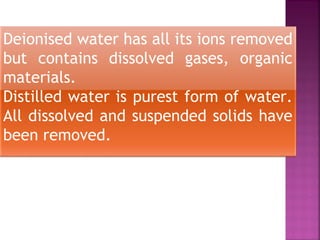
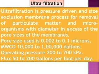
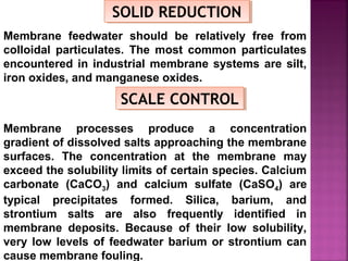
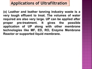
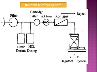
![Cation exchange resins are resins which are capable
of exchanging H+
ions, with other cations.
They contain functional groups like — SO3H, —COOH,
—H etc. They are represented as R—H2.
Commercial cation exchanger is AMBERLITE IR — 120
Anion exchange resins are resins which are capable
of exchanging OH ions, with other anions.
They contain functional groups like — NH2 or —NH as
an integral part of the resin matrix.
When they are treated with dilute NaOH solution,
they act as an anion exchange resins and are
represented as R — (OH)2.
A commercial anion exchange is AMBERLITE [R400]
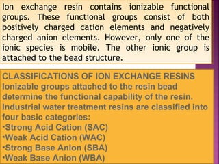
Cation exchange resins are resins which are capable
of exchanging H+
ions, with other cations.
They contain functional groups like — SO3H, —COOH,
—H etc. They are represented as R—H2.
Commercial cation exchanger is AMBERLITE IR — 120
Anion exchange resins are resins which are capable
of exchanging OH ions, with other anions.
They contain functional groups like — NH2 or —NH as
an integral part of the resin matrix.
When they are treated with dilute NaOH solution,
they act as an anion exchange resins and are
represented as R — (OH)2.
A commercial anion exchange is AMBERLITE [R400]](https://image.slidesharecdn.com/waternew-160407165301/85/Water-117-320.jpg)
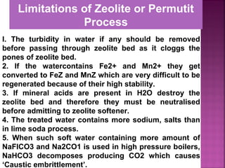
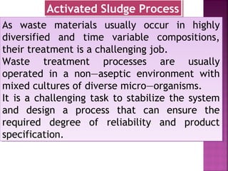
![Determination of COD
1.A known volume of sample is refluxed
with a known excess of standard
potassium dichromate (K2Cr2O7) and dil
H2S04 in presence of a little Ag2SO4
catalyst for 1½ hours.
2.The unreacted K2Cr2O7 is then titrated
against standard Mohr’s salt solution.
[FeSO4 (NH4)2 S046HO2].
3.The O2 equivalent of K2Cr2O7
consumed is taken as a measure of COD.
Determination of COD
1.A known volume of sample is refluxed
with a known excess of standard
potassium dichromate (K2Cr2O7) and dil
H2S04 in presence of a little Ag2SO4
catalyst for 1½ hours.
2.The unreacted K2Cr2O7 is then titrated
against standard Mohr’s salt solution.
[FeSO4 (NH4)2 S046HO2].
3.The O2 equivalent of K2Cr2O7
consumed is taken as a measure of COD.](https://image.slidesharecdn.com/waternew-160407165301/85/Water-175-320.jpg)


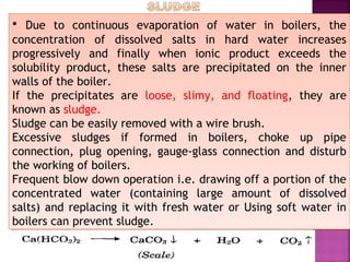
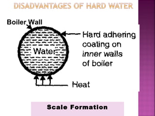
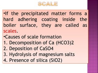
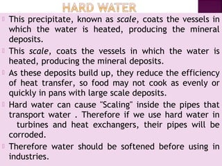
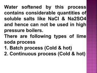
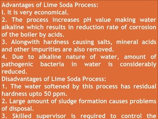
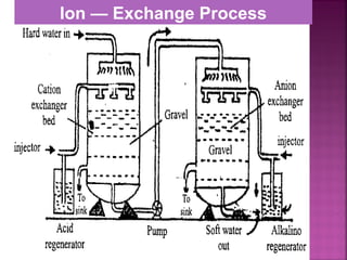
Hard water contains dissolved calcium and magnesium ions that can cause scale buildup and reduce soap efficiency. In boilers, scale forms when calcium and magnesium carbonates and sulfates precipitate out of solution as water is heated. This scale buildup reduces heat transfer efficiency and can damage boiler components over time. Several methods can be used to prevent or remove scale, including frequent blowdowns, adding antiscalants like phosphates, and chemical or mechanical scale removal treatments. Proper treatment of hard water is important for industrial processes and equipment that use water like boilers, cooling systems, and pipes.


