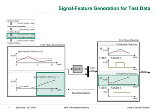
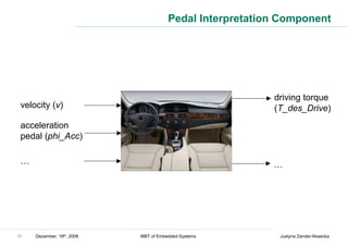
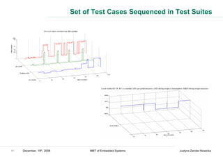
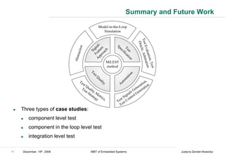
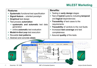
This document summarizes Justyna Zander-Nowicka's doctoral thesis defense on December 19th, 2008 regarding her research on model-based testing of embedded real-time systems in the automotive domain. The thesis proposed a model-based testing approach called MiLEST that uses signal features for automatic test data generation and evaluation. The approach aims to systematically generate functional test cases from models to test embedded systems starting from early development phases.


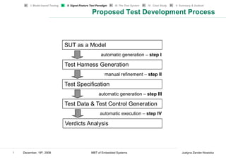


![I. Model-based Testing II. Signal-Feature Test Paradigm III. The Test System IV. Case Study V. Summary & Outlook
Increase Detection and Generation
Detect Increase:
The Increase feature can be detected by analyzing its derivative. This can be
approximated (simplified version of the algorithm!) where the actual signal value
and the past one (backward difference):
feature(kT) = sign [signal (kT) − signal ((k − 1) * T)]
feature(kT) is positive if the signal increases.
Generate Increase:
Example:
11 December, 19th, 2008 MBT of Embedded Systems Justyna Zander-Nowicka](https://image.slidesharecdn.com/zanderengscdfinal-130217192245-phpapp02/85/Zander-eng-scd_final-11-320.jpg)

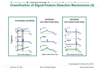


![MSOffice8
Classification of Signal Features based on their Detection
Type
Immediately Identifiable with Identifiable with
identifiable determinate delay indeterminate delay
Detect signal value Detect max / min / Detect duration of
Detect increase / decrease / inflection every single delay
Time-independent
constant Detect peak
Detect continuous signal / Detect impulse
derivative Detect step
Detect linearity (w.r.t. 1st value)
Detect functional relation y = f(x)
Detect causal filter
Detect max-to-date / min-to-date
Detect signal value @ time1 Detect any time Detect step response
Detect time stamp independent features characteristics
Triggered
Detect any time independent over a time interval (rise time, settling
features over a time interval e.g., value @ time, overshoot)
e.g., value @ time1 time of max Detect response delay
e.g., value @ [time1, time2] Detect complete step
30 December, 19th, 2008 MBT of Embedded Systems Justyna Zander-Nowicka](https://image.slidesharecdn.com/zanderengscdfinal-130217192245-phpapp02/85/Zander-eng-scd_final-30-320.jpg)


![Concrete Test Data Variants
phi_Acc2
100
v phi_Acc 90
80
v1 v2 v3 v4 v5 phi_Acc1 phi_Acc2 70
60
phi_Acc
{-10} {-5} {0} {35} {70} [0,10] [90,100] 50
40
30
One factor at a time combination 20
phi_Acc1
SUT inputs 10
0
phi_Acc v 0 2 4 6 8 10 12
time [s]
phi_Acc1 phi_Acc2 v1 v2 v3 v4 v5
iteration1 iteration 2 iteration3 iteration 4 iteration 5 iteration6
1 t0
iterations[n]
time [units]
90
80
2 t1 v5
70
60
3 t2 50
v4
v
40
4 t3 30
20
5 t4 10
v3
0 v2
v1 v1
-10
6 t5
0 2 4 6 8 10 12
time [s]
39 December, 19th, 2008 MBT of Embedded Systems Justyna Zander-Nowicka](https://image.slidesharecdn.com/zanderengscdfinal-130217192245-phpapp02/85/Zander-eng-scd_final-40-320.jpg)


![[English Version]Maker-Ray Product Brochure V3 .pdf](https://cdn.slidesharecdn.com/ss_thumbnails/englishversionmaker-rayproductbrochurev3-260113094444-0156dbdc-thumbnail.jpg?width=640&height=640&fit=bounds)

![DESIGN AND FABRICATION OF THE IBM 90-90 SEAT BELT CLAMP KIA VEHICLE[1].pptx 2...](https://cdn.slidesharecdn.com/ss_thumbnails/designandfabricationoftheibm90-90seatbeltclampkiavehicle1-260116160442-70ff67fc-thumbnail.jpg?width=640&height=640&fit=bounds)


