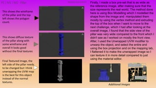
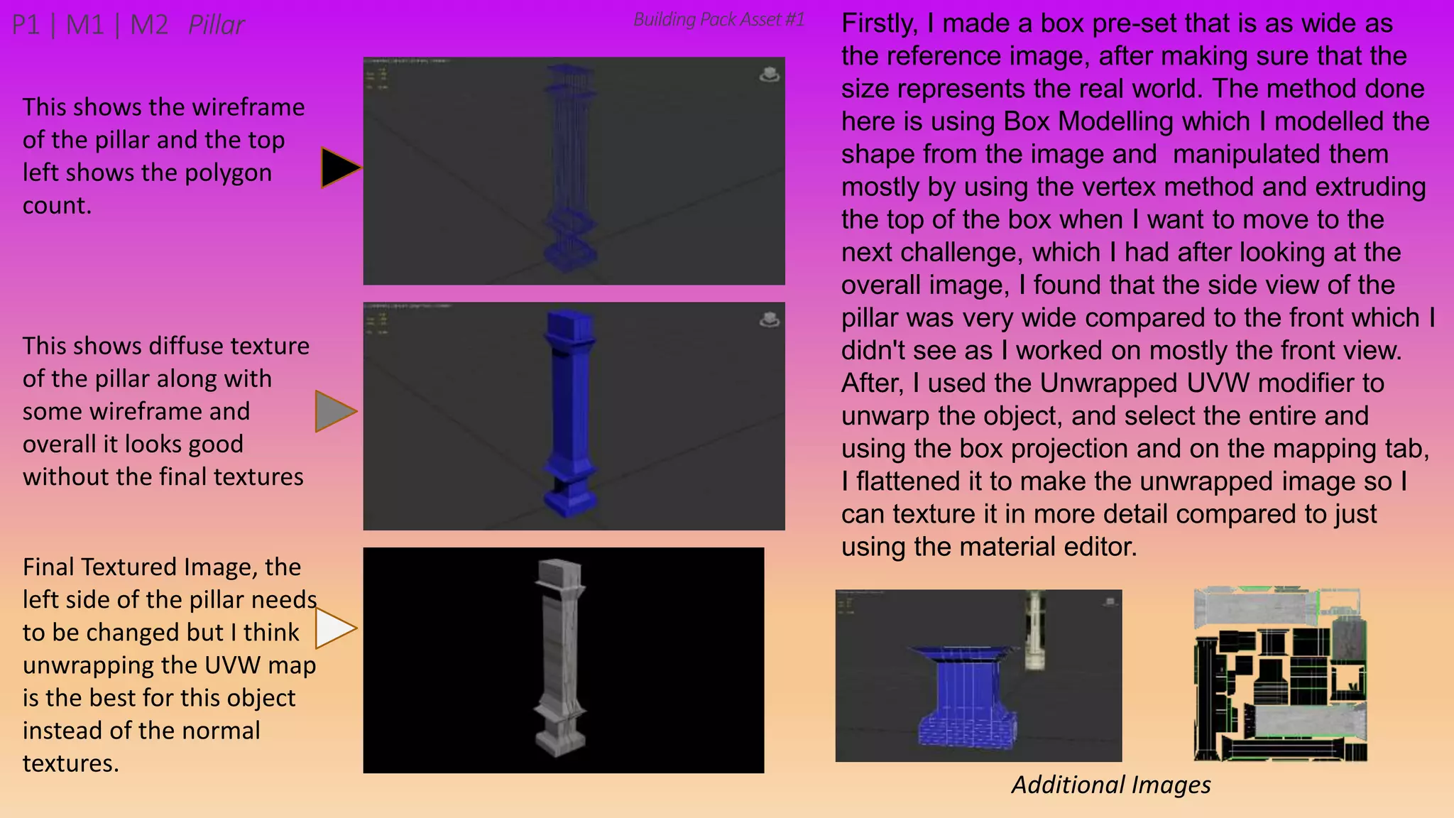
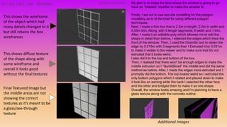
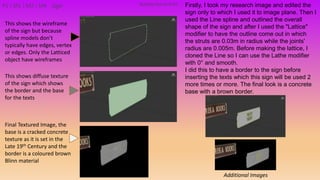
1) The document describes the modeling process for various assets for a building pack in 3ds Max. It includes steps taken to model objects like pillars, signs, fences, stairs, walls and more using techniques like box modeling, spline modeling and modifiers.
2) Wireframes and textures are shown for each asset highlighting modeling details and materials applied. The focus is on accurately representing real-world dimensions and shapes while using appropriate UV mapping and texturing.
3) Processes like extrusion, chamfering, insetting, bridging, latticing and more are employed to model edges, add details and assemble complex shapes from basic geometries.
The document provides details on the modeling process for several modular building assets, including a pillar, window, shop sign, fence, stairs, building front, wall, front pillar, and roof barrier. For each asset, the modeling steps are described, including using techniques like box modeling, extrusion, chamfer, inset, boolean operations, and UV unwrapping. Wireframe and textured images are included to show the progress and results of modeling each asset piece. The goal is to create a set of modular pieces that can be combined to construct different building layouts in 3D.
This document summarizes Leonardo Rueda's CAD/CAM project to model and assemble the parts of a snip using NX software. The individual parts - the handles, grips, and blade - were modeled separately and then assembled together. Finite element analysis was then performed to simulate structural forces on the assembled snip model. Key steps included creating 2D and 3D meshes on parts, applying thickness, and connecting nodes at blade tips. The overall goal was to learn how to design individual parts and assemble them in NX.
Sectional views show the interior details of an object by imagining a cutting plane passes through it. A cutting plane line indicates where the object was cut. Cross hatching in the section shows the cut surface, following rules like not hatching adjacent areas or parallel to features. Section views replace standard views and help dimension interior areas clearly by breaking hatching lines.
Nor Farina Interior Design Technology I PortfolioNorFarinaWafir
This document summarizes an interior design student's model building assignment. The student constructed a 1:25 scale model of a square 10x10 inch one-room house made of cement, boards, and steel wires. The model included structural elements like columns, beams, a foundation, floor, walls and a pitched roof truss. Diagrams show the floor plan, structural layout, and elevations. Photos document the process of measuring, cutting, and assembling the model, which included reinforcement bars, formworks for columns, I-beams on columns, and a roof truss.
Sections are used to show interior details of objects clearly. A cutting plane line indicates where the object was cut to create the section view, and cross hatching shows cut surfaces. There are different types of section views like full, offset, half, broken-out, revolved, and removed sections. Revolved sections rotate a cross section to show features that vary, while removed sections separate the section view from the main view when space is limited.
This document discusses various sectioning conventions used in engineering drawings. It defines different types of sections such as full sections, half sections, and broken-out sections. It describes how to represent features like ribs, spokes, holes and lugs when they are cut by the sectioning plane. Guidelines are provided for cross-hatching cut surfaces, showing hidden details, and aligning non-symmetrical elements in section views. The document also covers conventions for thin materials, breaks, and other techniques to clarify interior features in sectional views.
A section view shows internal or hidden parts of an object by depicting a cut through the object. There are several types of section views including full sections, which cut fully through the object, and half sections, which cut halfway. Section views are useful for visualizing internal features and how parts fit together in assemblies. Hatching is used in section views to indicate the cut surface and different patterns represent various materials.
The document summarizes a team's design report for a project to build a powered mechanism to intercept and reflect laser beams onto a target using a movable mirror. The mechanism must work within the constraints of a playing field with 4 lanes and detect which lane a laser is in to position the mirror accordingly. The team developed 2D linkage models in SolidWorks and analyzed different designs based on criteria like power consumption, volume, and transmission angle deviation to select a final design. Design 1 was chosen as the best design since it had the lowest power consumption and volume and smallest transmission angle deviations. Details of the selected final 4-bar linkage design and its performance are presented.
The document provides a production log for a games design student's project creating a level for a port-based game. Over several dates, the student modeled 3D assets like buildings, containers, and roads; textured models; and set up a fly-through camera path. The log details the modeling steps taken, such as using primitive tools to create basic shapes and refining models.
The document provides a production log for a student's games design project creating a level for a port town. It details the modeling process over several weeks, including importing imagery, mapping out the level shape, and constructing buildings and structures like warehouses, cargo containers, and roads. The student surfaces the models, sets up a fly-through camera path in the game engine, adds sky and environment effects, and renders the final video.
The document provides summaries of 3D models created by the author over several months using a 3D modeling software. Some of the models created include a bottle, mug, small house, chair, table, cactuses, horse trough, barrel, windmill, rifles, chandelier, tracks, fence, wagon, gold bar, stairs, bench, fort walls and entrance, church, saloon, medium and large houses, barn, and lantern. The author utilizes basic 3D primitives like boxes, cylinders, and discs, along with modeling techniques like Boolean operations and point manipulation to sculpt the shapes and assemble the components of each model.
The document provides summaries of 3D models created in a 3D modeling software, including a bottle, mug, small house, chair, table, cactuses, horse trough, barrel, windmill, rifles, chandelier, tracks, fence, wagon, gold bar, stairs, bench, fort walls and entrance, church, saloon, medium and large houses, barn, lantern, and extras like cards and posters. Each model is summarized in 1-2 sentences describing the key shapes and modeling techniques used to create the object.
1) The document describes the process taken to create levels for a game. Key steps included designing backgrounds, objects, and currency counters using shapes and the pencil tool.
2) Common elements like borders and currency displays were reused across levels by copying and pasting, then modifying colors or sizes as needed.
3) Some objects had to be recreated at larger sizes due to quality issues when simply enlarging the original.
4) Additional screens like a shop were created by building on the designs of previous screens.
The document provides details on modeling a treasure chest, including skills required, a Gantt chart timeline, reference image, and descriptions of modeling different parts of the chest. It discusses modeling the leg, box, base, lid, lid details, lock, final model setup, and texturing process. The modeling was done in 3ds Max and texturing in Photoshop. The document concludes with an evaluation of how the project met the assignment specifications.
The document provides details on modeling 3D environments and objects for a ship in a 3D modeling program. It describes how each component was created using basic shapes like cylinders and cubes, then modified with tools like subtraction and mirroring. Key areas modeled include a hallway with exits, panels and pipes; bedroom furniture like beds and crates; tables and chairs for different rooms; and ship areas like the cockpit, crew quarters, medbay, engine room and garage. Processes like using multiple polygons, subdivision and texture mapping are also outlined.
The document describes the process of modeling a 3D cityscape in steps. It begins with setting preferences and initially designing the bottom layer to establish size. Basic shapes are added to represent building placement and shape. More complex shapes and designs are added, like walls surrounding a park. Details are added to structures like a fast food parlor and outdoor dining area. Multiple structures are created, including a multi-story car park with ramps and walls. Other buildings follow like a burger shop, park with basketball courts, playground, and apartment blocks with windows. Texture and materials are added and the map is populated with more buildings until half is complete.
The document is an intermediate tutorial for Google SketchUp. It introduces Bezier curves, which allow for complex shapes. A Ruby script called bezierspline.zip adds Bezier curve tools. There are different types of Bezier curves - classic, polyline, uniform B-spline, and cubic Bezier. The document compares each type using a sample shape and finds the cubic Bezier curve the most predictable and controllable. It then demonstrates using the cubic Bezier curve to model the profile of an office table edge.
The document is an intermediate tutorial for Google SketchUp. It introduces Bezier curves, which allow for complex shapes. A Ruby script called bezierspline.zip must be downloaded and installed to access these tools. There are different types of Bezier curves - classic, polyline, uniform B-spline, and cubic Bezier. The document compares each type and determines the cubic Bezier curve is the most predictable and controllable. It then demonstrates using the cubic Bezier curve tool to model the profile of an office table edge.
The document contains descriptions of several 3D modeling projects completed by Jacob Grimes using advanced surfacing techniques in SolidWorks:
1) A face mask with lofted surfaces, boundary surfaces, surface extrusion and trimming.
2) A loft and mirror exercise using loft surfaces, fillets and thickness.
3) A funnel modeled with lofted profiles, shelling and circular patterns.
4) A candle holder with revolved surfaces and a swept surface for the midsection.
5) A linear pattern exercise using pattern, move/copy and combine features.
6) An original go-kart design with a gas and braking system controlled from the steering wheel.
Allison created a pixel art video game using Photoshop. She drew the main character pixel by pixel and created three different settings for the game. Each setting had obstacles for the character to navigate and clues in the form of newspaper clippings. Creating the clippings involved cutting the paper into separate layers to look old and torn. Allison then animated the character moving through each setting frame by frame. When finding clues, she made the newspaper clippings and a block with dots visible. Finally, she added music in Premiere Pro and exported the completed game.
1) The document describes how to construct basic and advanced tessellations through step-by-step processes. For the basic tessellation, a master tile is created using rotations and is then tessellated using repeated rotations of 60 and 180 degrees. For the advanced tessellation, a master tile is created using a translation and glide reflection and is tessellated through repeated reflections and translations.
2) Tessellations demonstrate mathematical concepts like isometries and can engage students in exploring geometry. Regular tessellations by hexagons, for example, are found in nature in honeycombs.
3) Tessellations have uses beyond mathematics, such as in stained glass windows where abstract designs were used
The document summarizes the process of modeling a spaceship interior in 3D modeling software. It describes how the author built out the main areas first before walls to have an unobstructed view. Key areas modeled included the captain's office, stairways, walkways, rooms, computer desk, bathroom fixtures like toilets and cubicles, seats based on Star Trek designs, beds, engine room with complex parts, and lastly storage shelves. Basic shapes were modified using tools like extrude, bevel, drill to achieve realistic designs for furnishings.
This document contains a photography project with contact sheets and edited images. The student took photos of architecture around York and edited them using techniques like changing to black and white, adding fog, replacing skies, and combining images. They discuss specific edited images and the techniques used. Feedback praised the creative effects but suggested some images could be improved with adjustments to curves, backgrounds, or color vibrancy. The student reflected that they achieved their goal of fine art images of architecture and learned photography skills like using manual mode and post-production editing.
The student worked on assembling their tree bookshelf project. They measured, cut, and joined various parts using tools like saws, drills, and clamps. This included cutting the base, sides, and shelf pieces to size. Holes were drilled and parts were joined with glue and screws. The student encountered some challenges along the way and made adjustments to their plan and process based on what they were learning.
This document summarizes the 19 step process for creating a billboard advertisement in Photoshop. It involves removing a subject from the original background, adjusting the lighting and shadows, adding effects to make the subject look natural on a new background, placing chains and cracks on the wall to make the chains look anchored, and positioning text, logos and the subject on the backdrop. Each step is explained in detail with screenshots showing the editing tools and adjustments used at each phase of design.
The document outlines the 19 step process to create a billboard advertisement through photoshop. It involves removing a subject from the original background, adjusting the lighting and placement on a new background, adding chains and cracks to make them look connected to the background, and placing text and logos. Key steps include selecting and adjusting the subject, adding shadows and effects to blend elements, and precisely positioning all graphical elements on the final advertisement design.
The document describes the process taken to create several motion posters in Photoshop and After Effects. Key steps include:
1) Sketching ideas in Photoshop, cleaning up sketches, and separating elements into layers for animation.
2) Importing layers into After Effects and using the puppet pin tool to animate elements without frame-by-frame work.
3) Creating additional motion posters using text and effects like neon lighting, blurring, and typewriter animations to emulate real neon signs.
4) Combining techniques like hand-drawn art, neon text, and video overlays to create final composite posters.
Kallum Sykes created a multi-layered digital image depicting a train scene in a picture frame hanging on a grey wall. He added realistic shadows and textures to elements like the picture frame, train, sky, and ground. Kallum cut out and arranged stock images to compose the scene, such as a train from a museum photo and landscape elements. He extended and customized parts of the image, like the railway tracks, to complete the scene within the frame. Kallum added floorboards and a skirting board using shapes and shadows to enhance realism.
QR Secure: A Hybrid Approach Using Machine Learning and Security Validation F...AlexanderRichford
QR Secure: A Hybrid Approach Using Machine Learning and Security Validation Functions to Prevent Interaction with Malicious QR Codes.
Aim of the Study: The goal of this research was to develop a robust hybrid approach for identifying malicious and insecure URLs derived from QR codes, ensuring safe interactions.
This is achieved through:
Machine Learning Model: Predicts the likelihood of a URL being malicious.
Security Validation Functions: Ensures the derived URL has a valid certificate and proper URL format.
This innovative blend of technology aims to enhance cybersecurity measures and protect users from potential threats hidden within QR codes 🖥 🔒
This study was my first introduction to using ML which has shown me the immense potential of ML in creating more secure digital environments!
Conversational agents, or chatbots, are increasingly used to access all sorts of services using natural language. While open-domain chatbots - like ChatGPT - can converse on any topic, task-oriented chatbots - the focus of this paper - are designed for specific tasks, like booking a flight, obtaining customer support, or setting an appointment. Like any other software, task-oriented chatbots need to be properly tested, usually by defining and executing test scenarios (i.e., sequences of user-chatbot interactions). However, there is currently a lack of methods to quantify the completeness and strength of such test scenarios, which can lead to low-quality tests, and hence to buggy chatbots.
To fill this gap, we propose adapting mutation testing (MuT) for task-oriented chatbots. To this end, we introduce a set of mutation operators that emulate faults in chatbot designs, an architecture that enables MuT on chatbots built using heterogeneous technologies, and a practical realisation as an Eclipse plugin. Moreover, we evaluate the applicability, effectiveness and efficiency of our approach on open-source chatbots, with promising results.
What is an RPA CoE? Session 2 – CoE RolesDianaGray10
In this session, we will review the players involved in the CoE and how each role impacts opportunities.
Topics covered:
• What roles are essential?
• What place in the automation journey does each role play?
Speaker:
Chris Bolin, Senior Intelligent Automation Architect Anika Systems
GlobalLogic Java Community Webinar #18 “How to Improve Web Application Perfor...GlobalLogic Ukraine
Під час доповіді відповімо на питання, навіщо потрібно підвищувати продуктивність аплікації і які є найефективніші способи для цього. А також поговоримо про те, що таке кеш, які його види бувають та, основне — як знайти performance bottleneck?
Відео та деталі заходу: https://bit.ly/45tILxj
Northern Engraving | Modern Metal Trim, Nameplates and Appliance PanelsNorthern Engraving
What began over 115 years ago as a supplier of precision gauges to the automotive industry has evolved into being an industry leader in the manufacture of product branding, automotive cockpit trim and decorative appliance trim. Value-added services include in-house Design, Engineering, Program Management, Test Lab and Tool Shops.
As AI technology is pushing into IT I was wondering myself, as an “infrastructure container kubernetes guy”, how get this fancy AI technology get managed from an infrastructure operational view? Is it possible to apply our lovely cloud native principals as well? What benefit’s both technologies could bring to each other?
Let me take this questions and provide you a short journey through existing deployment models and use cases for AI software. On practical examples, we discuss what cloud/on-premise strategy we may need for applying it to our own infrastructure to get it to work from an enterprise perspective. I want to give an overview about infrastructure requirements and technologies, what could be beneficial or limiting your AI use cases in an enterprise environment. An interactive Demo will give you some insides, what approaches I got already working for real.
Keywords: AI, Containeres, Kubernetes, Cloud Native
Event Link: https://meine.doag.org/events/cloudland/2024/agenda/#agendaId.4211
Introducing BoxLang : A new JVM language for productivity and modularity!Ortus Solutions, Corp
Just like life, our code must adapt to the ever changing world we live in. From one day coding for the web, to the next for our tablets or APIs or for running serverless applications. Multi-runtime development is the future of coding, the future is to be dynamic. Let us introduce you to BoxLang.
Dynamic. Modular. Productive.
BoxLang redefines development with its dynamic nature, empowering developers to craft expressive and functional code effortlessly. Its modular architecture prioritizes flexibility, allowing for seamless integration into existing ecosystems.
Interoperability at its Core
With 100% interoperability with Java, BoxLang seamlessly bridges the gap between traditional and modern development paradigms, unlocking new possibilities for innovation and collaboration.
Multi-Runtime
From the tiny 2m operating system binary to running on our pure Java web server, CommandBox, Jakarta EE, AWS Lambda, Microsoft Functions, Web Assembly, Android and more. BoxLang has been designed to enhance and adapt according to it's runnable runtime.
The Fusion of Modernity and Tradition
Experience the fusion of modern features inspired by CFML, Node, Ruby, Kotlin, Java, and Clojure, combined with the familiarity of Java bytecode compilation, making BoxLang a language of choice for forward-thinking developers.
Empowering Transition with Transpiler Support
Transitioning from CFML to BoxLang is seamless with our JIT transpiler, facilitating smooth migration and preserving existing code investments.
Unlocking Creativity with IDE Tools
Unleash your creativity with powerful IDE tools tailored for BoxLang, providing an intuitive development experience and streamlining your workflow. Join us as we embark on a journey to redefine JVM development. Welcome to the era of BoxLang.
Getting the Most Out of ScyllaDB Monitoring: ShareChat's TipsScyllaDB
ScyllaDB monitoring provides a lot of useful information. But sometimes it’s not easy to find the root of the problem if something is wrong or even estimate the remaining capacity by the load on the cluster. This talk shares our team's practical tips on: 1) How to find the root of the problem by metrics if ScyllaDB is slow 2) How to interpret the load and plan capacity for the future 3) Compaction strategies and how to choose the right one 4) Important metrics which aren’t available in the default monitoring setup.
The Department of Veteran Affairs (VA) invited Taylor Paschal, Knowledge & Information Management Consultant at Enterprise Knowledge, to speak at a Knowledge Management Lunch and Learn hosted on June 12, 2024. All Office of Administration staff were invited to attend and received professional development credit for participating in the voluntary event.
The objectives of the Lunch and Learn presentation were to:
- Review what KM ‘is’ and ‘isn’t’
- Understand the value of KM and the benefits of engaging
- Define and reflect on your “what’s in it for me?”
- Share actionable ways you can participate in Knowledge - - Capture & Transfer
Connector Corner: Seamlessly power UiPath Apps, GenAI with prebuilt connectorsDianaGray10
Join us to learn how UiPath Apps can directly and easily interact with prebuilt connectors via Integration Service--including Salesforce, ServiceNow, Open GenAI, and more.
The best part is you can achieve this without building a custom workflow! Say goodbye to the hassle of using separate automations to call APIs. By seamlessly integrating within App Studio, you can now easily streamline your workflow, while gaining direct access to our Connector Catalog of popular applications.
We’ll discuss and demo the benefits of UiPath Apps and connectors including:
Creating a compelling user experience for any software, without the limitations of APIs.
Accelerating the app creation process, saving time and effort
Enjoying high-performance CRUD (create, read, update, delete) operations, for
seamless data management.
Speakers:
Russell Alfeche, Technology Leader, RPA at qBotic and UiPath MVP
Charlie Greenberg, host
ScyllaDB is making a major architecture shift. We’re moving from vNode replication to tablets – fragments of tables that are distributed independently, enabling dynamic data distribution and extreme elasticity. In this keynote, ScyllaDB co-founder and CTO Avi Kivity explains the reason for this shift, provides a look at the implementation and roadmap, and shares how this shift benefits ScyllaDB users.
From Natural Language to Structured Solr Queries using LLMsSease
This talk draws on experimentation to enable AI applications with Solr. One important use case is to use AI for better accessibility and discoverability of the data: while User eXperience techniques, lexical search improvements, and data harmonization can take organizations to a good level of accessibility, a structural (or “cognitive” gap) remains between the data user needs and the data producer constraints.
That is where AI – and most importantly, Natural Language Processing and Large Language Model techniques – could make a difference. This natural language, conversational engine could facilitate access and usage of the data leveraging the semantics of any data source.
The objective of the presentation is to propose a technical approach and a way forward to achieve this goal.
The key concept is to enable users to express their search queries in natural language, which the LLM then enriches, interprets, and translates into structured queries based on the Solr index’s metadata.
This approach leverages the LLM’s ability to understand the nuances of natural language and the structure of documents within Apache Solr.
The LLM acts as an intermediary agent, offering a transparent experience to users automatically and potentially uncovering relevant documents that conventional search methods might overlook. The presentation will include the results of this experimental work, lessons learned, best practices, and the scope of future work that should improve the approach and make it production-ready.
"What does it really mean for your system to be available, or how to define w...Fwdays
We will talk about system monitoring from a few different angles. We will start by covering the basics, then discuss SLOs, how to define them, and why understanding the business well is crucial for success in this exercise.
What is an RPA CoE? Session 1 – CoE VisionDianaGray10
In the first session, we will review the organization's vision and how this has an impact on the COE Structure.
Topics covered:
• The role of a steering committee
• How do the organization’s priorities determine CoE Structure?
Speaker:
Chris Bolin, Senior Intelligent Automation Architect Anika Systems
Dandelion Hashtable: beyond billion requests per second on a commodity serverAntonios Katsarakis
This slide deck presents DLHT, a concurrent in-memory hashtable. Despite efforts to optimize hashtables, that go as far as sacrificing core functionality, state-of-the-art designs still incur multiple memory accesses per request and block request processing in three cases. First, most hashtables block while waiting for data to be retrieved from memory. Second, open-addressing designs, which represent the current state-of-the-art, either cannot free index slots on deletes or must block all requests to do so. Third, index resizes block every request until all objects are copied to the new index. Defying folklore wisdom, DLHT forgoes open-addressing and adopts a fully-featured and memory-aware closed-addressing design based on bounded cache-line-chaining. This design offers lock-free index operations and deletes that free slots instantly, (2) completes most requests with a single memory access, (3) utilizes software prefetching to hide memory latencies, and (4) employs a novel non-blocking and parallel resizing. In a commodity server and a memory-resident workload, DLHT surpasses 1.6B requests per second and provides 3.5x (12x) the throughput of the state-of-the-art closed-addressing (open-addressing) resizable hashtable on Gets (Deletes).
LF Energy Webinar: Carbon Data Specifications: Mechanisms to Improve Data Acc...DanBrown980551
This LF Energy webinar took place June 20, 2024. It featured:
-Alex Thornton, LF Energy
-Hallie Cramer, Google
-Daniel Roesler, UtilityAPI
-Henry Richardson, WattTime
In response to the urgency and scale required to effectively address climate change, open source solutions offer significant potential for driving innovation and progress. Currently, there is a growing demand for standardization and interoperability in energy data and modeling. Open source standards and specifications within the energy sector can also alleviate challenges associated with data fragmentation, transparency, and accessibility. At the same time, it is crucial to consider privacy and security concerns throughout the development of open source platforms.
This webinar will delve into the motivations behind establishing LF Energy’s Carbon Data Specification Consortium. It will provide an overview of the draft specifications and the ongoing progress made by the respective working groups.
Three primary specifications will be discussed:
-Discovery and client registration, emphasizing transparent processes and secure and private access
-Customer data, centering around customer tariffs, bills, energy usage, and full consumption disclosure
-Power systems data, focusing on grid data, inclusive of transmission and distribution networks, generation, intergrid power flows, and market settlement data
In the realm of cybersecurity, offensive security practices act as a critical shield. By simulating real-world attacks in a controlled environment, these techniques expose vulnerabilities before malicious actors can exploit them. This proactive approach allows manufacturers to identify and fix weaknesses, significantly enhancing system security.
This presentation delves into the development of a system designed to mimic Galileo's Open Service signal using software-defined radio (SDR) technology. We'll begin with a foundational overview of both Global Navigation Satellite Systems (GNSS) and the intricacies of digital signal processing.
The presentation culminates in a live demonstration. We'll showcase the manipulation of Galileo's Open Service pilot signal, simulating an attack on various software and hardware systems. This practical demonstration serves to highlight the potential consequences of unaddressed vulnerabilities, emphasizing the importance of offensive security practices in safeguarding critical infrastructure.
1. P1 | M1 | M2 Firstly, I made a box pre-set that is as wide as
the reference image, after making sure that the
size represents the real world. The method done
here is using Box Modelling which I modelled the
shape from the image and manipulated them
mostly by using the vertex method and extruding
the top of the box when I want to move to the
next challenge, which I had after looking at the
overall image, I found that the side view of the
pillar was very wide compared to the front which I
didn't see as I worked on mostly the front view.
After, I used the Unwrapped UVW modifier to
unwarp the object, and select the entire and
using the box projection and on the mapping tab,
I flattened it to make the unwrapped image so I
can texture it in more detail compared to just
using the material editor.
This shows the wireframe
of the pillar and the top
left shows the polygon
count.
This shows diffuse texture
of the pillar along with
some wireframe and
overall it looks good
without the final textures
Final Textured Image, the
left side of the pillar needs
to be changed but I think
unwrapping the UVW map
is the best for this object
instead of the normal
textures.
Additional Images
Pillar Building PackAsset#1
2. P1 | M1 | M2 | M4 My plan is to make the face where the window is going to go
have an "Inseted" modifier to make the window fit.
Firstly, I set out to use extrude modelling for the polygon
modelling as to fit the brief for using different polygon
techniques.
Next, I made a thin box that is 2.5m in length, 2.0m in width and
0.05m thin. Along, with 5 length segments, 6 width and 1 thin.
After, I made it an editable poly which allowed me to edit the
shape in detail than before, I selected the edges which lines the
front of the window. Then, I used the Chamfer tool to widen the
edge by 0.015m with 3 segments then I Extruded it by 0.031m
to make it visible to the viewer and to make sure that it's not
extruded that it looks weird.
I also did it to the top and bottom of the box.
Then, I realised that there won't be enough edges to make the
middle extrusion so I “QuickSliced” the middle and did the same
method as before. After, I made the edges more extruded and I
promptly did the bottom. The top looked weird so I extruded the
only bottom polygons which I rotated and placed down to make
it look like an awning while the back I selected the other face
and the other and bridged them to make it as one shape.
Overall, the window looks amazing and I'm planning to have a
glass texture along with the concrete outline.
This shows the wireframe
of the object which had
many details changed to it
but still retains the box
wireframes
This shows diffuse texture
of the shape along with
some wireframe and
overall it looks good
without the final textures
Final Textured Image but
the middle areas are not
showing the correct
textures as it’s meant to be
a glass/see-through
texture
Additional Images
Building PackAsset#2Window
3. P2 | M1 | M2 | M4 Firstly, I took my research image and edited the
sign only to which I used it to image plane. Then I
used the Line spline and outlined the overall
shape of the sign and after I used the "Lattice"
modifier to have the outline come out in which
the struts are 0.03m in radius while the joints'
radius are 0.005m. Before making the lattice, I
cloned the Line so I can use the Lathe modifier
with 0° and smooth.
I did this to have a border to the sign before
inserting the texts which this sign will be used 2
more times or more. The final look is a concrete
base with a brown border.
This shows the wireframe
of the sign but because
spline models don’t
typically have edges, vertex
or edges. Only the Latticed
object have wireframes
This shows diffuse texture
of the sign which shows
the border and the base
for the texts
Final Textured Image, the
base is a cracked concrete
texture as it is set in the
Late 19th Century and the
border is a coloured brown
Blinn material
Additional Images
Building PackAsset#3Sign
4. Firstly, I got my reference images and image planed it into the
scene. After, I used the Line Spline Method to trace of the fence
then I Lathed it fully with 360° radius with 6 segments to make it
not rounded. Then I used array to have
multiple of the same object to fit the fence, with 2D having 8
fences and they are 2m apart on the X-axis. I used Crease to
get the polygon count from 416 to 224 for the poles only.
After, I used Line & Arcs to get the right shape for the fence top
then I scaled it down to fit the top of the fence post but I still
have the base missing so then I changed my viewport to the top
and used the rectangle spline to make the base for the top and
the corner radius of 0.035m then I used the Lathe
to have a base then I used Edit Poly to extrude the base by
0.04m. Then I applied my textures.
But, the fence goes up the stairs so I need the base to tilt up
and back for the stairs and the fence posts has to be in
ascending order which can be done with the Array tool but that
has to be done when the stairs is built.
This shows the diffuse
texture of the unfinished
fence which shows the
fence which can be
duplicated in the final
building.
This shows wireframe of
the fence with the sign
post, base and the fence
top.
Final Textured Image, all of
the objects are textured by
the same metal texture but
with different glossiness
and lightness both in
Photoshop and in 3ds Max
Additional Images
Building PackAsset#4P2 | M1 | M2 Fence
5. P1 | M1 | M2
Additional Images
Building PackAsset#5 First, I got my image and the measurements from my research
file then I used the box model to shape the box to the height and
width of each individual stairs which is 0.35m in height, 0.889m
in width and 3m in length.
After, I used the array tool to create 5 "stairs" which was 0.89m
apart with 0.35m high each. But I will, use this
model to model my fence then it will become combined.
After, I used the modifier Tessellate with a 2.1 value to make the
stairs more broken and cracked up to fit the spec. For the very
first stairs, I used the Inset tool to make a dip on the stairs to
show it’s age.
Afterwards, I selected the first stair and Unwrapped them with
Normal Mapping which I added the texture on top of and used
the unwrapped file as the material. With the other stairs, I
unwrapped them but using the Flattened Mapping then added
the texture on top of them
Below is the different unwrapping maps for the different stairs.
The image shows the
wireframe view of the
stairs, you can see how the
Tessellation affected the
box shape
<- Flatten Map | Normal Map ->
Both maps unwrapped &
textured
The image shows the
normal view which shows
how the different texturing
shows up with the first
stairs and the rest
Final rendered view of the
stairs
Stairs
6. The whole piece is actually grouped. Using the reference image,
I created a box which to create the wall where the window will
be placed and shaped the box with the reference image using
Extrution & QuickSlice to create the window base and the place
where the sign will be placed. Afterwards, I used the UVW Map
modifier to change the alignment as the texture is stretched by
default so changing it to Y fixed the stretched texture with the
Box Mapping. I did the same with the other side. With the
middle piece where the door will be present, I created a very
thin Box as the wall and used QuickSlice to add polygons to be
extruded with the sign placement. Again, I used the same
method as before with UVW Map, it fixed the stretching. With
the door, I used a very thin box (0.03m wide) and with some
polygons, I extruded them a bit to add depth to the door. Finally,
I used Inset to the middle too again add depth and details along
witth using QS & Extrude and using the rotation tool to point
them towards the Inseted area.
Building PackAsset#6P1 | M1 | M2 Front
This shows the diffuse
texture of the front with
some of the textures
showing up.
This shows wireframe of
the front, all objects are
grouped. It shows the
different objects which
makes the front.
Final Textured Image, all of
the objects which makes
the front are individually
textured and UVW
mapped to fix the
stretched texturing
Additional Images
Images show the wireframe and diffuse view of both the door and the pillar pieces for the front
7. The walls is the simplest object in the
building pack however, I am planning
to add foliage and more windows at
the back of the building as I’m using
this wall for each side of the building
expect the front. With the wall, I used
UVW Map to fix the tiling, with Box
Mapping with a Z-axis alignment and
a 3x3x3 UVW tile value. The wall is
set to real world scale.
Building PackAsset#7P1 | M1 | M2 Wall
This shows the final
rendered image
This shows normal view of
the side wall
8. First, I placed a box model which fit the
height of the building, then I extruded
the top polygon to about a couple of
centimetres to act as the storefront and
to have a “roof” for the pillars that I
placed below it, afterwards I selected
the polygons surrounding it and rotated
it 45° to make sure that it faces the
player and to see what the store is.
Afterwards, I used the window XREF to
see where it will be relative to the front,
then I added edges below the windows,
I then titled and extruded them to make
it look like the window is resting on the
extruded edge.
Building PackAsset#8P1 | M1 | M2 Front Pillar
This shows the final
rendered image
This shows normal view of
the side wall
Final rendered view of the
stairs
9. Firstly, I measured the length of the roof to make
sure that the measurement is correct. After, I
created a long box modelled barrier that is a
very cm thick. Firstly, I tried to create the holes
by manually creating edges and deleting the
polygons inside the edges but that was very time
consuming, instead I used ProBoolean. I created
a cylindrical shape that is small enough to be
similar to the roof design that I am taking
inspiration to, after I created an “X” shaped
object by creating 4 box shapes and rotating
them to form an X then grouping them. With the
two shapes completed, I positioned them along
the barrier with the holes in one side and the X
on the other. I then used “Array” to fill the
barrier. By using ProBoolean and clicking on Star
Picking, I selected all the objects in the barrier
and the holes started to appear.
Building PackAsset#9P1 | M1 | M2 Roof Barrier
This shows the final
rendered image
This shows normal view of
the side wall
Final rendered view of the
stairs
10. Using Box Modelling, I created a box with
2x2 subdivisions then I used Extrusion on
the polygon face in the middle a couple of
cm in which I stopped extruding and
added another polygon to extrude even
further. Then, I used the vertices of each
corners and extended them a bit to look
like a pillar then with the polygon still in
the middle, I extruded them a bit further
and the whole model was completed. For
the Front Roof Pillars I changed the shape
by changing the Scale to look like a 2D
shape for the front. With the Pillars
completed, I duplicated them and placed
them at each corner where the barriers
terminates and with the front pillars, I
scaled them and placed both of them on
the side of the centre barrier.
Building PackAsset#10P1 | M1 | M2 Roof Pillars
This shows the final
rendered image
This shows normal view of
the side wall
Final rendered view of the
stairs
11. Using a Image Plane of a lamp, I traced
the pole in which the lamp is going to be
held. I used a Line Spine and used the
arc to model where the lamp will be
held up and where it will be sticking to
the wall.
After, I created a small circle spline and
used the Loft tool which created the
small circle with the line spine.
For the “Glass” Lamp itself, I used a
cylindrical shape which I deleted the top
polygons to let light out and I used
Vertex editing to make the bottom more
of a smooth bottom.
Building PackAsset#11P2 | M1 | M2 Lamp
This shows the final
rendered image
This shows normal view of
the side wall
Final rendered view of the
stairs