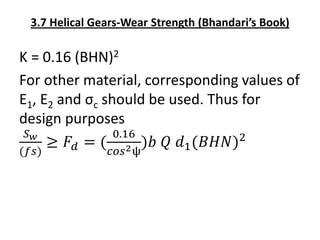
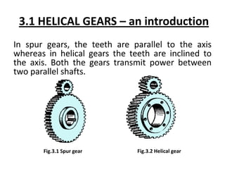
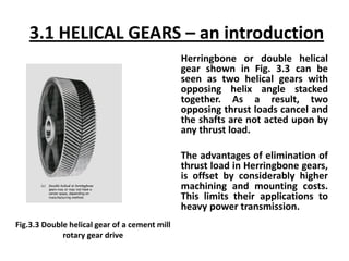
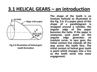
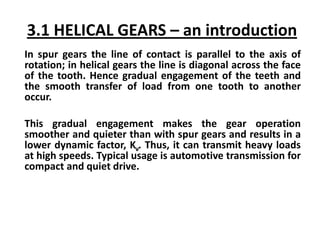
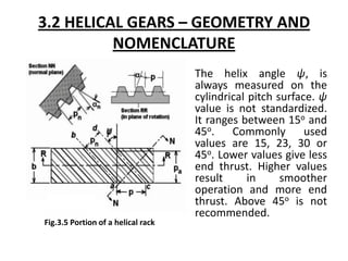
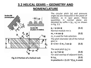
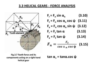
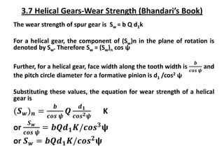
2. 3.1 HELICAL GEARS – an introduction
In spur gears, the teeth are parallel to the axis
whereas in helical gears the teeth are inclined to
the axis. Both the gears transmit power between
two parallel shafts.
Fig.3.1 Spur gear Fig.3.2 Helical gear
3. 3.1 HELICAL GEARS – an introduction
Herringbone or double helical
gear shown in Fig. 3.3 can be
seen as two helical gears with
opposing helix angle stacked
together. As a result, two
opposing thrust loads cancel and
the shafts are not acted upon by
any thrust load.
The advantages of elimination of
thrust load in Herringbone gears,
is offset by considerably higher
machining and mounting costs.
This limits their applications to
heavy power transmission.
Fig.3.3 Double helical gear of a cement mill
rotary gear drive
4. 3.1 HELICAL GEARS – an introduction
The shape of the tooth is an
involute helicoid as illustrated in
the Fig. 3.4. If a paper piece of the
shape of a parallelogram is
wrapped around a cylinder, the
angular edge of the paper
becomes the helix. If the paper is
unwound, each point on the
angular edge generates an
involute curve. In spur gear, the
initial contact line extends all the
way across the tooth face. The
initial contact of helical gear teeth
is point which changes into a line
as the teeth come into more
engagement.
Fig.3.4 Illustration of helical gear
tooth formation
5. 3.1 HELICAL GEARS – an introduction
In spur gears the line of contact is parallel to the axis of
rotation; in helical gears the line is diagonal across the face
of the tooth. Hence gradual engagement of the teeth and
the smooth transfer of load from one tooth to another
occur.
This gradual engagement makes the gear operation
smoother and quieter than with spur gears and results in a
lower dynamic factor, Kv. Thus, it can transmit heavy loads
at high speeds. Typical usage is automotive transmission for
compact and quiet drive.
6. 3.2 HELICAL GEARS – GEOMETRY AND
NOMENCLATURE
The helix angle ψ, is
always measured on the
cylindrical pitch surface. ψ
value is not standardized.
It ranges between 15o and
45o. Commonly used
values are 15, 23, 30 or
45o. Lower values give less
end thrust. Higher values
result in smoother
operation and more end
thrust. Above 45o is not
recommended.
Fig.3.5 Portion of a helical rack
7. 3.2 HELICAL GEARS – GEOMETRY AND
NOMENCLATURE
The circular pitch (p) and pressure
angle (α) are measured in the plane of
rotation, as in spur gears. These
quantities in normal plane are
denoted by suffix n (pn, αn) as shown
in Fig. 3.5.
pn = p cos ψ (3.1)
Normal module mn is
mn = m cos ψ (3.2)
mn is used for hob selection.
The pitch diameter (d) of the helical
gear is:
d = Z m = Z mn / cos ψ (3.3)
The axial pitch (pa) is:
pa = p / tan ψ (3.4)
For axial overlap of adjacent teeth,
b ≥ pa (3.5)
In practice b = (1.15 ~2) pa is used.
Fig.3.5 Portion of a helical rack
8. 3.2 HELICAL GEARS – GEOMETRY AND
NOMENCLATURE
In the case of a helical gear, the resultant
load between mating teeth is always
perpendicular to the tooth surface.
Hence bending stresses are computed in
the normal plane, and the strength of the
tooth as a cantilever beam depends on
its profile in the normal plane. Fig. 3.6
shows the view of helical gear in normal
and transverse plane.
Fig. 3.6 shows the pitch cylinder and one
tooth of a helical gear. The normal plane
intersects the pitch cylinder in an ellipse.
If d is the pitch diameter of the helical
gear, the major and minor axes of the
ellipse will be d/cos ψ and d. The radius
of curvature Re at the extremes of minor
axis from coordinate geometry is found
to be d/(2 cos2 ψ).
Fig.3.6 View of helical gear in normal and
transverse sections
9. 3.2 HELICAL GEARS – GEOMETRY AND
NOMENCLATURE
The shape of the tooth in the normal plane is
nearly the same as the shape of a spur gear
tooth having a pitch radius equal to radius Re of
the ellipse.
Re = d/(2cos2 ψ) (3.7)
The equivalent number of teeth (also called
virtual number of teeth), 𝐙𝐯, is defined as the
number of teeth in a gear of radius Re:
𝒁𝒗 =
𝟐𝑹𝒆
𝒎𝒏
=
𝒅
𝒎𝒏𝒄𝒐𝒔𝟐𝝍
(3.8)
Substituting mn = m cosψ, and d = Z m
𝒁𝒗 =
𝒁
𝒄𝒐𝒔𝟑𝝍
(3.9)
When we compute the bending strength of
helical teeth, values of the Lewis form factor Y
are the same as for spur gears having the same
number of teeth as the virtual number of teeth
(𝐙𝐯) in the Helical gear and a pressure angle
equal to αn. Determination of geometry factor J
is also based on the virtual number of teeth.
Fig.3.6 View of helical gear in normal and
transverse sections
10. 3.3 HELICAL GEARS - FORCE ANALYSIS
Fr = Fn sin αn (3.10)
Ft = Fn cos αn cos ψ (3.11)
Fa = Fn cos αn sin ψ (3.12)
Fr = Ft tan α (3.13)
Fa = Ft tan ψ (3.14)
𝑭𝒏 =
𝑭𝒕
𝒄𝒐𝒔 α 𝒏 𝒄𝒐𝒔 𝛙
(3.15)
tan αn = tanα.cos ψ
Fig.3.7 Tooth force and its
components acting on a right hand
helical gear
11. 3.4 Helical Gears- Tooth Proportions
In helical gears, the normal module mn should be selected from standard
values, the first preference values are
mn (in mm) = 1, 1.25, 1.5, 2, 2.5, 3, 4, 5, 6, 8 and 10
The standard proportions of addendum and dedendum are
ha = mn, hf = 1.25 mn, c = 0.25 mn
The addendum and dedendum circle diameters are given by, respectively;
𝒅𝒂 = 𝒅𝒐 + 𝟐𝒉𝒂 = 𝒎𝒏(
𝒁
𝒄𝒐𝒔 𝝍
+ 𝟐) (3.16)
𝒅𝒇 = 𝒅𝒐 − 𝟐𝒉𝒇 = 𝒎𝒏(
𝒁
𝒄𝒐𝒔 𝝍
− 𝟐. 𝟓) (3.17)
The normal pressure angle, αn is generally 20o and the face width b is kept
as
𝒃 ≥ 𝝅 𝒎𝒏/𝒔𝒊𝒏 𝛙 (3.18)
12. 3.5 Helical Gears- Bending Strength
Beam Strength of a helical gear normal plane is considered
equivalent to that of a spur gear in tangential plane.
Spur gear: beam strength, Sb = m b σb Υ (3.19)
Helical gear: beam strength, (Sb)n = mn bn σb Υn
or (Sb)n = mn
But Sb is the component of (Sb)n in the plane of rotation (Fig.
3.7), i.e.,
Sb = (Sb)n cos ψ (3.21)
From equations (3.20) and (3.21):
Sb = mn b σb Υn (3.22)
where Υn will be calculated for Z/cos3 ψ number of teeth.
(3.20)
𝒃
𝐜𝐨𝐬 𝝍
𝝈𝒃𝒀𝒏
13. 3.5 Helical Gears- Bending Strength
Beam strength Sb indicates the maximum value of tangential force that the tooth can transmit without
bending failure. However; the bending stress would include the dynamic load factors etc; i.e.,
𝑭𝒅 =
𝑲𝒐𝑲𝒎
𝑲𝒗
𝑭𝒕 and
𝝈𝒅𝒆𝒔𝒊𝒈𝒏 =
𝑭𝒅
𝒎𝒏 𝒃 𝜸𝒏
(3.23)
Endurance limit stress in helical gears is the same as for spur gear design. Hence
𝑺𝒆
(𝒇𝒔)
≥ 𝝈𝒅𝒆𝒔𝒊𝒈𝒏 =
𝑭𝒕
𝒃 𝒎𝒏 𝜸𝒏
(
𝑲𝒐𝑲𝒎
𝑲𝒗
) (3.24)
where
Ko = Overload or application factor is the same as given for spur gear drives.
Kv = Velocity factor is the same as given for spur gear drives; however, expressions for hobbed / shaped
or shaved / ground gears, as the case may be, are to be used.
Km = Load distribution factor is about 90% of the values given for spur gears because helical gears are
slightly better in this respect.
14. 3.6 Helical Gears- Bending Strength (Buckingham)
According to Buckingham, the incremental dynamic load is given by the following equation;
𝑭𝒊 =
𝟐𝟏.𝟎 𝑽 𝑪𝒆𝒃 𝒄𝒐𝒔𝟐𝝍+𝑭𝒕 𝒄𝒐𝒔𝝍
𝟐𝟏.𝟎 𝑽+(𝑪𝒆𝒃 𝒄𝒐𝒔𝟐𝝍+𝑭𝒕)𝟎.𝟓 (N) (3.25)
Where
V = pitch line velocity, m/s
C = deformation factor, N/mm2
e = sum of errors between meshing teeth, mm
b = face width of teeth, mm
ψ = helix angle, deg.
Values of C and e are the same as for spur gears (Tables 2.4 and 2.5)
Design Load, as before, is
FDB = Ft + Fi (3.26)
15. 3.7 Helical Gears-Wear Strength (Bhandari’s Book)
The wear strength of spur gear is Sw = b Q d1k
For a helical gear, the component of (Sw)n in the plane of rotation is
denoted by Sw. Therefore Sw = (Sw)n cos ψ
Further, for a helical gear, face width along the tooth width is
𝒃
𝒄𝒐𝒔 𝝍
and
the pitch circle diameter for a formative pinion is d1 /cos2 ψ
Substituting these values, the equation for wear strength of a helical
gear is
(𝑺𝒘)𝒏 =
𝒃
𝒄𝒐𝒔 𝝍
𝑸
𝒅𝟏
𝒄𝒐𝒔𝟐𝝍
K
or
𝑺𝒘
𝒄𝒐𝒔 𝝍
= 𝒃𝑸𝒅𝟏𝑲/𝒄𝒐𝒔𝟑𝛙
or 𝑺𝒘 = 𝒃𝑸𝒅𝟏𝑲/𝒄𝒐𝒔𝟐𝛙
16. 3.7 Helical Gears-Wear Strength (Bhandari’s Book)
This is the Buckingham’s equation for wear strength in the
plane of rotation. Therefore, Sw is the maximum tangential
force that the tooth can transmit without pitting failure.
It may be recalled that the virtual number of teeth Zv is
given by
Zv = Z/ cos3 ψ (3.9)
Therefore, Z1v = Z1/cos3 ψ
Z2v = Z2/cos3 ψ, and
Q = 2 Z2v/(Z2v + Z1v)
or Q = 2 Z2/(Z2 + Z1)
(Similarly for a pair of internal gears Q = 2 Z2/(Z2 - Z1)
Where, Z1 and Z2 are the actual number of teeth in the
helical pinion and gear, respectively)
17. 3.7 Helical Gears-Wear Strength (Bhandari’s Book) Contd.
The pressure angle αn = 20o is in a plane normal to the tooth
element. Thus the K factor is given by
𝐾 =
1
1.4
[𝜎𝐶2 sin 𝛼𝑛 cos 𝛼𝑛
1
𝐸1
+
1
𝐸2
]
σc = Surface endurance strength (N/mm2)
E1, E2 = modulii of elasticity of materials for pinion and gear,
respectively, (N/mm2)
αn = pressure angle in a plane normal to the tooth element (20o)
For gears made of steel E1, E2 = 206000 N/mm2, and
αn = 20o
σc = 2.65 (BHN) N/mm2
Substituting these value
K = 0.16 (BHN)2
18. 3.7 Helical Gears-Wear Strength (Bhandari’s Book)
K = 0.16 (BHN)2
For other material, corresponding values of
E1, E2 and σc should be used. Thus for
design purposes
𝑆𝑤
(𝑓𝑠)
≥ 𝐹𝑑 = (
0.16
𝑐𝑜𝑠2ψ
)𝑏 𝑄 𝑑1(𝐵𝐻𝑁)2