1. UNIT V MOBILE TRANSPORT AND APPLICATION LAYER
Mobile TCP– WAP – Architecture – WDP – WTLS – WTP –WSP – WAE – WTA Architecture
– WML
MOBILE TCP
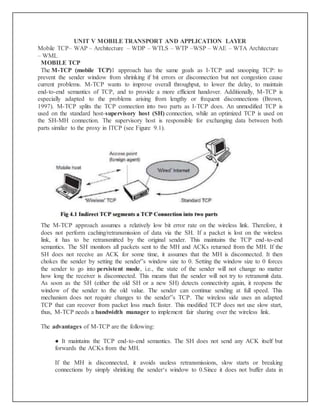
The M-TCP (mobile TCP)1 approach has the same goals as I-TCP and snooping TCP: to
prevent the sender window from shrinking if bit errors or disconnection but not congestion cause
current problems. M-TCP wants to improve overall throughput, to lower the delay, to maintain
end-to-end semantics of TCP, and to provide a more efficient handover. Additionally, M-TCP is
especially adapted to the problems arising from lengthy or frequent disconnections (Brown,
1997). M-TCP splits the TCP connection into two parts as I-TCP does. An unmodified TCP is
used on the standard host-supervisory host (SH) connection, while an optimized TCP is used on
the SH-MH connection. The supervisory host is responsible for exchanging data between both
parts similar to the proxy in ITCP (see Figure 9.1).
The M-TCP approach assumes a relatively low bit error rate on the wireless link. Therefore, it
does not perform caching/retransmission of data via the SH. If a packet is lost on the wireless
link, it has to be retransmitted by the original sender. This maintains the TCP end-to-end
semantics. The SH monitors all packets sent to the MH and ACKs returned from the MH. If the
SH does not receive an ACK for some time, it assumes that the MH is disconnected. It then
chokes the sender by setting the sender‟s window size to 0. Setting the window size to 0 forces
the sender to go into persistent mode, i.e., the state of the sender will not change no matter
how long the receiver is disconnected. This means that the sender will not try to retransmit data.
As soon as the SH (either the old SH or a new SH) detects connectivity again, it reopens the
window of the sender to the old value. The sender can continue sending at full speed. This
mechanism does not require changes to the sender‟s TCP. The wireless side uses an adapted
TCP that can recover from packet loss much faster. This modified TCP does not use slow start,
thus, M-TCP needs a bandwidth manager to implement fair sharing over the wireless link.
The advantages of M-TCP are the following:
● It maintains the TCP end-to-end semantics. The SH does not send any ACK itself but
forwards the ACKs from the MH.
If the MH is disconnected, it avoids useless retransmissions, slow starts or breaking
connections by simply shrinking the sender‘s window to 0.Since it does not buffer data in
2. the SH as I-TCP does, it is not necessary to forward buffers to a new SH. Lost packets
will be automatically retransmitted to the new SH.
The lack of buffers and changing TCP on the wireless part also has some disadvantages:
1 As the SH does not act as proxy as in I-TCP, packet loss on the wireless link due to bit
errors is propagated to the sender. M-TCP assumes low bit error rates, which is not always
a valid assumption.
2 A modified TCP on the wireless link not only requires modifications to the MH protocol
software but also new network elements like the bandwidth manager.
WIRELESS APPLICATION PROTOCOL
The growth of the internet, internet applications, and mobile
communications led to many early proprietary solutions providing internet services for mobile,
wireless devices. Some of the problems these partial solutions face were discussed in section
10.2 because the World Wide Web is the most important and fastest growing internet
application. To avoid many islands of incompatible solutions, e.g. special solutions for GSM,
IS-136, or certain manufacturers, the wireless application protocol forum (WAP Forum) was
founded in June 1997 by Ericsson, Motorola, Nokia, and Unwired Planet.
The basic objectives of the WAP Forum and now of the OMA are to bring diverse
internet content (e.g., web pages, push services) and other data services (e.g., stock quotes) to
digital cellular phones and other wireless, mobile terminals (e.g., PDAs, laptops). Moreover, a
protocol suite should enable global wireless communication across different wireless network
technologies, e.g., GSM, CDPD, UMTS etc. The forum is embracing and extending existing
standards and technologies of the internet wherever possible and is creating a framework for the
development of contents and applications that scale across a very wide range of wireless bearer
networks and wireless device types.
Interoperable, i.e., allowing terminals and software from different vendors to communicate
with networks from different providers;
Scalable, i.e., protocols and services should scale with customer needs and number of customers;
Efficient, i.e., provision of QoS suited to the characteristics of the wireless and mobile
networks;
WAP-ARCHITECTURE
3. The above Figure gives an overview of the WAP architecture, its protocols and
components, and compares this architecture with the typical internet architecture when using the
World Wide Web. This comparison is often cited by the WAP Forum and it helps to understand
the architecture (WAP Forum, 2000a). This comparison can be misleading as not all components
and protocols shown at the same layer are comparable. For consistency reasons with the existing
specification, the following stays with the model as shown in Figure 10.9.The basis for
transmission of data is formed by different bearer services. WAP does not specify bearer
services, but uses existing data services and will integrate further services. Examples are
message services, such as short message service (SMS) of GSM, circuit-switched data, such as
high-speed circuit switched data (HSCSD) in GSM, or packet switched data, such as general
packet radio service (GPRS) in GSM. Many other bearers are supported, such as CDPD, IS-136,
PHS. No special interface has been specified between the bearer service and the next higher
layer, the transport layer with its wireless datagram protocol (WDP) and the
additional wireless control message protocol (WCMP), because the adaptation of these
protocols are bearer-specific.
The transport layer offers a bearer independent, consistent datagram-oriented service to
the higher layers of the WAP architecture. Communication is done transparently over one of the
available bearer services. The transport layer service access point (T-SAP) is the common
interface to be used by higher layers independent of the underlying network. The next higher
layer, the security layer with its wireless transport layer security protocol WTLS offers its
service at the security SAP (SEC-SAP). WTLS is based on the transport layer security (TLS,
formerly SSL, secure sockets layer) already known from the www. WTLS has been optimized
for use in wireless networks with narrow-band channels. It can offer data integrity, privacy,
authentication, and (some) denial-of-service protection.
The WAP transaction layer with its wireless transaction protocol (WTP) offers a
lightweight transaction service at the transaction SAP (TR-SAP). This service efficiently
provides reliable or unreliable requests and asynchronous transactions as explained in the above
section. Tightly coupled to this layer is the next higher layer, if used for connection-oriented
service as described in section 10.3.5. The session layer with the wireless session
4. protocol (WSP) currently offers two services at the session-SAP (S-SAP), one connection-
oriented and one connectionless if used directly on top of WDP. A special service for browsing
the web (WSP/B) has been defined that offers HTTP/1.1 functionality, long-lived session state,
session suspend and resume, session migration and other features needed for wireless mobile
access to the web. Finally the application layer with the wireless application environment
(WAE) offers a framework for the integration of different www and mobile telephony
applications. It offers many protocols and services with special service access.
The main issues here are scripting languages, special markup languages, interfaces to
telephony applications, and many content formats adapted to the special requirements of small,
handheld, wireless devices. Figure 10.9 not only shows the overall WAP architecture, but also its
relation to the traditional internet architecture for www applications. The WAP transport layer
together with the bearers can be (roughly) compared to the services offered by TCP or UDP over
IP and different media in the internet. If a bearer in the WAP architecture already offers IP
services (e.g., GPRS, CDPD) then UDP is used as WDP. The TLS/SSL layer of the internet has
also been adopted for the WAP architecture with some changes required for optimization. The
functionality of the session and transaction layer can roughly be compared with the role of HTTP
in the web architecture. However, HTTP does not offer all the additional mechanisms needed for
efficient wireless, mobile access (e.g., session migration, suspend/resume).
Finally, the application layer offers similar features as HTML and Java. Again,
special formats and features optimized for the wireless scenario have been defined and telephony
access has been added.WAP does not always force all applications to use the whole protocol
architecture. Applications can use only a part of the architecture as shown in Figure 10.9. For
example, this means that, if an application does not require security but needs the reliable
transport of data, it can directly use a service of the transaction layer. Simple applications can
directly use WDP. Different scenarios are possible for the integration of WAP components into
existing wireless and fixed networks (see Figure 10.10). On the left side, different fixed
networks, such as the traditional internet and the public switched telephone network (PSTN), are
shown. One cannot change protocols and services of these existing networks so several new
elements will be implemented between these networks and the WAP-enabled wireless, mobile
devices in a wireless network on the right-hand side.
The current www in the internet offers web pages with the help of HTML and web
servers. To be able to browse these pages or additional pages with handheld devices, a wireless
markup language (WML) has been defined in WAP. Special filters within the fixed network can
now translate HTML into WML, web servers can already provide pages in WML, or the
gateways between the fixed and wireless network can translate HTML into WML. These
gateways not only filter pages but also act as proxies for web access, as explained in the
following sections.WML is additionally converted into binary WML for more efficient
transmission. In a similar way, a special gateway can be implemented to access traditional
telephone services via binary WML. This wireless telephony application (WTA) server
translates, e.g., signaling of the telephone network (incoming call etc.) into WML events
displayed at the handheld device. It is important to notice the integrated view for the wireless
client of all different services; telephony and web, via the WAE.
5. Wireless Datagram Protocol (WDP)
The Wireless Datagram Protocol (WDP) operates on top of many different bearer
services capable of carrying data. At the T-SAP WDP offers a consistent datagram transport
service independent of the underlying bearer. To offer this consistent service, the adaptation
needed in the transport layer can differ depending on the services of the bearer. The closer the
bearer service is to IP, the smaller the adaptation can be. If the bearer already offers IP services,
UDP is used as WDP. WDP offers more or less the same services as UDP. WDP
offers source and destination port numbers used for multiplexing and demultiplexing of data
respectively. The service primitive to send a datagram is TDUnitdata.req with the destination
address (DA), destination port (DP), Source address (SA), source port (SP), and user data
(UD) as mandatory parameters (see Figure 10.11). Destination and source address are unique
addresses for the receiver and sender of the user data. These could be MSISDNs (i.e., a telephone
number), IP addresses, or any other unique identifiers. The T-DUnitdata.ind service primitive
indicates the reception of data. Here destination address and port are only optional parameters.
If a higher layer requests a service the WDP cannot fulfill, this error is indicated with
the T-DError.ind service primitive as shown in Figure 10.11. An error code (EC) is returned
indicating the reason for the error to the higher layer. WDP is not allowed to use this primitive to
indicate problems with the bearer service. It is only allowed to use the primitive to indicate local
problems, such as a user data size that is too large. If any errors happen when WDP datagram‘s
are sent from one WDP entity to another (e.g. the destination is unreachable, no application is
listening to the specified destination port etc.), the wireless control message protocol
(WCMP) provides error handling mechanisms for WDP and should therefore be implemented.
WCMP contains control messages that resemble the internet control message protocol messages
and can also be used for diagnostic and informational purposes.
6. WCMP can be used by WDP nodes and gateways to report errors. However, WCMP
error messages must not be sent as response to other WCMP error messages. In IP-based
networks, ICMP will be used as WCMP (e.g., CDPD, GPRS). Typical WCMP messages
are destination unreachable (route, port, address unreachable), parameter problem (errors in
the packet header), message too big, reassembly failure, or echo request/reply. An additional
WDP management entity supports WDP and provides information about changes in
the environment, which may influence the correct operation of WDP. Important information is
the current configuration of the device, currently available bearer services, processing and
memory resources etc. Design and implementation of this management component is considered
vendor-specific and is outside the scope of WAP.
If the bearer already offers IP transmission, WDP (i.e., UDP in this case) relies on
the segmentation (called fragmentation in the IP context) and reassembly capabilities of the IP
layer as specified in (Postal, 1981a). Otherwise, WDP has to include these capabilities, which is,
e.g., necessary for the GSM SMS. The WAP specification provides many more adaptations to
almost all bearer services currently available or planned for the future (WAP Forum, 2000q),
(WAP Forum, 2000b).
Wireless Transport Layer Security (WTLS)
If requested by an application, a security service, the wireless transport layer
security (WTLS), can be integrated into the WAP architecture on top of WDP as specified in
(WAP Forum, 2000c). WTLS can provide different levels of security (for privacy, data integrity,
and authentication) and has been optimized for low bandwidth, high-delay bearer networks.
WTLS takes into account the low processing power and very limited memory capacity of the
mobile devices for cryptographic algorithms. WTLS supports datagram and connection-oriented
transport layer protocols. New compared to, e.g. GSM, is the security relation between two peers
and not only between the mobile device and the base station . WTLS took over many features
and mechanisms from TLS (formerly SSL, secure sockets layer, but it has an optimized
handshaking between the peers.
7. Before data can be exchanged via WTLS, a secure session has to be established. This
session establishment consists of several steps: Figure illustrates the sequence of service
primitives needed for a so-called ‗full handshake‘ (several optimizations are possible).
The originator and the peer of the secure session can both interrupt session establishment any
time, e.g., if the parameters proposed are not acceptable.
The first step is to initiate the session with the SEC-Create primitive. Parameters are
source address (SA), source port (SP) of the originator, destination address (DA), destination
port (DP) of the peer. The originator proposes a key exchange suite (KES) (e.g., RSA, DH, ECC,
a cipher suite (CS) (e.g., DES, IDEA, and a compression method (CM) (currently not further
specified). The peer answers with parameters for the sequence number mode (SNM), the key
refresh cycle (KR) (i.e., how often keys are refreshed within this secure session), the session
identifier (SID) (which is unique with each peer), and the selected key exchange suite (KES‘),
cipher suite (CS‘), compression method (CM‘). The peer also issues a SEC-Exchange primitive.
This indicates that the peer wishes to perform public-key authentication with the client, i.e., the
peer requests a client certificate (CC) from the originator.
The first step of the secure session creation, the negotiation of the security parameters
and suites, is indicated on the originator‘s side, followed by the request for a certificate. The
originator answers with its certificate and issues a SEC-Commit.req primitive. This primitive
indicates that the handshake is completed for the originator‘s side and that the originator now
wants to switch into the newly negotiated connection state. The certificate is delivered to the peer
side and the SEC-Commit is indicated. The WTLS layer of the peer sends back a confirmation to
the originator. This concludes the full handshake for secure session setup.
8. After setting up a secure connection between two peers, user data can be exchanged. This
is done using the simple SEC-Unit data primitive as shown in Figure 10.13. SEC-Unit data has
exactly the same function as T-D Unit data on the WDP layer, namely it transfers a datagram
between a sender and a receiver. This data transfer is still unreliable, but is now secure. This
shows that WTLS can be easily plugged into the protocol stack on top of WDP. The higher
layers simply use SEC-Unit data instead of T-D Unit data. The parameters are the same here:
source address (SA), source port (SP), destination address (DA), destination port (DP), and user
data (UD).
This section will not discuss the security-related features of WTLS or the pros and cons
of different encryption algorithms. The reader is referred to the specification and excellent
cryptography literature. Although WTLS allows for different encryption mechanisms with
different key lengths, it is quite clear that due to computing power on the handheld devices the
encryption provided cannot be very strong. If applications require stronger security, it is up to an
application or a user to apply stronger encryption on top of the whole protocol stack and use
WTLS as a basic security level only. Many programs are available for this purpose. It is
important to note that the security association in WTLS exists between the mobile WAP-enabled
devices and a WAP server or WAP gateway only. If an application accesses another server via
the gateway, additional mechanisms are needed for end-to-end security. If for example a user
accesses his or her bank account using WAP, the WTLS security association typically ends at the
WAP gateway inside the network operator‘s domain. The bank and user will want to apply
additional security mechanisms in this scenario.
Future work in the WTLS layer comprises consistent support for application level
security (e.g. digital signatures) and different implementation classes with different capabilities
to select from.
Wireless transaction protocol (WTP)
The wireless transaction protocol (WTP) is on top of either WDP or, if security is
required, WTLS (WAP Forum, 2000d). WTP has been designed to run on very thin clients, such
as mobile phones. WTP offers several advantages to higher layers, including an improved
reliability over datagram services, improved efficiency over connection-oriented services, and
support for transaction-oriented services such as web browsing. In this context, a transaction is
defined as a request with its response, e.g. for a web page. WTP offers many features to the
9. higher layers. The basis is formed from three classes of transaction service as explained in the
following paragraphs. Class 0 provides unreliable message transfer without any result message.
Classes 1 and 2 provide reliable message transfer, class 1 without, class 2 with, exactly one
reliable result message (the typical request/response case).
WTP achieves reliability using duplicate removal, retransmission, acknowledgements and
unique transaction identifiers. No WTP-class requires any connection set-up or tear-down phase.
This avoids unnecessary overhead on the communication link. WTP allows for asynchronous
transactions, abort of transactions, concatenation of messages, and can report success or failure
of reliable messages (e.g., a server cannot handle the request). To be consistent with the
specification, in the following the term initiator is used for a WTP entity initiating a transaction
(aka client), and the term responder for the WTP entity responding to a transaction (aka server).
The three service primitives offered by WTP are TR-Invoke to initiate a new transaction, TR-
Result to send back the result of a previously initiated transaction, and TR-Abort to abort an
existing transaction. The PDUs exchanged between two WTP entities for normal transactions are
the invoke PDU, ack PDU, and result PDU.
A special feature of WTP is its ability to provide a user acknowledgement or,
alternatively, an automatic acknowledgement by the WTP entity. If user acknowledgement is
required, a WTP user has to confirm every message received by a WTP entity. A user
acknowledgement provides a stronger version of a confirmed service because it guarantees that
the response comes from the user of the WTP and not the WTP entity itself. WTP class 0 Class 0
offers an unreliable transaction service without a result message. The transaction is stateless and
cannot be aborted. The service is requested with the TR-Invoke.req primitive as shown in Figure
10.14. Parameters are the source address (SA), source port (SP), destination address (DA),
destination port (DP) as already explained in section 10.3.2. Additionally, with the A flag the
user of this service can determine, if the responder WTP entity should generate an
acknowledgement or if a user acknowledgement should be used. The WTP layer will transmit
the user data (UD) transparently to its destination. The class type C indicates here class 0.
Finally, the transaction handle H provides a simple index to uniquely identify the transaction and
is an alias for the tuple (SA, SP, DA, DP), i.e., a socket pair, with only local significance.
The WTP entity at the initiator sends an invoke PDU which the responder receives. The
WTP entity at the responder then generates a TR-Invoke.ind primitive with the same parameters
as on the initiators side, except for which is now the local handle for the transaction on the
responders side. In this class, the responder does not acknowledge the message and the initiator
10. does not perform any retransmission. Although this resembles a simple datagram service, it is
recommended to use WDP if only a datagram service is required. WTP class 0 augments the
transaction service with a simple datagram like service for occasional use by higher layers.
WTP class 1 Class 1 offers a reliable transaction service but without a result message.
Again, the initiator sends an invoke PDU after a TR-Invoke.req from a higher layer.
This time, class equals „1, and no user acknowledgement has been selected as shown in
Figure 10.15. The responder signals the incoming invoke PDU via the TR-Invoke.ind primitive
to the higher layer and acknowledges automatically without user intervention. The specification
also allows the user on the responders side to acknowledge, but this acknowledgement is not
required. For the initiator the transaction ends with the reception of the acknowledgement. The
responder keeps the transaction state for some time to be able to retransmit the acknowledgement
if it receives the same invoke PDU again indicating a loss of the acknowledgement.
If a user of the WTP class 1 service on the initiators side requests a user
acknowledgement on the responders side, the sequence diagram looks like Figure. Now the WTP
entity on the responders side does not send an acknowledgement automatically, but waits for the
TR-Invoke.res service primitive from the user. This service primitive must have the appropriate
local handle H for identification of the right transaction. The WTP entity can now send the ack
PDU. Typical uses for this transaction class are reliable push services.
WTP class 2 Finally, class 2 transaction service provides the classic
reliable request/response transaction known from many client/server scenarios. Depending on
user requirements, many different scenarios are possible for initiator/responder interaction. Three
examples are presented below. Figure shows the basic transaction of class 2 without-user
acknowledgement. Here, a user on the initiators side requests the service and the WTP entity
sends the invoke PDU to the responder. The WTP entity on the responders side indicates the
request with the TR-Invoke.ind primitive to a user. The responder now waits for the processing
of the request, the user on the responders side can finally give the result UD* to the WTP entity
on the responder side using TR-Result.req. The result PDU can now be sent back to the initiator,
which implicitly acknowledges the invoke PDU. The initiator can indicate the successful
transmission of the invoke message and the result with the two service primitives TR-Invoke.cnf
and TR-Result.ind. A user may respond to this result with TR-Result.res. An acknowledgement
PDU is then generated which finally triggers the TR-Result.cnf primitive on the responder‟s
11. side. This example clearly shows the combination of two reliable services (TR-Invoke and TR-
Result) with an efficient data transmission/acknowledgement.
An even more reliable service can be provided by user acknowledgement as explained
above. The time-sequence diagram looks different (see Figure 10.18). The user on the
responder‘s side now explicitly responds to the Invoke PDU using the TR-Invoke.res primitive,
which triggers the TR-Invoke.cnf on the initiator‘s side via an ack PDU. The transmission of the
result is also a confirmed service, as indicated by the next four service primitives. This service
will likely be the most common in standard request/response scenarios as, e.g., distributed
computing.
12. If the calculation of the result takes some time, the responder can put the initiator on
―hold on‖ to prevent a retransmission of the invoke PDU as the initiator might assume packet
loss if no result is sent back within a certain timeframe. This is shown in the Figure.
After a time-out, the responder automatically generates an acknowledgement for the
Invoke PDU. This shows the initiator that the responder is still alive and currently busy
processing the request. WTP provides many more features not explained here, such as
concatenation and separation of messages, asynchronous transactions with up to 215 transactions
outstanding, i.e., requested but without result up to now, and segmentation/ reassembly of
messages.
Wireless session protocol (WSP)
The wireless session protocol (WSP) has been designed to operate on top of the
datagram service WDP or the transaction service WTP (WAP Forum, 2000e). For both types,
security can be inserted using the WTLS security layer if required. WSP provides a shared state
between a client and a server to optimize content transfer. HTTP, a protocol WSP tries to replace
within the wireless domain, is stateless, which already causes many problems in fixed networks.
Many web content providers therefore use cookies to store some state on a client machine, which
is not an elegant solution. State is needed in web browsing, for example, to resume browsing in
exactly the same context in which browsing has been suspended. This is an important feature for
clients and servers. Client users can continue to work where they left the browser or when the
network was interrupted, or users can get their customized environment every time they start the
browser. Content providers can customize their pages to clients‘ needs and do not have to
retransmit the same pages over and over again. WSP offers the following general features needed
for content exchange between cooperating clients and servers:
● Session management: WSP introduces sessions that can be established from a client to a
server and may be long lived. Sessions can also be released in an orderly manner. The
13. capabilities of suspending and resuming a session are important to mobile applications. Assume
a mobile device is being switched off – it would be useful for a user to be able to continue
operation at exactly the point where the device was switched off. Session lifetime is independent
of transport connection lifetime or continuous operation of a bearer network.
Capability negotiation: Clients and servers can agree upon a common level of
protocol functionality during session establishment. Example parameters to negotiate are
maximum client SDU size, maximum outstanding requests, protocol options, and server SDU
size.
Content encoding: WSP also defines the efficient binary encoding for the content it transfers.
WSP offers content typing and composite objects, as explained for web browsing. While WSP is
a general-purpose session protocol, WAP has specified the wireless session
protocol/browsing (WSP/B) which comprises protocols and services most suited for browsing-
type applications. In addition to the general features of WSP, WSP/B offers the following
features adapted to web browsing:
d) HTTP/1.1 functionality: WSP/B supports the functions HTTP/1.1 offers, such as extensible
request/reply methods, composite objects, and content type negotiation. WSP/B is a binary form
of HTTP/1.1. HTTP/1.1 content headers are used to define content type, character set encoding,
languages etc., but binary encodings are defined for well-known headers to reduce protocol
overheads.
e) Exchange of session headers: Client and server can exchange request/reply headers that
remain constant over the lifetime of the session. These headers may include content types,
character sets, languages, device capabilities, and other static parameters. WSP/B will not
interpret header information
but passes all headers directly to service users.
f) Push and pull data transfer: Pulling data from a server is the traditional mechanism of
the web. This is also supported by WSP/B using the request/response mechanism from
HTTP/1.1. Additionally, WSP/B supports three push mechanisms for data transfer: a confirmed
data push within an existing session context, a non-confirmed data push within an existing
session context, and a non-confirmed data push without an existing session context.
g) Asynchronous requests: Optionally, WSP/B supports a client that can send multiple
requests to a server simultaneously. This improves efficiency for the requests and replies can
now be coalesced into fewer messages. Latency is also improved, as each result can be sent to
the client as soon as it is available.
As already mentioned, WSP/B can run over the transaction service WTP or the datagram service
WDP. The following shows several protocol sequences typical for session management, method
invocation, and push services.
Wireless Application Environment
14. The main idea behind the wireless application environment (WAE) is to create a general-
purpose application environment based mainly on existing technologies and philosophies of the
world wide web. This environment should allow service providers, software manufacturers, or
hardware vendors to integrate their applications so they can reach a wide variety of different
wireless platforms in an efficient way. However, WAE does not dictate or assume any specific
man-machine-interface model, but allows for a variety of devices, each with its own capabilities
and probably vendor-specific extras (i.e., each vendor can have its own look and feel). WAE has
already integrated the following technologies and adapted them for use in a wireless environment
with low power handheld devices.
HTML, JavaScript, and the handheld device markup language HDML form the basis of
the wireless markup language (WML) and the scripting language WML script. The exchange
formats for business cards and phone books vCard and for calendars vCalendar have been
included. URLs from the web can be used. A wide range of mobile telecommunication
technologies have been adopted and integrated into the wireless telephony application (WTA).
Besides relying on mature and established technology, WAE focuses on devices with
very limited capabilities, narrow-band environments, and special security and access control
features. The first phase of the WAE specification developed a whole application suite,
especially for wireless clients as presented in the following sections. Future developments for the
WAE will include extensions for more content formats, integration of further existing or
emerging technologies, more server-side aspects, and the integration of intelligent telephone
networks.
One global goal of the WAE is to minimize over-the-air traffic and resource consumption
on the handheld device. This goal is also reflected in the logical model underlying WAE (Figure
10.29) showing some more detail than the general overview in Figure 10.10. WAE adopts a
model that closely follows the www model, but assumes additional gateways that can enhance
transmission efficiency.
A client issues an encoded request for an operation on a remote server. Encoding is
necessary to minimize data sent over the air and to save resources on the handheld device as
explained together with the languages WML and WMLscript. Decoders in a gateway now
translate this encoded request into a standard request as understood by the origin servers. This
could be a request to get a web page to set up a call. The gateway transfers this request to the
15. appropriate origin server as if it came from a standard client. Origin servers could be standard
web servers running HTTP and generating content using scripts, providing pages using a
database, or applying any other (proprietary) technology. WAE does not specify any standard
content generator or server, but assumes that the majority will follow the standard technology
used in today‘s www.
The origin servers will respond to the request. The gateway now encodes the response
and its content (if there is any) and transfers the encoded response with the content to the client.
The WAE logical model not only includes this standard request/response scheme, but it also
includes push services. Then an origin server pushes content to the gateway. The gateway
encodes the pushed content and transmits the encoded push content to the client.
Several user agents can reside within a client. User agents include such items as:
browsers, phonebooks, message editors etc. WAE does not specify the number of user agents or
their functionality, but assumes a basic WML user agent that supports WML, WML script, or
both (i.e., a ‗WML browser‘). Further domain specific user agents with varying architectures can
be implemented. Again, this is left to vendors. However, one more user agent has been specified
with its fundamental services, the WTA user agent. This user agent handles access to, and
interaction with, mobile telephone features (such as call control). As over time many vendor
dependent user agents may develop, the standard defines a user agent profile (UAProf), which
describes the capabilities of a user agent. Capabilities may be related to hardware or software.
Examples are: display size, operating system, browser version, processor, memory size,
audio/video codec, or supported network types. The basic languages WML and WML Script ,
and the WTA will be described in the following three sections.
WTA Architecture
Browsing the web using the WML browser is only one application for a handheld
device user. Say a user still wants to make phone calls and access all the features of the mobile
phone network as with a traditional mobile phone. This is where the wireless telephony
application (WTA), the WTA user agent (as shown in Figure), and the wireless telephony
application interface WTAI come in. WTA is a collection of telephony specific extensions for
call and feature control mechanisms, merging data networks and voice networks.
The WTA framework integrates advanced telephony services using a consistent user
interface (e.g., the WML browser) and allows network operators to increase accessibility for
various special services in their network. A network operator can reach more end-devices using
WTA because this is integrated in the wireless application environment (WAE) which handles
device-specific characteristics and environments. WTA should enable third-party developers as
well as network operators to create network-independent content that accesses the basic features
of the bearer network. However, most of the WTA functionality is reserved for the network
operators for security and stability reasons.
WTA extends the basic WAE application model in several ways:
16. ● Content push: A WTA origin server can push content, i.e., WML decks or WMLScript, to
the client. A push can take place without prior client request. The content can enable, e.g., the
client to handle new network events that were unknown before.
● Access to telephony functions: The wireless telephony application interface (WTAI,
WAP Forum, 2000m) provides many functions to handle telephony events (call accept, call
setup, change of phone book entries etc.).
● Repository for event handlers: The repository represents a persistent storage on the client
for content required to offer WTA services. Content are either channels or resources. Examples
for resources are WML decks, WMLScript objects, or WBMP pictures. Resources are loaded
using WSP or are pre-installed. A channel comprises references to resources and is associated
with a lifetime. Within this lifetime, it is guaranteed that all resources the channel points to are
locally available in the repository. The motivation behind the repository is the necessity to react
very quickly for time-critical events (e.g., call accept). It would take too long to load content
from a server for this purpose.
● Security model: Mandatory for WTA is a security model as many frauds happen with
wrong phone numbers or faked services. WTA allows the client to only connect to trustworthy
gateways, which then have to check if the servers providing content are authorized to send this
content to the client. Obviously, it is not easy to define trustworthy in this context. In the
beginning, the network operator‟s gateway may be the only trusted gateway and the network
operator may decide which servers are allowed to provide content. Figure 10.30 gives an
overview of the WTA logical architecture.
The components shown are not all mandatory in this architecture; however, firewalls or
other origin servers may be useful. A minimal configuration could be a single server from the
network operator serving all clients. The client is connected via a mobile network with
a WTA server, other telephone networks (e.g., fixed PSTN), and a WAP gateway. A WML
user agent running on the client or on other user agents is not shown here.
17. The client may have voice and data connections over the mobile network. Other
origin servers within the trusted domain may be connected via the WAP gateway. A firewall is
useful to connect third-party origin servers outside the trusted domain. One difference between
WTA servers and other servers besides security is the tighter control of QoS. A network operator
knows (more or less precisely) the latency, reliability, and capacity of its mobile network and can
have more control over the behavior of the services. Other servers, probably located in the
internet, may not be able to give as good QoS guarantees as the network operator.
Similarly, the WTA user agent has a very rigid and real-time context management
for browsing the web compared to the standard WML user agent. Figure shows an exemplary
interaction between a WTA client, a WTA gateway, a WTA server, the mobile network (with
probably many more servers) and a voice box server. Someone might leave a message on a voice
box server as indicated. Without WAP, the network operator then typically generates an SMS
indicating the new message on the voice box via a little symbol on the mobile phone. However,
it is typically not indicated who left a message, what messages are stored etc. Users have to call
the voice box to check and cannot choose a particular message. In a WAP scenario, the voice
box can induce the WTA server to generate new content for pushing to the client. An example
could be a WML deck containing a list of callers plus length and priority of the calls. The server
does not push this deck immediately to the client, but sends a push message containing a single
URL to the client. A short note, e.g., ―5 new calls are stored", could accompany the
push message. The WTA gateway translates the push URL into a service indication and codes it
into a more compact binary format. The WTA user agent then indicates that new messages are
stored. If the user wants to listen to the stored messages, he or she can request a list of the
messages.
This is done with the help of the URL. A WSP get requests the content the URL points to. The
gateway translates this WSP get into an HTTP get and the server responds with the prepared list
of callers.
18. After displaying the content, the user can select a voice message from the list. Each voice
message in this example has an associated URL, which can request a certain WML card from the
server. The purpose of this card is to prepare the client for an incoming call. As soon as the client
receives the card, it waits for the incoming call. The call is then automatically accepted. The
WTA server also signals the voice box system to set up a (traditional) voice connection to play
the selected voice message. Setting up the call and accepting the call is shown using dashed
lines, as these are standard interactions from the mobile phone network, which are not controlled
by WAP.
Wireless markup language (WML)
The wireless markup language (WML) (WAP Forum, 2000j) is based on the standard
HTML known from the www and on HDML (King, 1997). WML is specified as an XML (W3C,
1998a) document type. When designing WML, several constraints of wireless handheld devices
had to be taken into account. First of all, the wireless link will always have only a very limited
capacity compared to a wire. Current handheld devices have small displays, limited user input
facilities, limited memory, and only low performance computational resources. While the
bandwidth argument will remain for many years, it currently seems that the gap between mobile
and fixed devices regarding processing power is getting narrower.
Today‘s CPUs in PDAs have performance figures close to desktop CPUs just a few
years ago. WML follows a deck and card metaphor. A WML document is made up of
multiple cards. Cards can be grouped together into a deck. A WML deck is similar to an HTML
19. page, in that it is identified by a URL and is the unit of content transmission. A user navigates
with the WML browser through a series of WML cards, reviews the contents, enters requested
data, makes choices etc. The WML browser fetches decks as required from origin servers. Either
these decks can be static files on the server or they can be dynamically generated.
It is important to note that WML does not specify how the implementation of a WML
browser has to interact with a user. Instead, WML describes the intent of interaction in an
abstract manner. The user agent on a handheld device has to decide how to best present all
elements of a card. This presentation depends much on the capabilities of the device.
WML includes several basic features:
● Text and images: WML gives, as do other mark-up languages, hints how text and images
can be presented to a user. However, the exact presentation of data to a user is up to the user
agent running on the handheld device. WML only provides a set of mark-up elements, such as
emphasis elements (bold, italic, etc.) for text, or tab columns for tabbing alignment.
● User interaction: WML supports different elements for user input. Examples are: text
entry controls for text or password entry, option selections or controls for task invocation. Again,
the user agent is free to choose how these inputs are implemented. They could be bound to, e.g.,
physical keys, soft keys, or voice input.
Navigation: As with HTML browsers, WML offers a history mechanism with
navigation through the browsing history, hyperlinks and other inter card navigation elements.
● Context management: WML allows for saving the state between different decks without
server interaction, i.e., variable state can last longer than a single deck, and so state can be shared
across different decks. Cards can have parameters defined by using this state without access to
the server over the narrow-band wireless channel.
The following paragraph gives a simple example of WML; the reader is referred to the
standard or Singhal (2001) for a full reference and in-depth discussion of the language.
First, a reference to XML is given where WML was derived from. Then, after the keyword wml
the first card is defined. This first card of the deck ―displays‖ a text after loading (―displaying‖
could also mean voice output etc.). As soon as a user activates the do element (a button or voice
command), the user agent displays the second card. On this second card, the user can select one
out of three pizza options. Depending on the choice of the user, PIZZA can have one of the
values Mar, Fun, or Vul. If the user proceeds to the third card without choosing a pizza, the value
Mar is used as default. Again, describing these options with WML does not automatically mean
that these options are displayed as text. It could also be possible that the user agent reads the
options through a voice output and the user answers through a voice input. WML only describes
the intention of a choice. The third card finally outputs the value of PIZZA.
<?xml version="1.0"?>
20. <!DOCTYPE wml PUBLIC "-//WAPFORUM//DTD WML 1.1//EN"
"http://www.wapforum.org/DTD/wml_1.1.xml">
<wml>
<card id="card_one" title="Simple example"> <do type="accept">
<go href="#card_two"/> </do>
<p>
This is a simple first card! <br/>
On the next one you can choose ...
</p>
</card>
<card id="card_two" title="Pizza selection"> <do type="accept" label="cont">
<go href="#card_three"/> </do>
<p>
... your favourite pizza!
<select value="Mar" name="PIZZA"> <option value="Mar">Margherita</option> <option
value="Fun">Funghi</option> <option value="Vul">Vulcano</option> </select>
</p>
</card>
<card id="card_three" title="Your Pizza!"> <p>
Your personal pizza parameter is <b>$(PIZZA)</b>! </p>
</card>
</wml>
WML may be encoded using a compact binary representation to save bandwidth on the wireless
link. This compact representation is based on the binary XML content format as specified in
WAP Forum (2000k). The binary coding of WML is only one special version of this format; the
compact representation is valid in general for XML content. The compact format allows for
transmission without loss of functionality or of semantic information. For example, the URL
prefix href=_http://, which is very common in URLs, will be coded as 4B. The code for the select
keyword is 37 and option is 35. These single byte codes are much more efficient than the plain
ASCII text used in HTML and today‘s www.