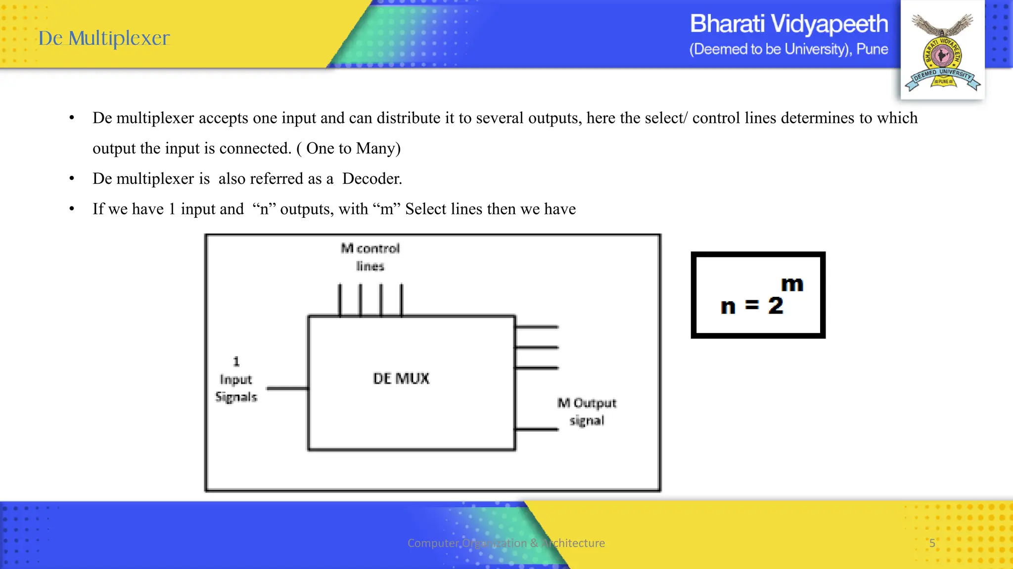
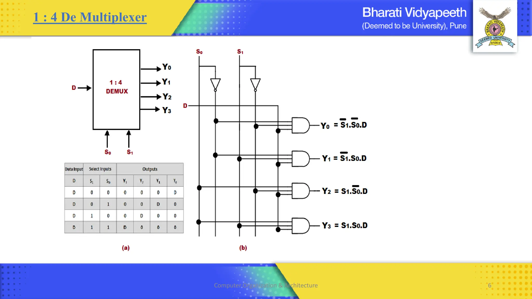
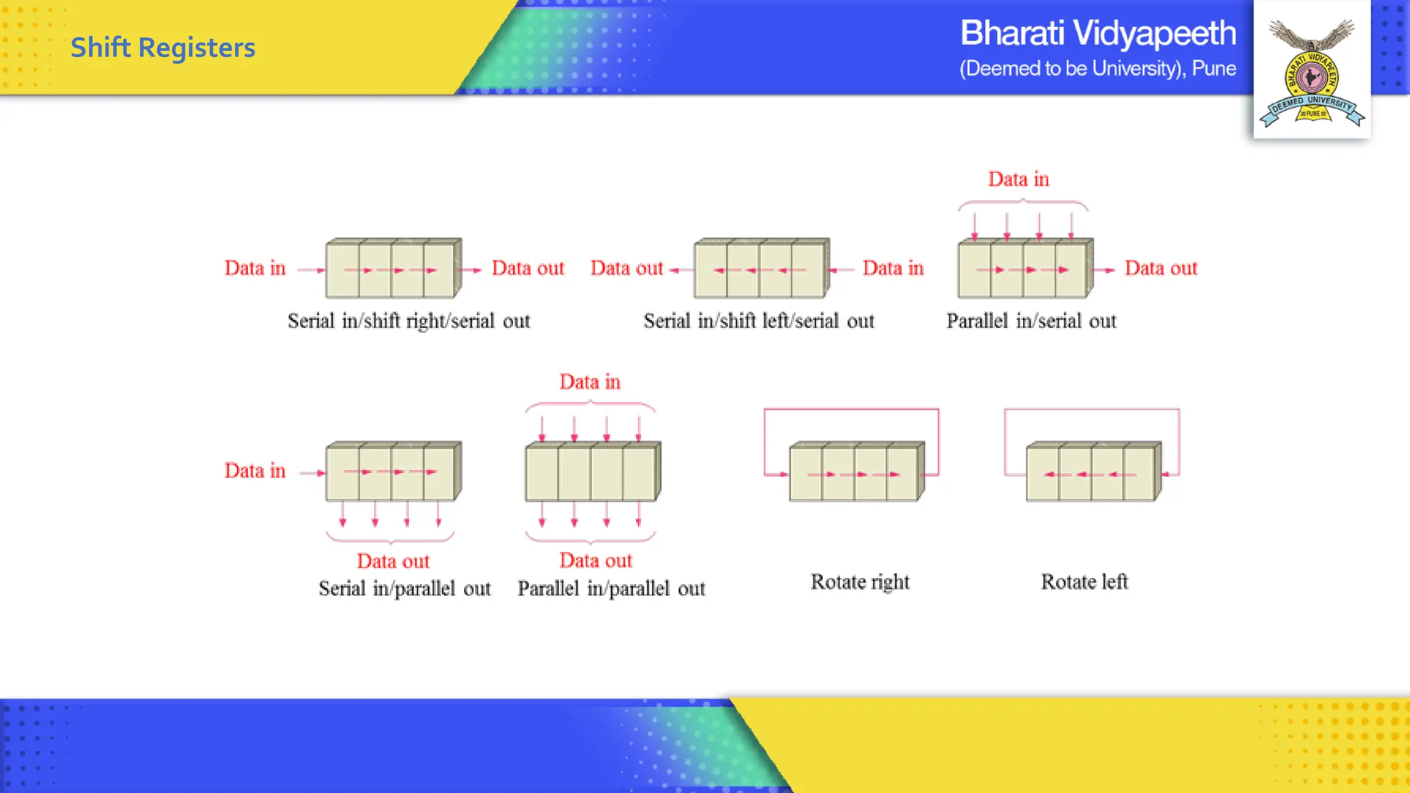
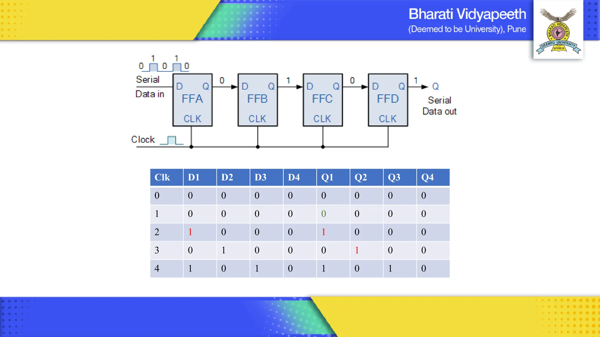
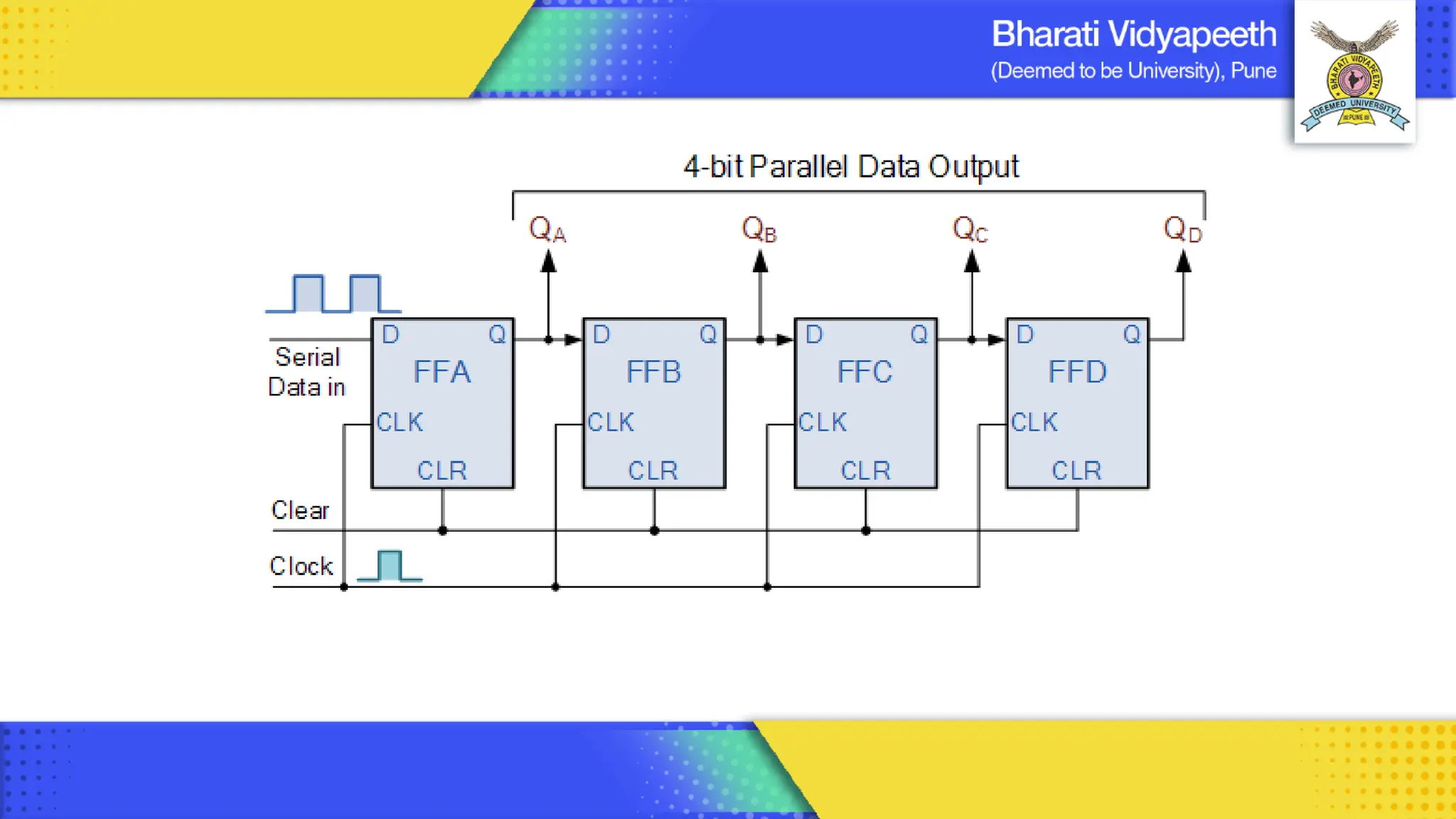
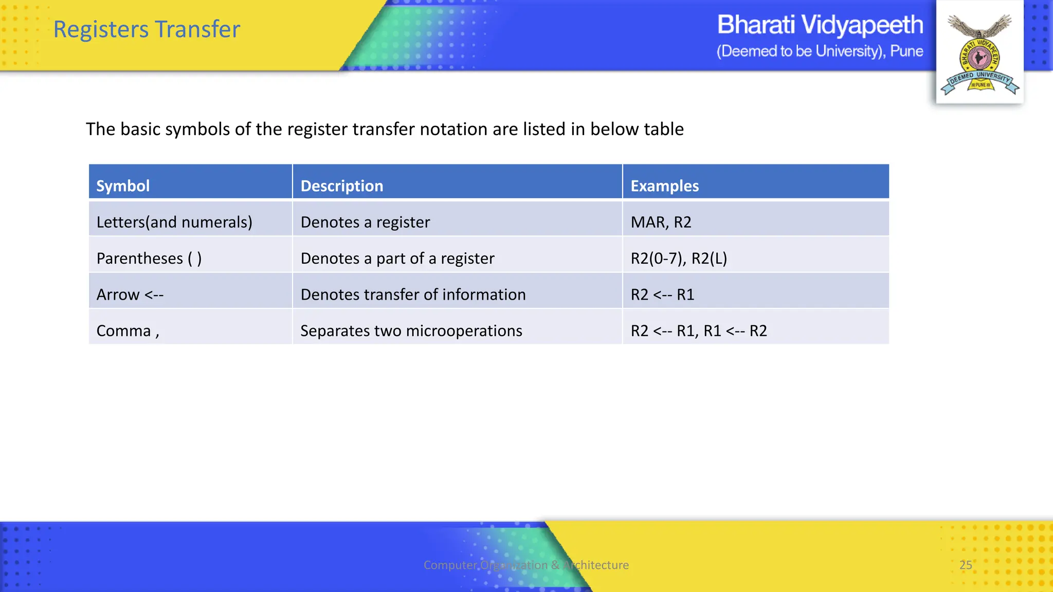
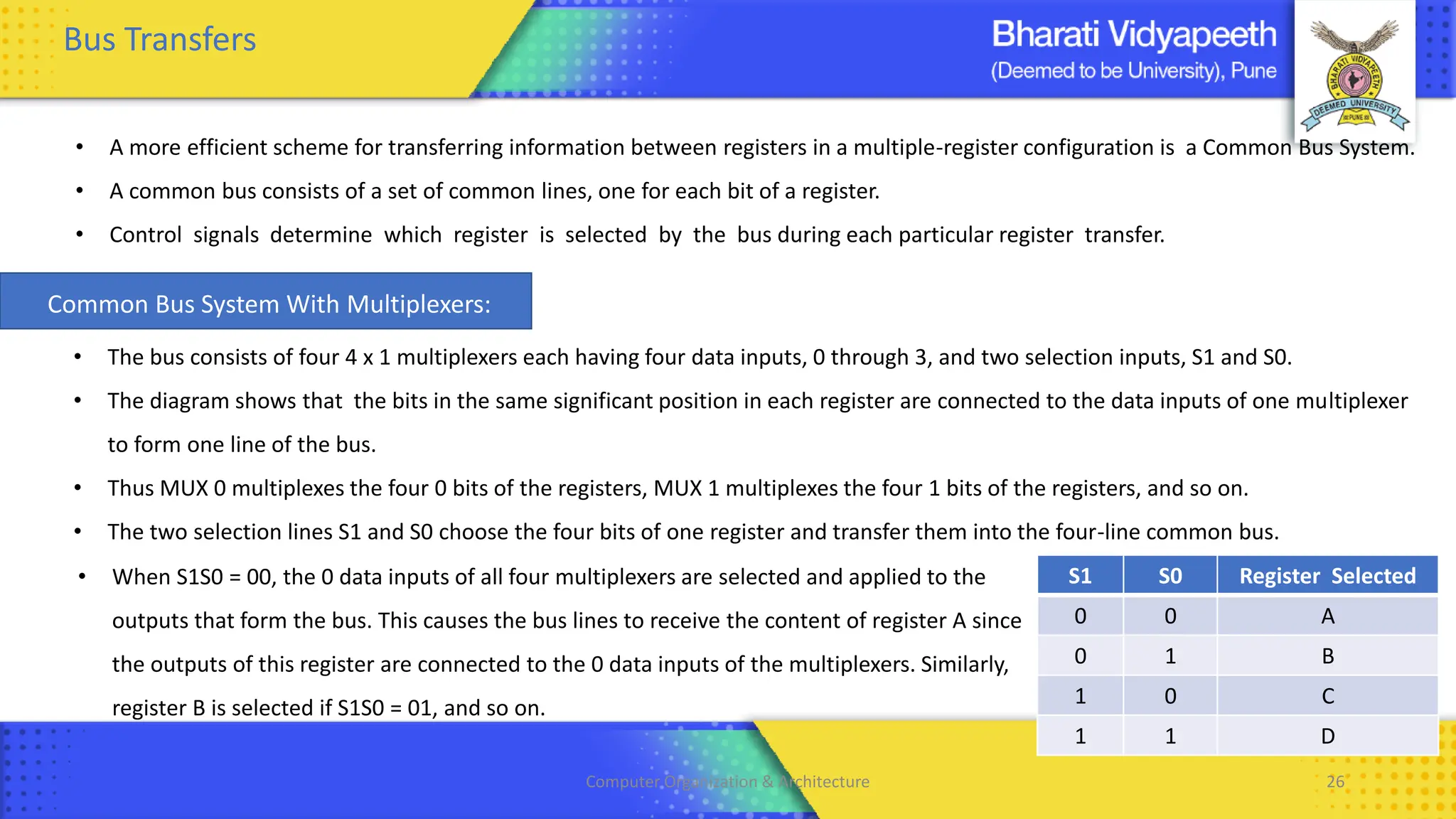
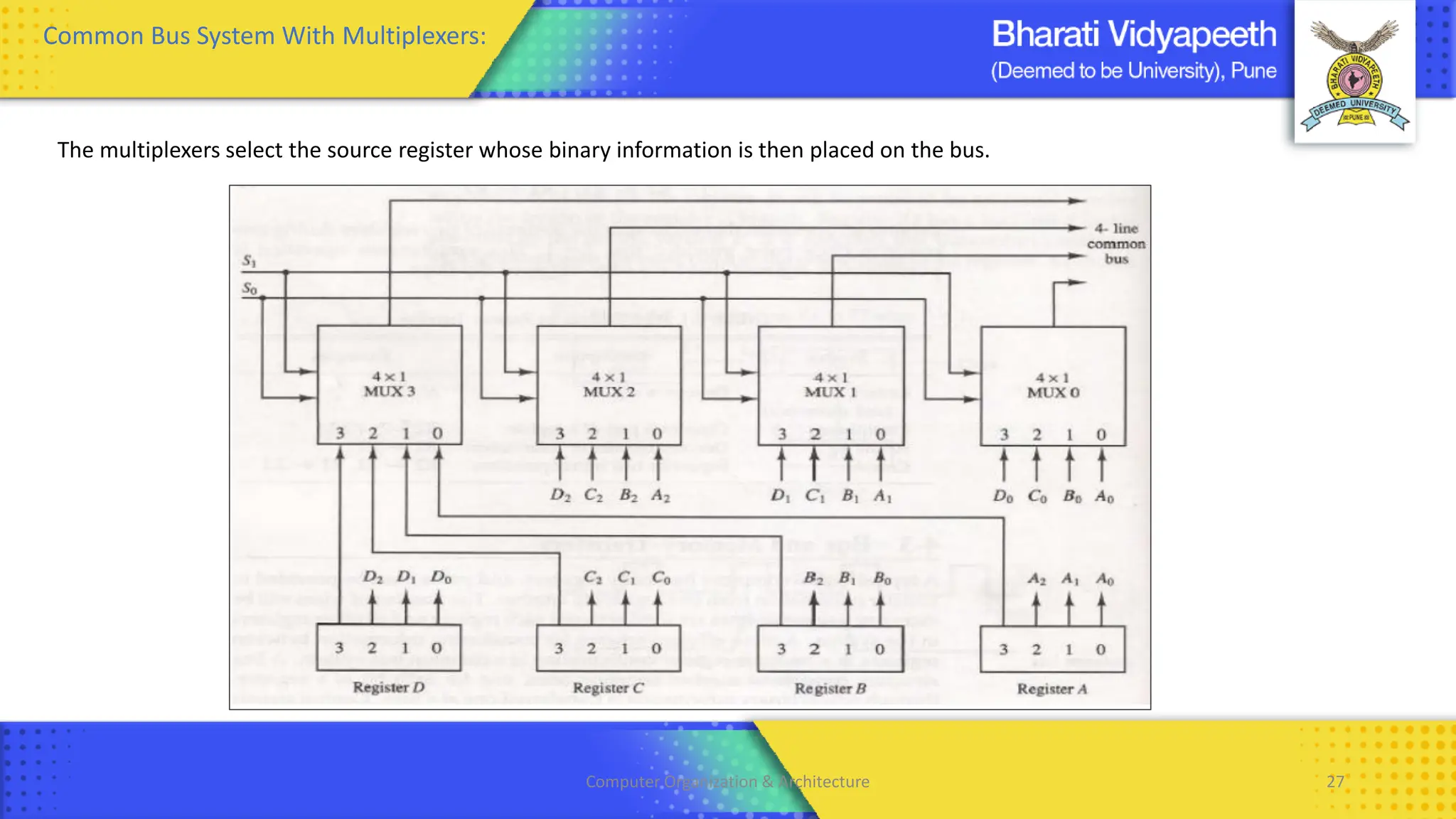
Computer Organization & Architecture
Introduction to Digital Components & Micro Operations
Chapter 2
BCA , Sem - II
1
• The Multiplexer acts as a multiple-input and single-output switch.
• Multiple signals share one device or transmission line
• In telecommunications, the analog or digital signals transmitted on several communication channels by a multiplex method.
Computer Organization & Architecture 2
2 : 1 Multiplexer
S’ D0
S D0 D1 Y
0 0 X 0
0 1 X 1
1 X 0 0
1 X 1 1 S D1
Computer Organization & Architecture 3
4 : 1 Multiplexer
Computer Organization & Architecture 4
• De multiplexer accepts one input and can distribute it to several outputs, here the select/ control lines determines to which
output the input is connected. ( One to Many)
• De multiplexer is also referred as a Decoder.
• If we have 1 input and “n” outputs, with “m” Select lines then we have
Computer Organization & Architecture 5
1 : 4 De Multiplexer
Computer Organization & Architecture 6
Decimal Binary BCD HEX
0 0000 0000 0
1 0001 0001 1
2 0010 0010 2
3 0011 0011 3
4 0100 0100 4
5 0101 0101 5
6 0110 0110 6
7 0111 0111 7
Binary Coded Decimal
210 : 0010 0001 0000
Computer Organization & Architecture
7
Decimal Binary BCD HEX
8 1000 1000 8
9 1001 1001 9
10 1010 0001 0000 A
11 1011 0001 0001 B
12 1100 0001 0010 C
13 1101 0001 0011 D
14 1110 0001 0100 E
15 1111 0001 0101 F
Computer Organization & Architecture 8
Decimal Input A B C D
0 0 0 0 0
1 0 0 0 1
2 0 0 1 0
3 0 0 1 1
4 0 1 0 0
5 0 1 0 1
6 0 1 1 0
7 0 1 1 1
8 1 0 0 0
9 1 0 0 1
A = 8+9
B = 4+5+6+7
C = 2+3+6+7
D = 1+3+5+7+9
DecimalTo BCD Encoder
Computer Organization & Architecture 9
Definition : It is a combinational logic circuit that converts encoded signal back to its original form.
It accepts coded inputs and generates the desired standard output.
Computer Organization & Architecture 10
BCD To Decimal Decoder
A B C D Output
0 0 0 0 Y0
0 0 0 1 Y1
0 0 1 0 Y2
0 0 1 1 Y3
0 1 0 0 Y4
0 1 0 1 Y5
0 1 1 0 Y6
0 1 1 1 Y7
1 0 0 0 Y8
1 0 0 1 Y9
A’B’C’D
AB’C’D’
A’B’CD’
A’B’CD
A’BC’D’
A’BC’D
A’BCD’
A’BCD
A’B’C’D’
AB’C’D
Computer Organization & Architecture 11
Shift Registers
1) Serial In Serial Out ( SISO) : 8 Clk
2) Serial In Parallel Out ( SIPO) : 5 Clk
3) Parallel In Serial Out ( PISO) : 5 Clk
4) Parallel In Parallel Out ( PIPO) : 2 Clk
• A Register is a group of Flip-flops used to store or rotate the binary data.
• The shift Register rotates the bits for certain Arithmetic operations.
• Shift Left or Shift Right ( Serial and Parallel shift)
• Generally , D Flip flops are used to built Shift Registers.
Applications:
• Temporary Data Storage in a Microprocessor.
• Data shifting or for data rotate applications
• Data conversions like Serial to Parallel and vice a versa
• For delay generation in data transmission.
Shift Registers
Clk D1 D2 D3 D4 Q1 Q2 Q3 Q4
0 0 0 0 0 0 0 0 0
1 0 0 0 0 0 0 0 0
2 1 0 0 0 1 0 0 0
3 0 1 0 0 0 1 0 0
4 1 0 1 0 1 0 1 0
Computer Organization & Architecture 16
Computer Organization & Architecture 18
Computer Organization & Architecture 19
Computer Organization & Architecture 20
Clk QC QB QA No of state
Initial 0 0 0 1
1 0 0 1 2
2 0 1 0 3
3 0 1 1 4
4 1 0 0 5
5 1 0 1 6
6 1 1 0 7
7 1 1 1 8
8 0 0 0
Negative edge triggered : value changes from 1 to 0
Computer Organization & Architecture 21
Register Transfer And Microoperation
• A digital system is an interconnection of digital hardware modules.
• The modules are registers, decoders, arithmetic elements, and control logic.
• The various modules are interconnected with common data and control paths to form a digital computer system.
• The operations executed on data stored in registers are called MICROOPERATIONS.
• A microoperation is an elementary operation performed on the information stored in one or more registers.
• The result of the operation may replace the previous binary information of a register or may be transferred to
another register.
• Examples of microoperations are shift, count, clear, and load.
• The internal hardware organization of a digital computer is best defined by specifying:
1. The set of registers it contains and their function.
2. The sequence of microoperations performed on the binary information stored in the registers.
3. The control that initiates the sequence of microoperations.
Computer Organization & Architecture 22
Register Transfer Language
• The symbolic notation used to describe the micro-operation transfer among registers is called RTL
(REGISTER TRANSFER LANGUAGE).
• The use of symbols instead of a narrative explanation provides an organized manner for listing the micro-operation.
• It is a convenient tool for describing the internal organization of digital computers in precise manner
Registers
• Computer registers are designated by upper case letters (and optionally followed by digits or letters) to denote the
function of the register.
• For example, the register that holds an address for the memory unit is usually called a MEMORY ADDRESS REGISTER and
is designated by the name MAR.
• Other designations for registers are PC (for program counter), IR (for instruction register, and R1 (for processor register).
The individual flip-flops in an n-bit register are numbered in sequence from 0 through n-1, starting from 0 in the rightmost
position and increasing the numbers toward the left.
Computer Organization & Architecture 23
Registers
• The most common way to represent a register is by a rectangular box with the name of the register inside,
• The individual bits can be distinguished as in (b).
• The numbering of bits in a 16-bit register can be marked on top of the box as shown in (c).
• 16-bit register is partitioned into two parts in (d). Bits 0 through 7 are assigned the symbol L (for low byte) and bits 8
through 15 are assigned the symbol H (for high byte).
• The name of the 16-bit register is PC. The symbol PC (0-7) or PC (L) refers to the low-order byte and PC (8-15) or PC (H)
to the high-order byte
Computer Organization & Architecture 24
Registers Transfer
• Information transfer from one register to another is designated in symbolic form by means of a replacement operator.
• The statement R2← R1 denotes a transfer of the content of register R1 into register R2.
• It designates a replacement of the content of R2 by the content of R1.
• By definition, the content of the source register R 1 does not change after the transfer.
• If we want the transfer to occur only under a predetermined control condition then it can be shown by an if-then
statement. if (P=1) then R2← R1
• P is the control signal generated by a control section.
• We can separate the control variables from the register transfer operation by specifying a Control Function.
• Control function is a Boolean variable that is equal to 0 or 1.
• Control function is included in the statement as P: R2← R1
• Control condition is terminated by a colon implies transfer operation be executed by the hardware only if P=1.
• Every statement written in a register transfer notation implies a hardware construction for implementing the transfer.
Computer Organization & Architecture 25
Registers Transfer
The basic symbols of the register transfer notation are listed in below table
Symbol Description Examples
Letters(and numerals) Denotes a register MAR, R2
Parentheses ( ) Denotes a part of a register R2(0-7), R2(L)
Arrow <-- Denotes transfer of information R2 <-- R1
Comma , Separates two microoperations R2 <-- R1, R1 <-- R2
Computer Organization & Architecture 26
Bus Transfers
• A more efficient scheme for transferring information between registers in a multiple-register configuration is a Common Bus System.
• A common bus consists of a set of common lines, one for each bit of a register.
• Control signals determine which register is selected by the bus during each particular register transfer.
S1 S0 Register Selected
0 0 A
0 1 B
1 0 C
1 1 D
• When S1S0 = 00, the 0 data inputs of all four multiplexers are selected and applied to the
outputs that form the bus. This causes the bus lines to receive the content of register A since
the outputs of this register are connected to the 0 data inputs of the multiplexers. Similarly,
register B is selected if S1S0 = 01, and so on.
• The bus consists of four 4 x 1 multiplexers each having four data inputs, 0 through 3, and two selection inputs, S1 and S0.
• The diagram shows that the bits in the same significant position in each register are connected to the data inputs of one multiplexer
to form one line of the bus.
• Thus MUX 0 multiplexes the four 0 bits of the registers, MUX 1 multiplexes the four 1 bits of the registers, and so on.
• The two selection lines S1 and S0 choose the four bits of one register and transfer them into the four-line common bus.
Common Bus System With Multiplexers:
Computer Organization & Architecture 27
Common Bus System With Multiplexers:
The multiplexers select the source register whose binary information is then placed on the bus.
Computer Organization & Architecture 28
Memory Transfers
• The transfer of information from a memory word to the outside environment is called a READ operation.
• The transfer of new information to be stored into the memory is called a WRITE operation.
• A memory word will be symbolized by the letter M.
• The particular memory word among the many available is selected by the memory address during the transfer.
• It is necessary to specify the address of M when writing memory transfer operations.
• This will be done by enclosing the address in square brackets following the letter M.
• Consider a memory unit that receives the address from a register, called the address register, symbolized by AR.
• The data are transferred to another register, called the data register, symbolized by DR.
• The read operation can be stated as follows: Read: DR<- M [AR]
• This causes a transfer of information into DR from the memory word M selected by the address in AR.
• The write operation transfers the content of a data register to a memory word M selected by the address.
• Assume that the input data are in register R1 and the address is in AR.
• The write operation can be stated as follows: Write: M [AR] <- R1
Computer Organization & Architecture 29
Types of Microoperations
• Register Transfer Micro-operations:
✓ It doesn’t change the information content when the binary information moves from source register to
destination register.
✓ Other three types of micro-operations change the information change the information content during
the transfer.
• Register Transfer Micro-operations: Transfers binary information from one register to another.
• Arithmetic Micro-operations: Perform arithmetic operation on numeric data stored in registers.
• Logical Micro-operations: Perform bit manipulation operations on data stored in registers.
• Shift Micro-operations: Perform shift operations on data stored in registers.
Computer Organization & Architecture 30
• Arithmetic Micro-operations:
✓ Perform arithmetic operation on numeric data stored in registers.
✓ The basic arithmetic micro-operations are Addition , Subtraction , Increment , Decrement
✓ The arithmetic Micro-operation defined by the statement below specifies the add microoperation.
R3 ← R1 + R2
✓ It states that the contents of R1 are added to contents of R2 and sum is transferred to R3.
✓ To implement this statement hardware requires 3 registers and digital component that performs addition
✓ Subtraction is most often implemented through complementation and addition.
✓ The subtract operation is specified by the statement R3 ← R1 + R2 + 1
✓ Instead of minus operator, we can write as R2 , is the symbol for the 1’s complement of R2
✓ Adding 1 to 1’s complement produces 2’s complement
✓ Adding the contents of R1 to the 2's complement of R2 is equivalent to R1-R2.
Computer Organization & Architecture 31
Binary Adder
Binary Adder / Subtractor
A B Y
0 0 0
0 1 1
1 0 1
1 1 0
M B C0 OUTPUT OF EXOR OPERATION
0 B 0 B0 B1 B2 B3 Addition
1 B’ 1 B0’ B1’ B2’ B3’ Subtraction
Y = 1 =0’ = A ‘
Y = 1= 0’ = B’
Computer Organization & Architecture 32
Binary Incrementor
R1 = 1010
R1 <- R1+1
Computer Organization & Architecture 33
Arithmetic Circuit
S1 S0 Cin Output Y Microoperation
0 0 0 D = A+B Add
0 0 1 D = A+B+1 Add with carry
0 1 0 D = A+ B Subtract with borrow
0 1 1 D = A+ B +1 Subtract
1 0 0 D = A Transfer A
1 0 1 D = A + 1 Increment A
1 1 0 D = A – 1 Decrement A
1 1 1 D = A Transfer A
Computer Organization & Architecture 34
✓ Logic microoperations specify binary operations for strings of bits stored in registers.
✓ These operations consider each bit of the register separately and treat them as binary variables.
✓ For example, the exclusive-OR microoperation with the contents of two registers RI and R2 is symbolized by the
statement
✓ It specifies a logic microoperation to be executed on the individual bits of the registers provided that the
control variable P = 1
✓ There are 16 different logic operations that can be performed with two binary variable
Logic Micro-operations:
Computer Organization & Architecture 35
✓ The 16 Boolean functions of two variables x and y are expressed in
algebraic form.
✓ The 16 logic microoperations are derived from these functions by
replacing variable x by the binary content of register A and variable
y by the binary content of register B.
✓ The logic micro-operations listed in the second column represent a
relationship between the binary content of two registers A and B
Logic Micro-operations:
Computer Organization & Architecture 36
Logic Micro-operations:
Computer Organization & Architecture 37
Logic Micro-operations:
• Selective set
✓ The selective-set operation sets the bits in register A to 1 where there are corresponding l's in register B.
✓ It does not affect bit positions that have 0's in B.
✓ The OR microoperation can be used to selectively set bits of a register.
• Selective complement
✓ The selective-complement operation complements the bits in register A to 1 where there are
corresponding l's in register B.
✓ It does not affect bit positions that have 0's in B.
✓ The Exclusive OR microoperation can be used to selectively set bits of a register.
Computer Organization & Architecture 38
Logic Micro-operations:
• Selective Clear
✓ The selective-clear operation clears the bits in A to 0 only where there are corresponding l's in B.
✓ It does not affect bit positions that have 0's in B.
✓ The corresponding logic microoperation is A ^ B
• Mask
✓ The mask operation is similar to the selective-clear operation
✓ The only difference is that the bits of A are cleared only where there are corresponding O's in B .
✓ It does not affect bit positions that have 0's in B.
✓ The mask operation is an AND micro operation
Computer Organization & Architecture 39
Logic Micro-operations:
• Insert
✓ The insert operation inserts a new value into a group of bits.
✓ This is done by first masking the bits and then ORing them with the required value.
✓ It does not affect bit positions that have 0's in B.
✓ For example, suppose that an A register contains eight bits, 0110 1010.
✓ To replace the four leftmost bits by the value 1001 we first mask the four unwanted
bits
✓ The mask operation is an AND microoperation and the insert operation is an OR
microoperation.
• Clear
✓ The clear operation compares the words in A and B and produces an all 0's
result if the two numbers are equal.
✓ This operation is achieved by an exclusive-OR microoperation
Computer Organization & Architecture 40
Shift Micro-operations:
✓ Shift microoperations are used for serial transfer of data.
✓ The contents of a register can be shifted to the left or the right.
✓ During a shift-left operation the serial input transfers a bit into the rightmost position.
✓ During a shift-right operation the serial input transfers a bit into the leftmost position.
✓ There are three types of shifts: logical, circular, and arithmetic.
Computer Organization & Architecture 41
Logical Shift
✓ A logical shift is one that transfers 0 through the serial input.
✓ The symbols shl and shr for logical shift-left and shift-right microoperations.
Circular Shift
✓ The circular shift (also known as a rotate operation) circulates the bits of
the register around the two ends without loss of information.
✓ This is accomplished by connecting the serial output of the shift register
to its serial input.
✓ We will use the symbols cil and cir for the circular shift left and right,
respectively.
Computer Organization & Architecture 42
Arithmetic Shift
✓ An arithmetic shift is a microoperation that shifts a signed binary number to the left or right.
✓ An arithmetic shift-left multiplies a signed binary number by 2.
✓ An arithmetic shift-right divides the number by 2.
✓ Arithmetic shifts must leave the sign bit unchanged because the sign of the number remains the same when it is
multiplied or divided by 2.
0001 = 1
0010 = 2
0100 = 4
1000 =8
Computer Organization & Architecture 43
• A combinational circuit shifter can be constructed with multiplexers
• The 4-bit shifter has four data inputs, A0 through A3, and four data
outputs, H0 through H3.
• There are two serial inputs, one for shift left (IL) and the other for shift
right (IR).
• When the selection input S=0 the input data are shifted right
• When S = 1, the input data are shifted left
• The function table shows which input goes to each output after the shift.
• A shifter with n data inputs and outputs requires n multiplexers.
Hardware Implementation
Computer Organization & Architecture 44
Arithmetic Logic Shift Unit:
• Instead of having individual registers performing the microoperations directly, computer systems employ a number of storage
registers connected to a common operational unit called an arithmetic logic unit, abbreviated ALU.
• The arithmetic, logic, and shift circuits can be combined into one ALU with common selection variables.
• Particular microoperation is selected with inputs S1 and S0.
• A 4 : 1 multiplexer at the output chooses between an arithmetic output in Di and a logic output in Ei .
• The data in the multiplexer are selected with inputs S3 and S2.
• The other two data inputs to the multiplexer receive inputs Ai-1 for the shift-right operation and Ai+1 for the shift-left operation.
• The circuit provides eight arithmetic operation, four logic operations, and two shift operations.
• Each operation is selected with the five variables S3, S2, S1, S0 and Cin.
• The input carry Cin is used for selecting an arithmetic operation only.
Computer Organization & Architecture 45
Arithmetic Logic Shift Unit:

Unit 2 - Digital Component Macrooperations.pdf

  • 1.
    Computer Organization &Architecture Introduction to Digital Components & Micro Operations Chapter 2 BCA , Sem - II 1
  • 2.
    • The Multiplexeracts as a multiple-input and single-output switch. • Multiple signals share one device or transmission line • In telecommunications, the analog or digital signals transmitted on several communication channels by a multiplex method. Computer Organization & Architecture 2
  • 3.
    2 : 1Multiplexer S’ D0 S D0 D1 Y 0 0 X 0 0 1 X 1 1 X 0 0 1 X 1 1 S D1 Computer Organization & Architecture 3
  • 4.
    4 : 1Multiplexer Computer Organization & Architecture 4
  • 5.
    • De multiplexeraccepts one input and can distribute it to several outputs, here the select/ control lines determines to which output the input is connected. ( One to Many) • De multiplexer is also referred as a Decoder. • If we have 1 input and “n” outputs, with “m” Select lines then we have Computer Organization & Architecture 5
  • 6.
    1 : 4De Multiplexer Computer Organization & Architecture 6
  • 7.
    Decimal Binary BCDHEX 0 0000 0000 0 1 0001 0001 1 2 0010 0010 2 3 0011 0011 3 4 0100 0100 4 5 0101 0101 5 6 0110 0110 6 7 0111 0111 7 Binary Coded Decimal 210 : 0010 0001 0000 Computer Organization & Architecture 7 Decimal Binary BCD HEX 8 1000 1000 8 9 1001 1001 9 10 1010 0001 0000 A 11 1011 0001 0001 B 12 1100 0001 0010 C 13 1101 0001 0011 D 14 1110 0001 0100 E 15 1111 0001 0101 F
  • 8.
  • 9.
    Decimal Input AB C D 0 0 0 0 0 1 0 0 0 1 2 0 0 1 0 3 0 0 1 1 4 0 1 0 0 5 0 1 0 1 6 0 1 1 0 7 0 1 1 1 8 1 0 0 0 9 1 0 0 1 A = 8+9 B = 4+5+6+7 C = 2+3+6+7 D = 1+3+5+7+9 DecimalTo BCD Encoder Computer Organization & Architecture 9
  • 10.
    Definition : Itis a combinational logic circuit that converts encoded signal back to its original form. It accepts coded inputs and generates the desired standard output. Computer Organization & Architecture 10
  • 11.
    BCD To DecimalDecoder A B C D Output 0 0 0 0 Y0 0 0 0 1 Y1 0 0 1 0 Y2 0 0 1 1 Y3 0 1 0 0 Y4 0 1 0 1 Y5 0 1 1 0 Y6 0 1 1 1 Y7 1 0 0 0 Y8 1 0 0 1 Y9 A’B’C’D AB’C’D’ A’B’CD’ A’B’CD A’BC’D’ A’BC’D A’BCD’ A’BCD A’B’C’D’ AB’C’D Computer Organization & Architecture 11
  • 12.
    Shift Registers 1) SerialIn Serial Out ( SISO) : 8 Clk 2) Serial In Parallel Out ( SIPO) : 5 Clk 3) Parallel In Serial Out ( PISO) : 5 Clk 4) Parallel In Parallel Out ( PIPO) : 2 Clk • A Register is a group of Flip-flops used to store or rotate the binary data. • The shift Register rotates the bits for certain Arithmetic operations. • Shift Left or Shift Right ( Serial and Parallel shift) • Generally , D Flip flops are used to built Shift Registers. Applications: • Temporary Data Storage in a Microprocessor. • Data shifting or for data rotate applications • Data conversions like Serial to Parallel and vice a versa • For delay generation in data transmission.
  • 13.
  • 14.
    Clk D1 D2D3 D4 Q1 Q2 Q3 Q4 0 0 0 0 0 0 0 0 0 1 0 0 0 0 0 0 0 0 2 1 0 0 0 1 0 0 0 3 0 1 0 0 0 1 0 0 4 1 0 1 0 1 0 1 0
  • 16.
    Computer Organization &Architecture 16
  • 18.
    Computer Organization &Architecture 18
  • 19.
    Computer Organization &Architecture 19
  • 20.
    Computer Organization &Architecture 20 Clk QC QB QA No of state Initial 0 0 0 1 1 0 0 1 2 2 0 1 0 3 3 0 1 1 4 4 1 0 0 5 5 1 0 1 6 6 1 1 0 7 7 1 1 1 8 8 0 0 0 Negative edge triggered : value changes from 1 to 0
  • 21.
    Computer Organization &Architecture 21 Register Transfer And Microoperation • A digital system is an interconnection of digital hardware modules. • The modules are registers, decoders, arithmetic elements, and control logic. • The various modules are interconnected with common data and control paths to form a digital computer system. • The operations executed on data stored in registers are called MICROOPERATIONS. • A microoperation is an elementary operation performed on the information stored in one or more registers. • The result of the operation may replace the previous binary information of a register or may be transferred to another register. • Examples of microoperations are shift, count, clear, and load. • The internal hardware organization of a digital computer is best defined by specifying: 1. The set of registers it contains and their function. 2. The sequence of microoperations performed on the binary information stored in the registers. 3. The control that initiates the sequence of microoperations.
  • 22.
    Computer Organization &Architecture 22 Register Transfer Language • The symbolic notation used to describe the micro-operation transfer among registers is called RTL (REGISTER TRANSFER LANGUAGE). • The use of symbols instead of a narrative explanation provides an organized manner for listing the micro-operation. • It is a convenient tool for describing the internal organization of digital computers in precise manner Registers • Computer registers are designated by upper case letters (and optionally followed by digits or letters) to denote the function of the register. • For example, the register that holds an address for the memory unit is usually called a MEMORY ADDRESS REGISTER and is designated by the name MAR. • Other designations for registers are PC (for program counter), IR (for instruction register, and R1 (for processor register). The individual flip-flops in an n-bit register are numbered in sequence from 0 through n-1, starting from 0 in the rightmost position and increasing the numbers toward the left.
  • 23.
    Computer Organization &Architecture 23 Registers • The most common way to represent a register is by a rectangular box with the name of the register inside, • The individual bits can be distinguished as in (b). • The numbering of bits in a 16-bit register can be marked on top of the box as shown in (c). • 16-bit register is partitioned into two parts in (d). Bits 0 through 7 are assigned the symbol L (for low byte) and bits 8 through 15 are assigned the symbol H (for high byte). • The name of the 16-bit register is PC. The symbol PC (0-7) or PC (L) refers to the low-order byte and PC (8-15) or PC (H) to the high-order byte
  • 24.
    Computer Organization &Architecture 24 Registers Transfer • Information transfer from one register to another is designated in symbolic form by means of a replacement operator. • The statement R2← R1 denotes a transfer of the content of register R1 into register R2. • It designates a replacement of the content of R2 by the content of R1. • By definition, the content of the source register R 1 does not change after the transfer. • If we want the transfer to occur only under a predetermined control condition then it can be shown by an if-then statement. if (P=1) then R2← R1 • P is the control signal generated by a control section. • We can separate the control variables from the register transfer operation by specifying a Control Function. • Control function is a Boolean variable that is equal to 0 or 1. • Control function is included in the statement as P: R2← R1 • Control condition is terminated by a colon implies transfer operation be executed by the hardware only if P=1. • Every statement written in a register transfer notation implies a hardware construction for implementing the transfer.
  • 25.
    Computer Organization &Architecture 25 Registers Transfer The basic symbols of the register transfer notation are listed in below table Symbol Description Examples Letters(and numerals) Denotes a register MAR, R2 Parentheses ( ) Denotes a part of a register R2(0-7), R2(L) Arrow <-- Denotes transfer of information R2 <-- R1 Comma , Separates two microoperations R2 <-- R1, R1 <-- R2
  • 26.
    Computer Organization &Architecture 26 Bus Transfers • A more efficient scheme for transferring information between registers in a multiple-register configuration is a Common Bus System. • A common bus consists of a set of common lines, one for each bit of a register. • Control signals determine which register is selected by the bus during each particular register transfer. S1 S0 Register Selected 0 0 A 0 1 B 1 0 C 1 1 D • When S1S0 = 00, the 0 data inputs of all four multiplexers are selected and applied to the outputs that form the bus. This causes the bus lines to receive the content of register A since the outputs of this register are connected to the 0 data inputs of the multiplexers. Similarly, register B is selected if S1S0 = 01, and so on. • The bus consists of four 4 x 1 multiplexers each having four data inputs, 0 through 3, and two selection inputs, S1 and S0. • The diagram shows that the bits in the same significant position in each register are connected to the data inputs of one multiplexer to form one line of the bus. • Thus MUX 0 multiplexes the four 0 bits of the registers, MUX 1 multiplexes the four 1 bits of the registers, and so on. • The two selection lines S1 and S0 choose the four bits of one register and transfer them into the four-line common bus. Common Bus System With Multiplexers:
  • 27.
    Computer Organization &Architecture 27 Common Bus System With Multiplexers: The multiplexers select the source register whose binary information is then placed on the bus.
  • 28.
    Computer Organization &Architecture 28 Memory Transfers • The transfer of information from a memory word to the outside environment is called a READ operation. • The transfer of new information to be stored into the memory is called a WRITE operation. • A memory word will be symbolized by the letter M. • The particular memory word among the many available is selected by the memory address during the transfer. • It is necessary to specify the address of M when writing memory transfer operations. • This will be done by enclosing the address in square brackets following the letter M. • Consider a memory unit that receives the address from a register, called the address register, symbolized by AR. • The data are transferred to another register, called the data register, symbolized by DR. • The read operation can be stated as follows: Read: DR<- M [AR] • This causes a transfer of information into DR from the memory word M selected by the address in AR. • The write operation transfers the content of a data register to a memory word M selected by the address. • Assume that the input data are in register R1 and the address is in AR. • The write operation can be stated as follows: Write: M [AR] <- R1
  • 29.
    Computer Organization &Architecture 29 Types of Microoperations • Register Transfer Micro-operations: ✓ It doesn’t change the information content when the binary information moves from source register to destination register. ✓ Other three types of micro-operations change the information change the information content during the transfer. • Register Transfer Micro-operations: Transfers binary information from one register to another. • Arithmetic Micro-operations: Perform arithmetic operation on numeric data stored in registers. • Logical Micro-operations: Perform bit manipulation operations on data stored in registers. • Shift Micro-operations: Perform shift operations on data stored in registers.
  • 30.
    Computer Organization &Architecture 30 • Arithmetic Micro-operations: ✓ Perform arithmetic operation on numeric data stored in registers. ✓ The basic arithmetic micro-operations are Addition , Subtraction , Increment , Decrement ✓ The arithmetic Micro-operation defined by the statement below specifies the add microoperation. R3 ← R1 + R2 ✓ It states that the contents of R1 are added to contents of R2 and sum is transferred to R3. ✓ To implement this statement hardware requires 3 registers and digital component that performs addition ✓ Subtraction is most often implemented through complementation and addition. ✓ The subtract operation is specified by the statement R3 ← R1 + R2 + 1 ✓ Instead of minus operator, we can write as R2 , is the symbol for the 1’s complement of R2 ✓ Adding 1 to 1’s complement produces 2’s complement ✓ Adding the contents of R1 to the 2's complement of R2 is equivalent to R1-R2.
  • 31.
    Computer Organization &Architecture 31 Binary Adder Binary Adder / Subtractor A B Y 0 0 0 0 1 1 1 0 1 1 1 0 M B C0 OUTPUT OF EXOR OPERATION 0 B 0 B0 B1 B2 B3 Addition 1 B’ 1 B0’ B1’ B2’ B3’ Subtraction Y = 1 =0’ = A ‘ Y = 1= 0’ = B’
  • 32.
    Computer Organization &Architecture 32 Binary Incrementor R1 = 1010 R1 <- R1+1
  • 33.
    Computer Organization &Architecture 33 Arithmetic Circuit S1 S0 Cin Output Y Microoperation 0 0 0 D = A+B Add 0 0 1 D = A+B+1 Add with carry 0 1 0 D = A+ B Subtract with borrow 0 1 1 D = A+ B +1 Subtract 1 0 0 D = A Transfer A 1 0 1 D = A + 1 Increment A 1 1 0 D = A – 1 Decrement A 1 1 1 D = A Transfer A
  • 34.
    Computer Organization &Architecture 34 ✓ Logic microoperations specify binary operations for strings of bits stored in registers. ✓ These operations consider each bit of the register separately and treat them as binary variables. ✓ For example, the exclusive-OR microoperation with the contents of two registers RI and R2 is symbolized by the statement ✓ It specifies a logic microoperation to be executed on the individual bits of the registers provided that the control variable P = 1 ✓ There are 16 different logic operations that can be performed with two binary variable Logic Micro-operations:
  • 35.
    Computer Organization &Architecture 35 ✓ The 16 Boolean functions of two variables x and y are expressed in algebraic form. ✓ The 16 logic microoperations are derived from these functions by replacing variable x by the binary content of register A and variable y by the binary content of register B. ✓ The logic micro-operations listed in the second column represent a relationship between the binary content of two registers A and B Logic Micro-operations:
  • 36.
    Computer Organization &Architecture 36 Logic Micro-operations:
  • 37.
    Computer Organization &Architecture 37 Logic Micro-operations: • Selective set ✓ The selective-set operation sets the bits in register A to 1 where there are corresponding l's in register B. ✓ It does not affect bit positions that have 0's in B. ✓ The OR microoperation can be used to selectively set bits of a register. • Selective complement ✓ The selective-complement operation complements the bits in register A to 1 where there are corresponding l's in register B. ✓ It does not affect bit positions that have 0's in B. ✓ The Exclusive OR microoperation can be used to selectively set bits of a register.
  • 38.
    Computer Organization &Architecture 38 Logic Micro-operations: • Selective Clear ✓ The selective-clear operation clears the bits in A to 0 only where there are corresponding l's in B. ✓ It does not affect bit positions that have 0's in B. ✓ The corresponding logic microoperation is A ^ B • Mask ✓ The mask operation is similar to the selective-clear operation ✓ The only difference is that the bits of A are cleared only where there are corresponding O's in B . ✓ It does not affect bit positions that have 0's in B. ✓ The mask operation is an AND micro operation
  • 39.
    Computer Organization &Architecture 39 Computer Organization & Architecture 39 Logic Micro-operations: • Insert ✓ The insert operation inserts a new value into a group of bits. ✓ This is done by first masking the bits and then ORing them with the required value. ✓ It does not affect bit positions that have 0's in B. ✓ For example, suppose that an A register contains eight bits, 0110 1010. ✓ To replace the four leftmost bits by the value 1001 we first mask the four unwanted bits ✓ The mask operation is an AND microoperation and the insert operation is an OR microoperation. • Clear ✓ The clear operation compares the words in A and B and produces an all 0's result if the two numbers are equal. ✓ This operation is achieved by an exclusive-OR microoperation
  • 40.
    Computer Organization &Architecture 40 Shift Micro-operations: ✓ Shift microoperations are used for serial transfer of data. ✓ The contents of a register can be shifted to the left or the right. ✓ During a shift-left operation the serial input transfers a bit into the rightmost position. ✓ During a shift-right operation the serial input transfers a bit into the leftmost position. ✓ There are three types of shifts: logical, circular, and arithmetic.
  • 41.
    Computer Organization &Architecture 41 Logical Shift ✓ A logical shift is one that transfers 0 through the serial input. ✓ The symbols shl and shr for logical shift-left and shift-right microoperations. Circular Shift ✓ The circular shift (also known as a rotate operation) circulates the bits of the register around the two ends without loss of information. ✓ This is accomplished by connecting the serial output of the shift register to its serial input. ✓ We will use the symbols cil and cir for the circular shift left and right, respectively.
  • 42.
    Computer Organization &Architecture 42 Arithmetic Shift ✓ An arithmetic shift is a microoperation that shifts a signed binary number to the left or right. ✓ An arithmetic shift-left multiplies a signed binary number by 2. ✓ An arithmetic shift-right divides the number by 2. ✓ Arithmetic shifts must leave the sign bit unchanged because the sign of the number remains the same when it is multiplied or divided by 2. 0001 = 1 0010 = 2 0100 = 4 1000 =8
  • 43.
    Computer Organization &Architecture 43 • A combinational circuit shifter can be constructed with multiplexers • The 4-bit shifter has four data inputs, A0 through A3, and four data outputs, H0 through H3. • There are two serial inputs, one for shift left (IL) and the other for shift right (IR). • When the selection input S=0 the input data are shifted right • When S = 1, the input data are shifted left • The function table shows which input goes to each output after the shift. • A shifter with n data inputs and outputs requires n multiplexers. Hardware Implementation
  • 44.
    Computer Organization &Architecture 44 Arithmetic Logic Shift Unit: • Instead of having individual registers performing the microoperations directly, computer systems employ a number of storage registers connected to a common operational unit called an arithmetic logic unit, abbreviated ALU. • The arithmetic, logic, and shift circuits can be combined into one ALU with common selection variables. • Particular microoperation is selected with inputs S1 and S0. • A 4 : 1 multiplexer at the output chooses between an arithmetic output in Di and a logic output in Ei . • The data in the multiplexer are selected with inputs S3 and S2. • The other two data inputs to the multiplexer receive inputs Ai-1 for the shift-right operation and Ai+1 for the shift-left operation. • The circuit provides eight arithmetic operation, four logic operations, and two shift operations. • Each operation is selected with the five variables S3, S2, S1, S0 and Cin. • The input carry Cin is used for selecting an arithmetic operation only.
  • 45.
    Computer Organization &Architecture 45 Arithmetic Logic Shift Unit: