The document provides an introduction to the Unified Modeling Language (UML) by describing its origins and purposes. It then summarizes the key diagram types used in UML, including use case diagrams, class diagrams, sequence diagrams, statechart diagrams, activity diagrams, component diagrams, and deployment diagrams. For each diagram type, it provides a brief explanation of the notation and an example diagram to illustrate how it is used to model different aspects of a software system.


![about -- rock bands, CDs, radio play; or loans, home mortgages, car
loans, and interest rates. Class diagrams can also be used to show
implementation classes, which are the things that programmers typically
deal with. An implementation class diagram will probably show some of
the same classes as the logical classes diagram.The implementation class
diagram won't be drawn with the same attributes, however, because it will
most likely have references to things like Vectors and HashMaps.
A class is depicted on the class diagram as a rectangle with three
horizontal sections, as shown in Figure 2. The upper section shows the
class's name; the middle section contains the class's attributes; and the
lower section contains the class's operations (or "methods").
Figure 2: Sample class object in a class diagram
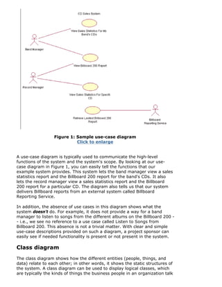
In my experience, almost every developer knows what this diagram is, yet
I find that most programmers draw the relationship lines incorrectly. For a
class diagram like the one in Figure 3,you should draw the inheritance
relationship1 using a line with an arrowhead at the top pointing to the
super class, and the arrowhead should a completed triangle. An
association relationship should be a solid line if both classes are aware of
each other and a line with an open arrowhead if the association is known
by only one of the classes.
Figure 3: A complete class diagram,
including the class object shown in Figure 2
Click to enlarge
In Figure 3, we see both the inheritance relationship and two association
relationships. The CDSalesReport class inherits from the Report class. A
CDSalesReport is associated with one CD, but the CD class doesn't know
anything about the CDSalesReport class. The CD and the Band classes
both know about each other, and both classes can be associated to one or
more of each other.
http://bronze.rational.com:8169/content/jun_03/f_UMLintro_db.jsp (4 of 11) [6/13/2003 12:58:48 PM]](https://image.slidesharecdn.com/umlbasics-160801134846/85/Uml-basics-4-320.jpg)
![A class diagram can incorporate many more concepts, which we will cover
later in this article series.
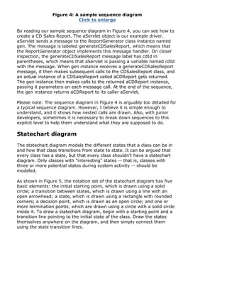
Sequence diagram
Sequence diagrams show a detailed flow for a specific use case or even
just part of a specific use case. They are almost self explanatory; they
show the calls between the different objects in their sequence and can
show, at a detailed level, different calls to different objects.
A sequence diagram has two dimensions: The vertical dimension shows
the sequence of messages/calls in the time order that they occur; the
horizontal dimension shows the object instances to which the messages
are sent.
A sequence diagram is very simple to draw. Across the top of your
diagram, identify the class instances (objects) by putting each class
instance inside a box (see Figure 4). In the box, put the class instance
name and class name separated by a space/colon/space " : " (e.g.,
myReportGenerator : ReportGenerator). If a class instance sends a
message to another class instance, draw a line with an open arrowhead
pointing to the receiving class instance; place the name of the
message/method above the line. Optionally, for important messages, you
can draw a dotted line with an arrowhead pointing back to the originating
class instance; label the return value above the dotted line. Personally, I
always like to include the return value lines because I find the extra details
make it easier to read.
Reading a sequence diagram is very simple. Start at the top left corner
with the "driver" class instance that starts the sequence. Then follow each
message down the diagram. Remember: Even though the example
sequence diagram in Figure 4 shows a return message for each sent
message, this is optional.
http://bronze.rational.com:8169/content/jun_03/f_UMLintro_db.jsp (5 of 11) [6/13/2003 12:58:48 PM]](https://image.slidesharecdn.com/umlbasics-160801134846/85/Uml-basics-5-320.jpg)

![shown at a very high level, with just the large-grain components, or it can
be shown at the component package level.2
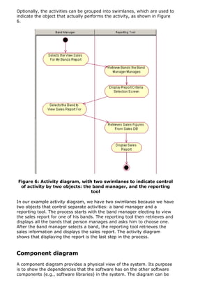
Modeling a component diagram is best described through an example.
Figure 7 shows four components: Reporting Tool, Billboard Service,
Servlet 2.2 API, and JDBC API. The arrowed lines from the Reporting Tool
component to the Billboard Service, Servlet 2.2 API, and JDBC API
components mean that the Reporting Tool is dependent on those three
components.
Figure 7: A component diagram shows interdependencies of
various software components the system comprises
Click to enlarge
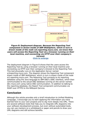
Deployment diagram
The deployment diagram shows how a system will be physically deployed
in the hardware environment. Its purpose is to show where the different
components of the system will physically run and how they will
communicate with each other. Since the diagram models the physical
runtime, a system's production staff will make considerable use of this
diagram.
The notation in a deployment diagram includes the notation elements used
in a component diagram, with a couple of additions, including the concept
of a node. A node represents either a physical machine or a virtual
machine node (e.g., a mainframe node). To model a node, simply draw a
three-dimensional cube with the name of the node at the top of the cube.
Use the naming convention used in sequence diagrams: [instance name] :
[instance type] (e.g., "w3reporting.myco.com : Application Server").](https://image.slidesharecdn.com/umlbasics-160801134846/85/Uml-basics-9-320.jpg)