ABC Consolidated Financial InfoABC Companys current financial inf.docxransayo
ABC Consolidated Financial InfoABC Company's current financial information (before/without expansion)Dec. 31,20X2Dec. 31,20X1Cash$ 50,000$ 70,000Accounts receivable (net)$ 120,000$ 180,000Merchandise inventory$ 350,000$ 280,000Property plant, & equipment$ 400,000$ 300,000Less: Accumulated depreciation$ (170,000)$ (100,000)Total assets$ 750,000$ 730,000Accounts payable$ 250,000$ 210,000Income taxes payable$ 40,000$ 10,000Common stock$ 240,000$ 240,000Retained earnings$ 220,000$ 270,000Total liabilities & stock, equity$ 750,000$ 730,000The firm's accrual-basis income statement revealed the following data:Sales$ 1,200,000Cost of goods sold$ 800,000selling and administrative expenses$ 250,000Depreciation expense$ 70,000Income taxes$ 30,000Dividends declared and paid during 20X2$ 100,000ABC purchased $100,000 of equipment for cash on August 14, 20X2(There was no interest expense.)
ABC Product informationBased on Chapter 5's exercise 5ABC's Product informationCurrent ProductExpansion Product (estimate)Selling Price$14.50?Units produced and expected to be sold80,0005,000Machine Hours40,0005,000Direct Materials$1.30 per unit$5.60 per unitDirect labor dollars needed per product$2.80 per unit$4.00 per unitVariable Factory Overhead$1.00 per Machine Hour$1.00 per Machine HourVariable Selling Expense$0.20 per unit$0.20 per unitTotal Fixed Costs:Fixed Factory Overhead$ 198,000Fixed Selling expenses$ 191,250
UNIVERSITY OF CALIFORNIA, SANTA CRUZ
BOARD OF STUDIES IN COMPUTER ENGINEERING
CMPE13/L: INTRODUCTION TO PROGRAMMING IN C
Lab 1: Compiling, Running, and Debugging
Introduction
This is the first lab in CMPE13. Here we will demonstrate the basics of compiling and running C
programs in the simulator and on the Uno32 hardware. We will also explore the tools we will
use and some of their features for debugging problems you might encounter.
Reading
• Document on compiler errors
• Document on Unix and Git
• Document on software installation (if you want to run everything on your own computer)
• Document on style guidelines
• Document on MPLAB X
• Document on serial communications
• K&R Preface and Introduction
• K&R Sections 1.0-1.2, 4.5, 4.11
Provided Files
• part1.c: This file contains code that performs a simple sorting algorithm on five randomly
generated numbers. Follow the setup procedures listed below, add the requested
documentation, and format the code to follow the provided style guidelines.
• part2.c: This file contains an empty main() to be filled with the exercises from section 1.2 of
K&R. In addition, you will be asked to modify these exercises to add some additional
functionality. Detailed steps are listed below.
• BOARD.c/h - Contains initialization code for the UNO32 along with standard #defines and
system libraries used. Also includes the standard fixed-width datatypes and error return values.
You will not be modifying these fi.
DVR Networking: How to Connect Your DVR to the LANChristian Watson
View step-by-step instructions for connecting your DVR to the LAN, along with screen shots.
http://www.supercircuits.com/resources/learn/dvr-networking-guide/connecting-your-dvr-to-the-lan
1. Packet Tracer – Configure End Devices
Objectives
Configure Various End Devices in Packet Tracer.
Background / Scenario
In this activity you will construct a simple Packet Tracer network and complete basic configuration of end
devices.
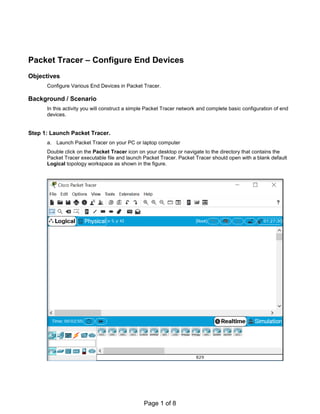
Step 1: Launch Packet Tracer.
a. Launch Packet Tracer on your PC or laptop computer
Double click on the Packet Tracer icon on your desktop or navigate to the directory that contains the
Packet Tracer executable file and launch Packet Tracer. Packet Tracer should open with a blank default
Logical topology workspace as shown in the figure.
Page 1 of 8
Lab 4: Configuring End devices
2. Step 2: Build the topology
1. Create the network shown below (If help is required, please refer to previous activities.).
a. Use port FastEthernet0/1 on the switch for PC0
b. Use port FastEthernet0/2 on the switch for PC1
c. Use port FastEthernet0/3 on the switch for Server0
2. Once the link lights all turn green, click on Server0. Then configure it as follows:
a. Click on the Desktop tab.
b. Click on the IP Configuration icon.
c. Click on the IP Address dialog box.
d. Type in 192.168.1.1 as the address and press enter.
e. A default value of 255.255.255.0 should appear in the Subnet Mask field.
f. Nothing else in this dialog box needs to be configured, so click the “X” in the upper right corner to
close the IP Configuration window.
g. Click the red “X” in the upper right corner to close the Server0 window.
3. Click on PC0. Then configure it as follows:
Page 2 of 8
3. a. Click on the Desktop tab.
b. Click on the IP Configuration icon.
c. Click on the IP Address dialog box.
d. Type in 192.168.1.2 as the address and press enter.
e. A default value of 255.255.255.0 should appear in the Subnet Mask field.
f. Nothing else in this dialog box needs to be configured, so click the “X” in the upper right corner to
close the IP Configuration window
g. Click on the icon labeled Command Prompt and the following prompt should appear:
h. Type the following command in the prompt: ping 192.168.1.1 and press enter.
i. If you have done everything correctly, you should see the following output. Your output could vary
a little but the reply statements should be there. If the replies are not there, try redoing the device
configuration to this point.
Page 3 of 8
4. j. Click the “X” next to the Command Prompt title bar.
k. Click the red “X” in the upper right corner to close the PC0 window.
4. Repeat the same configuration and ping steps from #3 on PC1, except use 192.168.1.3 as the IP address.
The results should be the same.
5. Finally, click on PC1 again.
a. Click on the Desktop tab, if it is not already open.
b. Click on the Web Browser icon.
c. Type 192.168.1.1 in the URL box and click the [GO] button.
d. You should observe the following. If you do not, repeat the earlier steps to confirm the
configuration. This happens because the web server feature is on by default in the server and PC1
just connected to the default page.
e. Click on a link and then use the front and back arrows to the left of the URL box to move forward
and backward through the pages.
f. When done, click the “X” next to the Web Browser title bar.
g. Click the red “X” in the upper right corner to close the PC0 window.
The next section involves some basic configuration of network devices, in this case a switch. Routers have the
same tabs as switches so their interface works the same way.
Page 4 of 8
5. 6. Click on Switch0, then click on the Config tab.
Note: Previously, a warning about not using the Config tab was given because it is not available on real
networking equipment, but we are explaining this tab for two reasons.
i. Some simple devices only have config tabs.
ii. The config tab can be useful for basic learning of commands, especially for beginners.
a. Clicking on the Config tab shows a list of components that can be configured on this device. We
are not going to cover what these components are, as that is learned in a networking course, but
we will show how to navigate and use the interface.
b. The Global Settings tab allows a user to change the name of a device that displays in the
workspace. It also allows for changing the internal name shown at the command line prompt as
well as buttons for saving, loading, exporting, and erasing configuration files.
Page 5 of 8
6. c. Double click in the Hostname dialog box highlighting the word Switch, type Central and press
enter. Packet Tracer will display the IOS commands necessary to accomplish the name change in
the Equivalent IOS Commands box. The commands displayed should be as follows:
Switch>enable
Switch#configure terminal
Enter configuration commands, one per line. End with CNTL/Z.
Switch(config)#hostname Central
Central(config)#
These would be the commands that would be entered to do the same thing from the
command line interface or CLI. If you didn’t know how to do this from the CLI, the
Config tab would show the commands to illustrate how it should be done.
d. Clicking on the FastEthernet0/1 label will bring up an Ethernet interface to be configured.
e. Notice the Equivalent IOS Commands box below. It shows a command of “interface
FastEthernet0/1” which would have been the command used to select the interface from the CLI.
Page 6 of 8
7. f. Select the CLI tab to switch to the CLI interface. Notice that the same commands that were in the
Equivalent IOS Commands box are listed in the CLI window.
g. Click right beside the command prompt at the bottom of the list that looks like this:
“Central(config-if)#”
h. Then type shutdown , and press enter twice
Central(config-if)#shutdown
Central(config-if)#
%LINK-5-CHANGED: Interface FastEthernet0/1, changed state to
administratively down
%LINEPROTO-5-UPDOWN: Line protocol on Interface FastEthernet0/1,
changed state to down
Central(config-if)#
This command just shut the interface down from the command line.
i. Click the red “X” in the upper right corner to close the Server CLI window. Notice how the link
lights for the connection between PC0 and Switch0 are red. Because the interface on the switch
was shut down, the connection is no longer active and shows red.
This covers some basic configuration and operation of end devices in Packet Tracer. Please save and
close the activity, then exit Packet Tracer.
Page 7 of 8
8. Lab Tasks
In-Lab Task 1:
Post-Lab Task 1:
Figure 1: Network
Part a: Design and implement following network in packet tracer and apply the
following configurations:
1. Assign IP address and subnet mask to server.
2. Assign IP address and subnet mask to PC0.
3. Assign IP address and subnet mask to PC1.
4. From PC0 ping server and PC1.
5. Access cisco server web browser page.
Use following IP addresses and subnet masks to all devices:
Device Interface IP address Subnet Mask
PC0 FastEthernet0/1 192.168.10.15 255.255.255.0
PC1 FastEthernet0/2 192.168.10.25 255.255.255.0
Server FastEthernet0/5 192.168.10.35 255.255.255.0
Part b: Apply the following configuration to switch:
1. Replace switch name with your own name
2. Turn off Interface FastEthernet0/1 and FastEthernet0/2 through command in
CLI.
Note: Attach screenshots of each step.
Page 8 of 8
Implement all steps mentioned in lab manual.
Write all steps implemented in lab in summarized form.