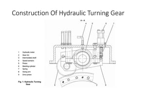
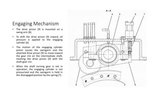
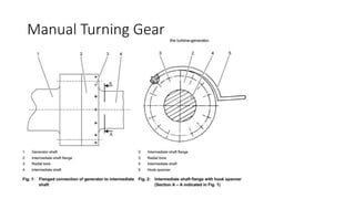
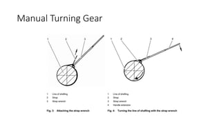
Turning Gear
Presented by
Abdullah Al Mamun
SDE (MMD)
Sirajganj 225MW CCPP (Unit-01)
Shaft Turning Gear
• After the turbine-generator has been shut down, the line of shafting
(gas turbine and generator) is transferred to turning gear mode and
rotated at low speed. This flow of air forced through the gas turbine
by the blading ensures uniform cool down of the machine.
• The turning gear rotates the turbine shaft and other accessory
equipment to make sure that there is uniform cool down of the shaft.
Otherwise it can result in sagging or bending of the turbine rotor.
During turbine starting also it is first put on the turning gear to break
the inertia slowly, if it's a cold start.
Shaft Turning Gear
• Turning gear speed is selected so as to ensure both sufficient air
throughput for uniform cooldown of the casing and to prevent blade
clattering.
• For mechanical design reasons, the turbine blades are seated loosely
in the rotor disk slots at room temperature. At very low shaft speeds
the blade roots shift slightly in their slots and clatter audibly. Above a
certain speed, centrifugal force firmly seats the blade roots.
Types of Turning Gear
• Hydraulic Turning Gear
• Manual Turning Gear
Hydraulic Turning Gear
• Jacking oil is supplied to the hydraulic motor and the swingarm
actuator. During operation of the gas turbine with the jacking oil
pump shut down, the hydraulic motor is supplied with lube oil via
swing check valve MBV35AA201 to prevent damage that is typical of
extended equipment standstills.
Construction Of Hydraulic Turning Gear
Hydraulic Motor
Technical Data
Parameter Value
Breakaway moment (ML) 880 Nm
Turn speed (nT) 120 rpm
Weight 200 KG
Engaging Mechanism
• The drive pinion (9) is mounted on a
swing arm (8).
• To shift the drive pinion (9) inward, oil
pressure is applied to the engaging
cylinder (6).
• The motion of the engaging cylinder
piston causes the swingarm and the
attached drive pinion (9) to move toward
the gear rim on the intermediate shaft,
meshing the drive pinion (9) with the
shaft gear rim.
• When the shaft turning gear is not in
operation, the engaging cylinder is not
pressurized and the swingarm is held in
the disengaged position by the spring (7).
Manual Turning Gear
Manual Turning Gear

Turning Gear.pptx

  • 1.
    Turning Gear Presented by AbdullahAl Mamun SDE (MMD) Sirajganj 225MW CCPP (Unit-01)
  • 2.
    Shaft Turning Gear •After the turbine-generator has been shut down, the line of shafting (gas turbine and generator) is transferred to turning gear mode and rotated at low speed. This flow of air forced through the gas turbine by the blading ensures uniform cool down of the machine. • The turning gear rotates the turbine shaft and other accessory equipment to make sure that there is uniform cool down of the shaft. Otherwise it can result in sagging or bending of the turbine rotor. During turbine starting also it is first put on the turning gear to break the inertia slowly, if it's a cold start.
  • 3.
    Shaft Turning Gear •Turning gear speed is selected so as to ensure both sufficient air throughput for uniform cooldown of the casing and to prevent blade clattering. • For mechanical design reasons, the turbine blades are seated loosely in the rotor disk slots at room temperature. At very low shaft speeds the blade roots shift slightly in their slots and clatter audibly. Above a certain speed, centrifugal force firmly seats the blade roots.
  • 4.
    Types of TurningGear • Hydraulic Turning Gear • Manual Turning Gear
  • 5.
    Hydraulic Turning Gear •Jacking oil is supplied to the hydraulic motor and the swingarm actuator. During operation of the gas turbine with the jacking oil pump shut down, the hydraulic motor is supplied with lube oil via swing check valve MBV35AA201 to prevent damage that is typical of extended equipment standstills.
  • 6.
  • 7.
  • 8.
  • 9.
    Technical Data Parameter Value Breakawaymoment (ML) 880 Nm Turn speed (nT) 120 rpm Weight 200 KG
  • 10.
    Engaging Mechanism • Thedrive pinion (9) is mounted on a swing arm (8). • To shift the drive pinion (9) inward, oil pressure is applied to the engaging cylinder (6). • The motion of the engaging cylinder piston causes the swingarm and the attached drive pinion (9) to move toward the gear rim on the intermediate shaft, meshing the drive pinion (9) with the shaft gear rim. • When the shaft turning gear is not in operation, the engaging cylinder is not pressurized and the swingarm is held in the disengaged position by the spring (7).
  • 12.
  • 13.