Download as PDF, PPTX


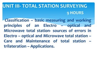
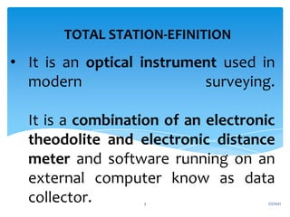
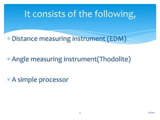
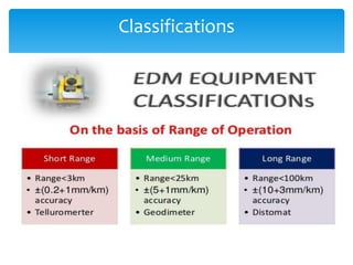
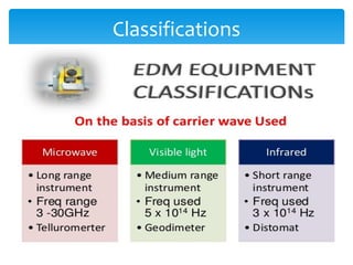
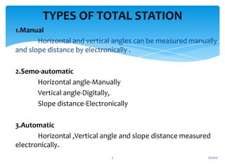

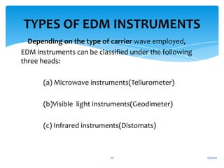


This document provides information about total station surveying. It discusses: - Total stations combine an electronic theodolite, electronic distance meter, and external computer for data collection. - Total stations can be classified as manual, semiautomatic, or automatic based on how angles and distances are measured. - Electro-optical total stations use light waves like visible light or infrared, while microwave total stations use radio waves to measure distances. - The document explains the operating principles, components, and potential sources of error for different types of total stations.