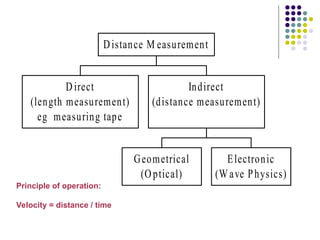
Electronic Distance
Measurement (EDM)
Direct
(length measurement)
eg measuring tape
Geometrical
(Optical)
Electronic
(W ave Physics)
Indirect
(distance measurement)
Distance M easurement
Principle of operation:
Velocity = distance / time
History of EDM
 Development of this type of technology started during
World War II with the development of RADAR (Radio
Detection and Ranging)
 Radars returned the distance to an object (and later
versions the speed of the object through the Doppler
shift) by timing the length of time the from the
transmission of a pulse to its return. Accuracy was set
by timing resolution (1sec=300meters)
 In 1949, Dr. Erik Bergstrand of Sweden introduced the
Geodimeter (Geodetic Distance Measurement) that
used light (550 nm wavelength) to measure geodetic
quality distances (instrument weighed 100kg)
History
 First introduced in the late 1950’s
 At first they were complicated, large, heavy,
and suited primarily for long distances
 Current EDM’s use either infrared (light
waves) or microwaves (radio waves)
 Microwaves require transmitters/receivers
at both ends
 Infrared use a transmitter at one end and a
reflecting prism at the other and are
generally used more frequently.
History of EDM
 Distance range was about 10km during daylight and 25km at night.
 Greater range during daytime was achieved by using radio waves, and
in Dr. T. L. Wadley, South Africa introduced the Tellurometer in 1957.
 Instrument used X-band radio waves (~10GHz)
 Receive and transmit ends looked similar (receiver actually re-
transmitted the signal) (The Geodimeter used one or more corner
cube reflectors.)
 Distances up to 50 km could be measured in daylight with this
instrument and later models.
EDM Properties
 They come in long (10-20 km), medium (3-10 km), and
short range (.5-3 km). Range limits up to 50 km
 They are typically mounted on top of a theodolite, but
can be mounted directly to a tribrach.
Total station
Total station
=
=
Theodolite with built in EDM
+
+
Microprocessor
Microprocessor
EDM Classifications
 Described by form of electromagnetic energy.
 First instruments were primarily microwave (1947)
 Present instruments are some form of light, i.e. laser or
near-infrared lights.
 Described by range of operation.
 Generally microwave are 30 - 50 km range. (med)
 Developed in the early 70’s, and were used for control
surveys.
 Light EDM’s generally 3 - 5 km range. (short)
 Used in engineering and construction
Geodimeter
 First units circa 1959 (50 kg each
for measurement unit and optics
9
Later model Geodimeter
 Example of a latter model Geodimeter (circa 1966)
Front and
back views
10
Telluometer
 Example of circa 1962 model.
Back and front of
instrument (9 kg with
case)
1970’s version (1.7kg)
Modern versions
 These types of measurements are now directly built into
the telescope assemblies of theodolites and you can see
these on most construction sites. The angles are now
also read electronically (compared to glass optical
circles).
 Modern example (circa 2000)
Corner cube reflector,
Infrared light source
used
 EDM is very useful in measuring distances that
are difficult to access or long distances.
 It measures the time required for a wave to sent
to a target and reflect back.
Operation:
A wave is transmitted and the
returning wave is measured to
find the distance traveled.
Principles of EDM
Transmitted Energy
Returned Energy
Principles of EDM
General Principle of EDM
 Electromagnetic energy
 Travels based on following relation:
f
V
λ
so
fλ
V 

• Intensity modulate EM energy to specific frequency
 Distances determined by calculating the number of wavelengths
traveled.
 Errors are generally small and insignificant for short distances.
 For longer distances they can be more important.
 Errors can be accounted for manually, or by the EDM if it has the
capability.
Velocity of light can be affected by:
 Temperature
Temperature
 Atmospheric pressure
Atmospheric pressure
 Water vapor content
Water vapor content
Principles of EDM
EDM Characteristics
EDM Characteristics
 750-1000 meters range
 Accurate to ±5mm + 5 ppm
 Operating temperature between -20 to +50 degrees centigrade
 1.5 seconds typical for computing a distance, 1 second when
tracking.
 Slope reduction either manual or automatic.
 Some average repeated measurements.
 Signal attenuation.
 Battery operated and can perform between 350 and 1400
measurements.
Prisms
Prisms
 Made from cube corners
 Have the property of reflecting rays back precisely in the
same direction.
 They can be tribrach-mounted and centered with an
optical plummet, or they can be attached
 To a range pole and held vertical on a point with the aid
of a bulls-eye level.
Prisms
Prisms
 Prisms are used with electro-optical EDM instruments to
reflect the transmitted signal
 A single reflector is a cube corner prism that has the
characteristic to reflecting light rays precisely back to the
emitting EDM instrument
 The quality of the prism is determined by the flatness of
the surface and the perpendicularity of the 90˚ surface
Accuracy
 Distance is computed by (no. of wavelengths
generated + partial wavelength)/2.
 Standard or Random errors are described in
the form of +(Constant + parts per million).
 Constant is the accuracy of converting partial
wavelength to a distance.
 ppm is a function of the accuracy of the length of
each wavelength, and the number of
wavelengths.
EDM Accuracy
Error & Accuracy
o-------------------------------o-------------o
A B C
Typical accuracy ± 5 mm + 5 ppm
Both the prism and EDM should be corrected for off-center characteristics.
The prism/instrument constant (about 30 to 40 mm) can be measured by
measure AC, AB, and BC and then constant = AC-AB-BC
Blunders:
• Incorrect ‘met’ settings
• Incorrect scale settings
• Prism constants ignored
• Incorrect recording settings
(e.g. horizontal vs. slope)
Sources of Error in EDM:
Personal:
• Careless centering of instrument and/or reflector
• Faulty temperature and pressure measurements
Instrumental
• Instrument not calibrated
• Electrical center
• Prism Constant (see next
slide)
Natural
• Varying ‘met’ along line
• Turbulence in air
A B C
Determination of System Measuring Constant
1. Measure AB, BC and AC
2. AC + K = (AB + K) + (BC + K)
3. K = AC- (AB + BC)
4. If electrical center is calibrated, K rep-
resents the prism constant. Good Practice:
Never mix prism
types and brands on
same project!!!
Calibrate regularly !!!
Systematic
Errors/Instrumentation Error
 Microwave
 Atmospheric conditions
 Temperature
 Pressure
 Humidity - must have wet bulb and dry bulb temperature.
 Multi-path
 Reflected signals can give longer distances
 Light
 Atmospheric conditions
 Temperature
 Pressure
 Prism offset
 Point of measurement is generally behind the plumb line.
 Today usually standardized as 30mm.
EDM instrument operation
1.Set up
 EDM instruments are inserted in to the tribrach
 Set over the point by means of the optical plummet
 Prisms are set over the remote station point
 The EDM turned on
 The height of the prism and the EDM should me
measured
EDM instrument operation
2.Aim
 The EDM is aimed at the prism by using either the built-
in sighting devices on the EDM
 Telescope (yoke-mount EDMs) will have the optical line
of sight a bit lower than the electronic signal
 When the cross hair is sight on target the electronic
signal will be maximized at the center of the prism
 Set the electronic signal precisely on the prism center
EDM instrument operation
3. Measure
 The slope measurement is accomplished by simply
pressing the measure button
 The displays are either liquid crystal (LCD) or light
emitting diode (LED)
 The measurements is shown in two decimals of a foot or
three decimals of a meter
 EDM with built in calculators can now be used to
compute horizontal and vertical distances, coordinate,
atmosphiric,curveture and prism constant corrections
EDM instrument operation
4. Record
 The measured data can be recorded in the field note
format
 Can be entered manually into electronic data collector
 The distance data must be accompanied by all relevant
atmospheric and instrumental correction factors
Topographic
Topographic
&
&
As Builts
As Builts
Monitoring
Monitoring
&
&
Control
Control
Construction Layout
Construction Layout
Uses

electronic distance measurement.jkghfppt

  • 1.
  • 2.
    Direct (length measurement) eg measuringtape Geometrical (Optical) Electronic (W ave Physics) Indirect (distance measurement) Distance M easurement Principle of operation: Velocity = distance / time
  • 3.
    History of EDM Development of this type of technology started during World War II with the development of RADAR (Radio Detection and Ranging)  Radars returned the distance to an object (and later versions the speed of the object through the Doppler shift) by timing the length of time the from the transmission of a pulse to its return. Accuracy was set by timing resolution (1sec=300meters)  In 1949, Dr. Erik Bergstrand of Sweden introduced the Geodimeter (Geodetic Distance Measurement) that used light (550 nm wavelength) to measure geodetic quality distances (instrument weighed 100kg)
  • 4.
    History  First introducedin the late 1950’s  At first they were complicated, large, heavy, and suited primarily for long distances  Current EDM’s use either infrared (light waves) or microwaves (radio waves)  Microwaves require transmitters/receivers at both ends  Infrared use a transmitter at one end and a reflecting prism at the other and are generally used more frequently.
  • 5.
    History of EDM Distance range was about 10km during daylight and 25km at night.  Greater range during daytime was achieved by using radio waves, and in Dr. T. L. Wadley, South Africa introduced the Tellurometer in 1957.  Instrument used X-band radio waves (~10GHz)  Receive and transmit ends looked similar (receiver actually re- transmitted the signal) (The Geodimeter used one or more corner cube reflectors.)  Distances up to 50 km could be measured in daylight with this instrument and later models.
  • 6.
    EDM Properties  Theycome in long (10-20 km), medium (3-10 km), and short range (.5-3 km). Range limits up to 50 km  They are typically mounted on top of a theodolite, but can be mounted directly to a tribrach. Total station Total station = = Theodolite with built in EDM Theodolite with built in EDM + + Microprocessor Microprocessor
  • 7.
    EDM Classifications  Describedby form of electromagnetic energy.  First instruments were primarily microwave (1947)  Present instruments are some form of light, i.e. laser or near-infrared lights.  Described by range of operation.  Generally microwave are 30 - 50 km range. (med)  Developed in the early 70’s, and were used for control surveys.  Light EDM’s generally 3 - 5 km range. (short)  Used in engineering and construction
  • 8.
    Geodimeter  First unitscirca 1959 (50 kg each for measurement unit and optics
  • 9.
    9 Later model Geodimeter Example of a latter model Geodimeter (circa 1966) Front and back views
  • 10.
    10 Telluometer  Example ofcirca 1962 model. Back and front of instrument (9 kg with case) 1970’s version (1.7kg)
  • 11.
    Modern versions  Thesetypes of measurements are now directly built into the telescope assemblies of theodolites and you can see these on most construction sites. The angles are now also read electronically (compared to glass optical circles).  Modern example (circa 2000) Corner cube reflector, Infrared light source used
  • 12.
     EDM isvery useful in measuring distances that are difficult to access or long distances.  It measures the time required for a wave to sent to a target and reflect back.
  • 13.
    Operation: A wave istransmitted and the returning wave is measured to find the distance traveled. Principles of EDM
  • 14.
  • 15.
    General Principle ofEDM  Electromagnetic energy  Travels based on following relation: f V λ so fλ V   • Intensity modulate EM energy to specific frequency
  • 16.
     Distances determinedby calculating the number of wavelengths traveled.  Errors are generally small and insignificant for short distances.  For longer distances they can be more important.  Errors can be accounted for manually, or by the EDM if it has the capability. Velocity of light can be affected by: Velocity of light can be affected by:  Temperature Temperature  Atmospheric pressure Atmospheric pressure  Water vapor content Water vapor content Principles of EDM
  • 17.
    EDM Characteristics EDM Characteristics 750-1000 meters range  Accurate to ±5mm + 5 ppm  Operating temperature between -20 to +50 degrees centigrade  1.5 seconds typical for computing a distance, 1 second when tracking.  Slope reduction either manual or automatic.  Some average repeated measurements.  Signal attenuation.  Battery operated and can perform between 350 and 1400 measurements.
  • 18.
    Prisms Prisms  Made fromcube corners  Have the property of reflecting rays back precisely in the same direction.  They can be tribrach-mounted and centered with an optical plummet, or they can be attached  To a range pole and held vertical on a point with the aid of a bulls-eye level.
  • 19.
    Prisms Prisms  Prisms areused with electro-optical EDM instruments to reflect the transmitted signal  A single reflector is a cube corner prism that has the characteristic to reflecting light rays precisely back to the emitting EDM instrument  The quality of the prism is determined by the flatness of the surface and the perpendicularity of the 90˚ surface
  • 20.
    Accuracy  Distance iscomputed by (no. of wavelengths generated + partial wavelength)/2.  Standard or Random errors are described in the form of +(Constant + parts per million).  Constant is the accuracy of converting partial wavelength to a distance.  ppm is a function of the accuracy of the length of each wavelength, and the number of wavelengths.
  • 21.
  • 22.
    Error & Accuracy o-------------------------------o-------------o AB C Typical accuracy ± 5 mm + 5 ppm Typical accuracy ± 5 mm + 5 ppm Both the prism and EDM should be corrected for off-center characteristics. The prism/instrument constant (about 30 to 40 mm) can be measured by measure AC, AB, and BC and then constant = AC-AB-BC Blunders: • Incorrect ‘met’ settings • Incorrect scale settings • Prism constants ignored • Incorrect recording settings (e.g. horizontal vs. slope)
  • 23.
    Sources of Errorin EDM: Personal: • Careless centering of instrument and/or reflector • Faulty temperature and pressure measurements Instrumental • Instrument not calibrated • Electrical center • Prism Constant (see next slide) Natural • Varying ‘met’ along line • Turbulence in air
  • 24.
    A B C Determinationof System Measuring Constant 1. Measure AB, BC and AC 2. AC + K = (AB + K) + (BC + K) 3. K = AC- (AB + BC) 4. If electrical center is calibrated, K rep- resents the prism constant. Good Practice: Never mix prism types and brands on same project!!! Calibrate regularly !!!
  • 25.
    Systematic Errors/Instrumentation Error  Microwave Atmospheric conditions  Temperature  Pressure  Humidity - must have wet bulb and dry bulb temperature.  Multi-path  Reflected signals can give longer distances  Light  Atmospheric conditions  Temperature  Pressure  Prism offset  Point of measurement is generally behind the plumb line.  Today usually standardized as 30mm.
  • 26.
    EDM instrument operation 1.Setup  EDM instruments are inserted in to the tribrach  Set over the point by means of the optical plummet  Prisms are set over the remote station point  The EDM turned on  The height of the prism and the EDM should me measured
  • 27.
    EDM instrument operation 2.Aim The EDM is aimed at the prism by using either the built- in sighting devices on the EDM  Telescope (yoke-mount EDMs) will have the optical line of sight a bit lower than the electronic signal  When the cross hair is sight on target the electronic signal will be maximized at the center of the prism  Set the electronic signal precisely on the prism center
  • 28.
    EDM instrument operation 3.Measure  The slope measurement is accomplished by simply pressing the measure button  The displays are either liquid crystal (LCD) or light emitting diode (LED)  The measurements is shown in two decimals of a foot or three decimals of a meter  EDM with built in calculators can now be used to compute horizontal and vertical distances, coordinate, atmosphiric,curveture and prism constant corrections
  • 29.
    EDM instrument operation 4.Record  The measured data can be recorded in the field note format  Can be entered manually into electronic data collector  The distance data must be accompanied by all relevant atmospheric and instrumental correction factors
  • 30.

Editor's Notes

  • #8 circa - approximately
  • #17 Parts Per Million (ppm): Parts per million is a ratio used to express accuracy as a proportion of the measured distance. In this case, the accuracy is stated as 2 ppm, which means that for every million parts of the measured distance, the total station has an accuracy of 2 parts. Attenuation is a general term that refers to any reduction in the strength of a signal
  • #30 Topo / Pickup – pre-design work As built – post design Construction Layout Monitoring – note the fixed post. Control – the establishment of a net work from which to base future surveys.