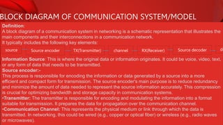
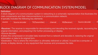
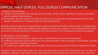
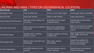
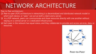
COMMUNICATION AND NETWORKING
BLOCK DIAGRAM OF COMMUNICATION SYSTEM/MODEL
Definition:
A block diagram of a communication system in networking is a schematic representation that illustrates the
main components and their interconnections in a communication network.
It typically includes the following key elements:
Information Source: This is where the original data or information originates. It could be voice, video, text,
or any form of data that needs to be transmitted.
Source encoder:-
This process is responsible for encoding the information or data generated by a source into a more
efficient and compact form for transmission. The source encoder's main purpose is to reduce redundancy
and minimize the amount of data needed to represent the source information accurately. This compression
is crucial for optimizing bandwidth and storage capacity in communication systems.
•Transmitter: The transmitter is responsible for encoding and modulating the information into a format
suitable for transmission. It prepares the data for propagation over the communication channel.
•Communication Channel: This represents the physical medium or link through which the data is
transmitted. In networking, this could be wired (e.g., copper or optical fiber) or wireless (e.g., radio waves
or microwaves).
source Source encoder TX(Transmitter) channel RX(Receiver) Source decoder de
BLOCK DIAGRAM OF COMMUNICATION SYSTEM/MODEL
Definition:
A block diagram of a communication system in networking is a schematic representation that illustrates the
main components and their interconnections in a communication network.
It typically includes the following key elements:
•
•Receiver: The receiver is responsible for demodulating and decoding the received signals, recovering the
original information, and preparing it for further processing or display.
•Source decoder:
It takes the compressed or encoded data received from a network and decodes it, restoring the original
information or data to its original form.
•Destination: This is where the information is ultimately delivered or utilized. It could be a computer, a
phone, a display device, or any equipment that receives and processes the data.
source Source encoder TX(Transmitter) channel RX(Receiver) Source decoder de
SIMPLEX, HALF DUPLEX, FULL DUPLEX COMMUNICATION
1.Simplex Communication:
 Simplex communication is a one-way communication mode in which data flows in only one direction,
from the sender to the receiver.
 The receiver can only receive the data and cannot send a response or acknowledgment back to the
sender. It is similar to a "one-way street" for data transmission.
Example: Radio or television broadcasting is a typical example of simplex communication. In these cases,
the broadcasting station sends signals, and multiple receivers (e.g., radios or TVs) receive the information,
but there is no direct interaction or feedback from the receivers to the broadcaster during the broadcast.
2. Half Duplex Communication:
 In half-duplex communication, data can flow in both directions, but not simultaneously.
 It allows for two-way communication, but not at the same time. When one party is transmitting, the other
party must wait to receive or respond.
 It is similar to a "walkie-talkie" communication, where you press a button to talk and release it to listen.
Example: Citizen's band (CB) radios and many two-way radios used by first responders, such as police or
firefighters, operate in half-duplex mode. Users take turns transmitting and receiving, but they cannot do
SIMPLEX, HALF DUPLEX, FULL DUPLEX COMMUNICATION
3.Full Duplex Communication:
 Full duplex communication is a two-way communication mode that allows data to flow in both directions
simultaneously.
 This means that both the sender and receiver can transmit and receive data simultaneously. It is like a
"two-way street" for data transmission.
Example: Traditional telephone conversations over a landline or cellular network are excellent examples of
full-duplex communication. During a phone call, both parties can speak and listen at the same time,
enabling natural and real-time conversations.
LAN,MAN AND WAN ( TYPES ON GEOGRAPHICAL LOCATION)
Characteristic LAN MAN WAN
Geographic Scope Small, localized area Covers a city or metro region Covers large regions or globally
Size and Scale Small-scale network Medium-scale network Large-scale network
Typical Speed and Performance
High data transfer speeds and
low latency
Good data transfer speeds,
moderate latency
Variable data transfer speeds,
higher latency
Ownership and Control
Often owned and controlled by a
single entity
May involve collaboration
between multiple entities
Relies on services from multiple
ISPs and can involve shared
control
Connectivity Range
Typically within a building,
campus, or home
Citywide coverage connecting
multiple LANs
Spans long distances, connecting
LANs, MANs, and remote
locations
Technologies Used
Ethernet, Wi-Fi, and other local
technologies
Fiber optics, wireless
technologies
Leased lines, satellite, the
Internet, and various long-
distance technologies
Common Applications
Local office networks, home
networks
City-wide internet services,
campus networks
Global internet, multinational
corporate networks
TRANSMISSION MEDIA
Definition:
 Transmission media, in the context of computer networking and telecommunications, refers to the
physical or wireless means by which data is transmitted from one device to another.
 It serves as the pathway that allows data to travel between devices, such as computers, smartphones,
or servers.
Transmission media can be categorized into two main types:
1.Wired Transmission Media: These include physical cables and wires that conduct electrical signals.
Common examples of wired transmission media include:
a. Twisted Pair Cable: Utilizes twisted pairs of copper wires, commonly used in Ethernet connections.
b. Coaxial Cable: Features a central conductor surrounded by insulation and a metallic shield, often
used in cable television.
c. Fiber Optic Cable: Uses strands of glass or plastic fibers to transmit data as pulses of light, offering
high data transmission rates.
2. Wireless Transmission Media: These do not require physical cables and instead rely on electromagnetic
waves for data transmission.
Wireless transmission media includes:
a. Radio Waves: Used in technologies like Wi-Fi and Bluetooth to transmit data over the air.
b. Microwaves: Utilized for long-distance point-to-point communication, such as in satellite links.
TRANSMISSION MEDIA
1.Wired Transmission Media:
a. Twisted Pair Cable:-
 In networking, a twisted pair cable is a type of copper cable that consists of pairs of insulated copper
wires twisted together.
 These twisted pairs are used to transmit electrical signals, and they are a common medium for data
communication in Ethernet and other networking technologies.
Twisted pair cables come in two main categories:
1.Unshielded Twisted Pair (UTP):
 UTP cables are the most common type of twisted pair cables used in networking.
 They do not have any additional shielding around the twisted pairs.
 UTP cables are categorized into different "categories" or "CAT" ratings, such as Cat 5e, Cat 6, Cat 6a,
and Cat 7, with each category offering varying levels of performance and data transmission capabilities.
 They are widely used for connecting computers, switches, routers, and other network devices in local
area networks (LANs).
2. Shielded Twisted Pair (STP):
 STP cables have an additional layer of shielding around the twisted pairs to provide better protection
against electromagnetic interference (EMI) and radio frequency interference (RFI).
 STP cables are less common in home and office networking but can be used in environments where
TRANSMISSION MEDIA
1.Wired Transmission Media:
a. Twisted Pair Cable:-
Advantages:
•Cost-Effective: Twisted pair cables are relatively inexpensive to manufacture and install, making them a
cost-effective choice for network cabling solutions.
•Flexibility: Twisted pair cables are flexible and easy to work with, allowing for convenient installation in
various environments, including homes and offices.
•Interference Resistance: The twisting of pairs in the cable helps reduce electromagnetic interference
(EMI) and radio frequency interference (RFI), leading to better signal quality and reliability.
•Multiple Categories: Twisted pair cables come in various categories (e.g., Cat 5e, Cat 6) with different
performance levels, allowing you to choose the right category for your specific networking requirements.
Disadvantages:-
•Limited distance
•Vulnerability to crosstalk
•Limited bandwidth
•Susceptibility to EMI and RFI
•Performance degradation over distance
TRANSMISSION MEDIA
1.Wired Transmission Media:
a. Coaxial Cable:-
Coaxial cable is a type of electrical cable consisting of a central conductor, an insulating layer, a metallic
shield, and an outer insulating layer, used for transmitting high-frequency electrical signals and data.
Advantages of coaxial cable:
•High bandwidth
•Better signal quality
•Resistance to interference
•Suitable for long distances
Disadvantages of coaxial cable:
•Bulky and less flexible
•Installation can be more complex
•Limited support for high data rates
•Vulnerable to signal loss over long distances
------------
Note:
Thicknet (10BASE5=10Mbps for 500 meter and uses base band. It means it uses entire bandwidth for
transmission ):
TRANSMISSION MEDIA
1.Wired Transmission Media:
a. Optical cable:-
 Optical fiber is a thin, flexible, and transparent
strand of glass or plastic that is used to transmit
data as pulses of light.
 It is a crucial technology in telecommunications
and networking because it allows for high-speed,
long-distance data transmission.
 The core of the optical fiber is designed to carry
light signals, and the surrounding cladding helps
to keep the light within the core through multiple
reflections.
 This technology enables the fast and efficient
transfer of data, making it a key component in the
internet and many other communication systems.
Advantages
•High Data Transmission Rates
•Durability
•Low Latency
•Future-Proofing
•Reduced Signal Degradation
•High Bandwidth
Disadvantages:
•Higher installation and equipment costs
•Fragility, requiring careful handling
•Limited availability in remote areas
•Difficulty in splicing and connecting fibers
•Vulnerability to physical damage (e.g., bending or
breaking)
•Specialized expertise needed for installation and
maintenance
•Incompatibility with some existing infrastructure
TRANSMISSION MEDIA
1.Wired Transmission Media:
a. Optical cable:-
Components:
Plastic coating:
The plastic coating in optical fiber refers to a protective layer made of plastic (often acrylate or polymer
materials) that surrounds the glass or silica core of the optical fiber.
Cladding:
The cladding's purpose is to reflect and contain the light signals within the core by using the principle of
total internal reflection. This design allows the optical fiber to efficiently transmit light signals over long
distances without significant signal loss, as the cladding helps keep the light waves confined to the core.
Plastic buffer:-
A plastic buffer in optical fiber refers to a protective layer of plastic material that surrounds the cladding and
core of the optical fiber. This plastic buffer serves multiple purposes, including mechanical protection,
insulation, and isolation of the fiber from external elements such as moisture and contaminants.
Fiber core:-
The fiber core in an optical fiber is the central part of the fiber through which light signals are transmitted. It
is typically made of high-purity glass or silica and has a higher refractive index than the surrounding
TRANSMISSION MEDIA
1.Wireless Transmission Media:
a. Radio wave
 A radio wave is a type of electromagnetic wave used in wireless communication.
 It is a form of energy that travels through the air, space, or other mediums.
 Radio waves have longer wavelengths and lower frequencies than visible light, and they are used for
various purposes, including broadcasting radio and television signals, wireless communication (like Wi-
Fi and cell phones), and radar systems.
 They can carry information by modulating their amplitude, frequency, or phase and are an essential part
of modern wireless technology.
Microwave:-
 In networking, "microwave" typically refers to microwave communication, which is a method of
transmitting data wirelessly using microwave radio signals.
 This technology involves the use of high-frequency electromagnetic waves in the microwave range,
usually in the gigahertz (GHz) frequency range.
 Microwave communication is commonly used for point-to-point communication links between network
nodes, such as buildings, cell towers, or data centers.
 It offers high data transmission rates and low latency, making it suitable for backhaul connections and
providing connectivity in situations where laying physical cables is challenging or impractical.
TRANSMISSION MEDIA
1.Wireless Transmission Media:
a. Satellite:
 A satellite is a human-made object that orbits around a celestial body, often the Earth.
 In the context of communication and technology, a satellite typically refers to an artificial satellite placed
in orbit around the Earth.
 These satellites are used for various purposes, including telecommunications, weather monitoring,
navigation (GPS), scientific research, and more. Communication satellites, for example, play a crucial
role in relaying signals for television, internet, and telephone services over long distances by
transmitting and receiving signals to and from ground stations.
-----------------------------------------------------------------------------
Note: Some other can be:
Wifi,Bluetooth,IR etc.
TRANSMISSION IMPAIRMENTS
Definition:
 Transmission impairments in networking refer to any factors or issues that degrade the quality of data
as it is transmitted over a communication channel.
 These impairments can occur during the transmission of data from one point to another and can result
in errors, signal degradation, or loss of information.
Types:
1. Jitter:
Variability in the timing of signal arrivals. Jitter can cause problems in real-time applications like
voice and video communication.
2. echo:
In data communication, an "echo impairment" refers to a situation where a portion of the transmitted
signal is reflected back to the sender with a delay, creating a delayed duplicate of the original signal.
This echo can occur due to various reasons, such as impedance mismatches, signal reflections, or hybrid
circuit imbalances in the communication path.
3.bandwidth:
In communication, bandwidth refers to the range of frequencies or the capacity of a communication
channel to transmit data. It represents the difference between the highest and lowest frequencies that a
channel or medium can carry. A wider bandwidth can transmit more data, while a narrower bandwidth can
TRANSMISSION IMPAIRMENTS
3.crosstalk:
Crosstalk impairment in data communication refers to the undesired transfer of signals or interference
between adjacent or nearby communication channels, cables, or conductors.
It occurs when the electrical or electromagnetic fields of one channel affect and distort the signals in
another channel, resulting in signal degradation or errors.
4. Distortion:
Distortion impairment in data communication refers to the alteration or corruption of a signal as it
travels through a communication channel, causing a change in the signal's characteristics.
This distortion can manifest in various forms, such as amplitude distortion, phase distortion, or frequency
distortion, and it may result from a range of factors, including noise, interference, signal attenuation, and
signal dispersion.
5.Noise:
Noise impairment in data communication refers to unwanted and random electrical or electromagnetic
interference that disrupts the quality and integrity of signals as they are transmitted from a sender to a
receiver. Noise can introduce errors, distortions, or additional signals into the communication channel,
making it difficult to accurately receive and interpret the intended data.
NETWORK ARCHITECTURE
Peer to Peer architecture:-
 Peer-to-peer (P2P) architecture in networking is a decentralized and distributed network model in
which each device, or "peer," can act as both a client and a server.
 In a P2P network, peers can communicate and share resources directly with one another without
relying on a central server or a dedicated infrastructure.
 Each peer in the network has equal status, and they collaborate to provide and access services, data, or
resources.
NETWORK ARCHITECTURE
Key characteristics of P2P architecture include:
1. Decentralization:There is no central authority or server controlling the network. Peers operate
independently and autonomously.
2. Resource Sharing: Peers can share files, data, or services with other peers in a direct and distributed
manner.
3. Scalability: P2P networks can easily scale as more peers join, making them suitable for large and
dynamic networks.
4. Redundancy: Since there is no single point of failure, P2P networks can be robust and fault-tolerant.
P2P architecture is commonly used in applications like file sharing (e.g., BitTorrent), voice and video
communication (e.g., Skype), and distributed computing (e.g., SETI@home). It is especially well-suited for
scenarios where a centralized server is not necessary or where a more decentralized, fault-tolerant
structure is preferred.
NETWORK ARCHITECTURE
Client server architecture:-
Client-server architecture is a network model used in computer
systems and networking where computing tasks and services are
distributed between two types of entities: clients and servers.
- Clients:
Clients are devices or software applications that request services,
resources, or data from servers.
They typically run on end-user devices, such as personal
computers, smartphones, or tablets.
Clients initiate communication with servers to access information
or perform tasks.
Examples include web browsers requesting web pages from web
servers or email clients retrieving emails from email servers.
TERMS IN NETWORK ARCHITECTURE
IP address:-
 The address assigned to a network connection is known as an IP address.
 An IP address does not uniquely identify a device on a network, but it does specify a specific network
connection.
 IP addresses are assigned by the network administrator or by the internet service provider.
 An IP address is a numerical label assigned to each devices participating in a computer network that
uses the internet protocol for communication. IP address is a logical address.
 It is a network layer address (layer 3). It is in the form of internet number which is separated by dot (.).
 It includes a set of rules and performing routing function.
For Example, 192.168.10.26 and chooses a path for sending data. It is address of our computer on
internet. IP address is actually used while receiving emails, message, visiting websites, downloading and
uploading.
Through computer, mobile opening YouTube, YouTube is sending all the related data to IP address.
IP address is of two types: a) Ipv4 b) Ipv6
TERMS IN NETWORK ARCHITECTURE
IPV4:-
TERMS IN NETWORK ARCHITECTURE
IPV4:-
127.0.0.1 private for experiment local server or loop back testing(Loopback testing, also known as
loopback testing, is a method used in networking and telecommunications to test the functionality and
performance of a communication system or device. ). All computers use this address as their own, but it
doesn't let computer communicates with other devices as a real IP address does.
IP address has two parts network number and host number
TERMS IN NETWORK ARCHITECTURE
IPV6:-
An ipv6 address is a 128 bit binary address displayed as 32 hexadecimal digits.
So 16 × 8 = 128 bit (0-FFFF) = 65535
Colons separate entries in a series of 16 bit hexadecimal fields.
2128 devices can be connected.
Example of IPV6= FDEC:BA98:7654:3210:ADBF:BBFF:2922:FFFF
Example: 2001:0db8:0000:0000:0000: ff00:0042:7879
TERMS IN NETWORK ARCHITECTURE
Subnet mask:
 A subnet mask is a 32-bit number used in computer networking to divide an IP address into network
and host portions.
 It plays a crucial role in the process of subnetting, which involves breaking down a larger IP network
into smaller, more manageable subnetworks or subnets.
 The subnet mask is used to determine which part of an IP address identifies the network and which
part identifies the specific device (host) within that network.
TERMS IN NETWORK ARCHITECTURE
Subnet mask:
Network number is used to identify the network to which the computer is connected and the host
number is used to identify the particular machine connected to that network. Each of the computers
connected to a single networking system must have a unique IP address, which is defined and assigned
by the network administrator.
CLASS A: N.H.H.H = 255.0.0.0 Subnet mask
CLASS B: N.N.H.H. = 255.255.0.0 Subnet mask
CLASS C: N.N.N.H = 255.255.255.0 Subnet mask
255 represents the network and 0 represents host
Network = collection/group of hosts
Host = single pc or computer
--------------------------------------------------------
class D and E are not used for subnetting.
They are used for special purpose.
TERMS IN NETWORK ARCHITECTURE
How to assign Subnet mask:
For the subnet to work, an IP address has two parts.
The first part of an IP address is used as a network address, the last part as a host address.
If you take the example 192.168.123.132 , which belongs to class C(CLASS C: N.N.N.H = 255.255.255.0
Subnet mask ), as we divide it into these two parts,
you get 192.168.123. Network .132 Host
or 192.168.123.0 - network address.
0.0.0.132 - host address.
CLASS A: N.H.H.H = 255.0.0.0 Subnet mask
CLASS B: N.N.H.H. = 255.255.0.0 Subnet mask
CLASS C: N.N.N.H = 255.255.255.0 Subnet mask
255 represents the network and 0 represents host
Network = collection/group of hosts
Host = single pc or computer
TERMS IN NETWORK ARCHITECTURE
How to assign Subnet mask:
-----------------------------------------
For this subnet mask is 255.255.255.0. Lining up the IP address and the subnet mask together, the
network, and host portions of the address can be separated: 11000000.10101000.01111011.10000100 - IP
address (192.168.123.132) 11111111.11111111.11111111.00000000 - Subnet mask (255.255.255.0)
The first 24 bits (the number of ones in the subnet mask) are identified as the network address. The last 8
bits (the number of remaining zeros in the subnet mask) are identified as the host address.
It gives you the following addresses:
11000000.10101000.01111011.00000000 - Network address (192.168.123.0)
00000000.00000000.00000000.10000100 - Host address (000.000.000.132)
So now you know, for this example using a 255.255.255.0 subnet mask, that the network ID is
192.168.123.0, and the host address is 0.0.0.132. When a packet arrives on the 192.168.123.0 subnet (from
the local subnet or a remote network), and it has a destination address of 192.168.123.132, your
computer will receive it from the network and process it.
CLASS A: N.H.H.H = 255.0.0.0 Subnet mask
CLASS B: N.N.H.H. = 255.255.0.0 Subnet mask
CLASS C: N.N.N.H = 255.255.255.0 Subnet mask
255 represents the network and 0 represents
host
Network = collection/group of hosts
Host = single pc or computer
TERMS IN NETWORK ARCHITECTURE
Gateway:-
 In networking, a "gateway" refers to a device or a software component that connects two or more
networks, enabling data to flow between them.
 Gateways serve as entry and exit points for data as it moves between different networks, often with
distinct protocols, addressing schemes, or communication methods.
Key points about gateways in networking:
1. Network Interconnection:Gateways link networks with different architectures or communication
protocols, facilitating the exchange of data between them.
2. Protocol Conversion: They can translate data from one network's format to another, ensuring
compatibility between networks.
3. Traffic Routing: Gateways determine the most efficient path for data to travel from the source network
to the destination network.
4. Security:-They often serve as security checkpoints, filtering and monitoring data to protect networks
from unauthorized access or threats.
5. Internet Gateway: In the context of home or office networks, an Internet gateway connects the local
network to the wider internet, allowing devices to access online resources.
TERMS IN NETWORK ARCHITECTURE
MAC:-
 A MAC address, which stands for "Media Access Control address," is a unique identifier assigned to a
network interface card (NIC) or network adapter in a computer or other networked device. It serves as a
hardware address that distinguishes devices on a local area network (LAN).
 MAC addresses are typically assigned by the manufacturer and are used for communication within the
same network segment.
A MAC address is a 12-character hexadecimal number(48 bits), often displayed in a format like
"00:1A:2B:3C:4D:5E." The address is divided into six pairs of two hexadecimal digits, separated by colons or
hyphens.
Example of a MAC address: "00:1A:2B:3C:4D:5E"
Each NIC or network adapter has a globally unique MAC address. This uniqueness is important for
ensuring that data is accurately sent to and received by the correct device within the same network.
MAC addresses are used at the data link layer of the OSI model and are essential for local network
communication, such as Ethernet or Wi-Fi. They play a vital role in data packet delivery within a local
TERMS IN NETWORK ARCHITECTURE
Internet,Intranet and Extranet:-
Aspect Internet Intranet Extranet
Accessibility
Public, accessible to anyone
with an internet connection.
Private, accessible only to
authorized users within a
specific organization.
A mix of public and private
access. It is shared with select
external parties.
Purpose
Global communication and
information sharing.
Internal communication and
collaboration within an
organization.
Collaborative communication
with specific external partners,
customers, or suppliers.
Security
Limited control over security;
relies on encryption and
authentication.
High level of control over
security, often protected by
firewalls and access restrictions.
Secure, with varying levels of
access control to protect
sensitive information.
Content
Hosts public websites, email,
social media, and various online
services.
Contains internal documents,
databases, HR information, and
company-specific resources.
Shares specific data and
resources with authorized
external parties.
Open to the general public and
Access is typically restricted to
employees or authorized Accessible to authorized
TERMS IN NETWORK ARCHITECTURE
Internet,Intranet and Extranet:-
NETWORK TOOLS
Packet tracer:-
 Packet Tracer is a network simulation and visualization tool developed by
Cisco Systems.
 It is used in the field of networking and telecommunications to design,
configure, and troubleshoot computer networks.
 Packet Tracer provides a virtual environment in which users can create and
experiment with network topologies, devices, and protocols without the need
for physical hardware.
Key features:
1.Network Modeling: Users can design and build network topologies,
incorporating various network devices such as routers, switches, firewalls, and
end-user devices.
2.Configuration: It allows users to configure network devices with real-world
commands and settings, providing a practical learning experience.
3.Simulation: Packet Tracer simulates network behavior, enabling users to test
network functionality, troubleshoot issues, and observe how data packets move
NETWORK TOOLS
Remove login:-
Remote login, often referred to as "remote access" or "remote desktop," is a technology that allows a
user to access and control a computer or network from a remote location, typically over a network or the
internet. This enables a user to interact with a computer as if they were physically present at the remote
system.
Key points about remote login:
1. Access from Anywhere:Remote login allows a user to connect to a computer or network from a
different location, providing flexibility and convenience.
2. Control and Interaction: It provides the ability to control the remote computer, run applications, access
files, and perform tasks as if the user were sitting in front of the machine.
3. Use Cases: Remote login is used for various purposes, including technical support, system
administration, remote work, and accessing resources on a network from a distant location.
4. Security:Security measures, such as encryption and authentication, are essential to protect the privacy
and integrity of the remote session.
5. Examples: Common remote login technologies include Remote Desktop Protocol (RDP) for Windows,
Secure Shell (SSH) for Unix-based systems, and virtual private networks (VPNs) for secure remote access.
NETWORK ARCHITECTURE
Client server architecture:-
- Servers:
Servers are powerful computers or software applications that provide services, resources, or data in
response to requests from clients. They are designed to be always available and capable of handling
multiple client requests simultaneously. Servers can be specialized for specific tasks, like web servers,
email servers, file servers, or database servers.
In a client-server architecture, clients and servers communicate over a network, with the server responding
to client requests. This model allows for centralized management, efficient resource sharing, and
scalability. It is widely used in various networked applications and services, such as websites, email
systems, databases, and cloud computing.
NETWORKING DEVICES
NIC
1.Connection to the Network: NICs are the hardware components that
physically connect computers and devices to a network, enabling them to
communicate with each other and access network resources.
2.MAC Address: Each NIC has a unique MAC address, which is essential for
identifying devices on the network and ensuring that data packets are
delivered to the correct destination.
3.Types and Compatibility: NICs come in various types, including Ethernet
NICs, Wireless NICs (Wi-Fi), and Fiber Channel NICs. Choosing the right type
of NIC depends on the network technology and device requirements.
4.Data Transmission: NICs are responsible for transmitting and receiving
data packets, handling error checking, and ensuring the proper flow of data in
and out of the device.
5.Speed and Duplex Modes: NICs come with different speed ratings, from
10/100 Mbps to Gigabit or 10 Gbps. They also support various duplex modes,
such as half-duplex and full-duplex, impacting the efficiency of data transfer.
6.Device Drivers: NICs require specific device drivers to function properly.
These drivers facilitate communication between the operating system and the
NIC, ensuring seamless network connectivity.
MODEM
Definition: A MODEM, short for Modulator-Demodulator, is a hardware
device that translates digital data from a computer into analog signals for
transmission over analog communication lines and vice versa, converting
incoming analog signals back into digital data for the computer to interpret.
1.Data Transmission: MODEMs are essential for transmitting data over
analog communication channels, such as traditional telephone lines. They
modulate digital data into analog signals for upstream transmission and
demodulate incoming analog signals into digital data for downstream
reception.
2.Types of MODEMs: MODEMs come in various types, including Dial-up
MODEMs, DSL (Digital Subscriber Line) MODEMs, Cable MODEMs, and
Fiber Optic MODEMs, each designed for specific types of communication
lines and speeds.
3.Speed and Bandwidth: MODEMs have different data transmission
speeds and bandwidth capacities, with modern broadband MODEMs
offering much higher speeds than traditional dial-up MODEMs. The choice
of MODEM depends on the available infrastructure and desired internet
speed.
4.Connection to the Internet: MODEMs are typically used to establish an
internet connection. In a home network, a MODEM connects to an Internet
Service Provider (ISP) to access the global internet, while in larger
MODEM
5.connection to the Internet: MODEMs are typically used to establish an
internet connection. In a home network, a MODEM connects to an Internet
Service Provider (ISP) to access the global internet, while in larger networks,
MODEMs may connect to a local network or a wide area network (WAN).
6.Router Integration: In many setups, MODEMs are integrated with a router to
provide not only the translation between digital and analog signals but also the
routing and management of data traffic within a local network. This combination is
commonly referred to as a "modem-router" or "gateway."
ROUTER
Definition: A router is a network device that connects different networks together
and directs data packets between them. It acts as a central hub for data traffic and
ensures that data reaches its intended destination efficiently. It is used as:
1.Network Address Translation (NAT): Routers often use NAT to assign unique IP
addresses to devices within a local network. This allows multiple devices to share a
single public IP address, enabling them to access the internet while maintaining
security and privacy.
2.Routing: Routers make decisions about the best path for data to travel between
networks. They use routing tables to determine the most efficient route for data
packets based on the destination IP address.
3.Firewall and Security: Many routers include built-in firewall features to protect the
local network from external threats. They can filter incoming and outgoing traffic,
helping to secure the network.
4.Wireless Connectivity: Wireless routers, also known as Wi-Fi routers, provide
wireless access points, allowing devices to connect to the network without physical
cables. They use Wi-Fi technology to transmit data wirelessly.
ROUTER
Traffic Management: Routers can prioritize and manage network traffic,
ensuring that critical data, such as VoIP calls or video streaming, receives
sufficient bandwidth for optimal performance. This helps prevent congestion
and slowdowns in the network.
SWITCH
•Definition: In networking, a switch is a hardware device that operates at the data
link layer (Layer 2) of the OSI model. Its primary function is to intelligently forward
data frames within a local area network (LAN) based on the destination Media
Access Control (MAC) address.
Roles:
Efficient data forwarding based on MAC addresses.
•Network segmentation and VLAN support for traffic isolation.
•Enhanced network performance by reducing congestion.
•Improved security through traffic isolation.
•Seamless high-speed communication within a local area network (LAN).
Scenario: In a large office, there are three distinct departments - Finance, Human
Resources (HR), and Research & Development (R&D). The IT administrator wants
to separate these departments into different VLANs while maintaining a single
physical network infrastructure.
BRIDGES
•Definition: In networking, a bridge is a device or software component that
connects and manages communication between two or more network
segments or LANs (Local Area Networks). Its primary function is to examine
the MAC (Media Access Control) addresses of data frames and decide
whether to forward those frames to another network segment or filter them
out.
•Roles:
Segments and isolates network traffic.
•Filters and forwards data frames based on MAC addresses.
•Extends network coverage by connecting separate LANs.
•Reduces network congestion by selectively forwarding data.
•Enhances network performance and reduces collision domains.
•Enhances network reliability through redundancy.
•Monitors and troubleshoots network traffic and issues.
HUB
•Definition: In networking, a hub is a basic networking device that connects
multiple devices in a local area network (LAN). Its primary function is to
transmit data it receives from one connected device to all other devices in
the network, effectively broadcasting data to all connected devices.
Hubs operate at the physical layer (Layer 1) of the OSI model and lack
intelligence for data management, making them less efficient than switches
in managing network traffic. Hubs are typically used in small or simple
networks, and they are rarely used in modern networking due to their
limitations in handling network traffic and security.
•Roles:
Connects multiple devices in a local area network (LAN).
•Broadcasts data it receives from one device to all other connected devices.
•Operates at the physical layer (Layer 1) of the OSI model.
•Lacks intelligence for data management or traffic control.
•Used in simple or small networks, but inefficient for larger or more complex
networks.
•Rarely used in modern networking due to limitations in managing network
traffic and security.
TOPOLOGY
•Definition:
Topology in the context of computer networks refers to the physical or
logical arrangement of devices and connections within a network.
It defines how devices are interconnected and the structure of the network.
Network topologies can include arrangements like bus, star, ring, and mesh,
and they play a crucial role in determining how data is transmitted and how
the network functions
TOPOLOGY TYPES
Bus topology:
Definition:
Bus topology is a network configuration in which all devices are
connected to a central communication cable, known as the "bus."
Data is transmitted along this shared cable, and all devices on the
network receive the data.
Advantages:
1.Simplicity: Bus topology is easy to install and requires minimal
cabling, making it a cost-effective choice for small networks.
2.Ease of Expansion: Adding new devices to the network is
relatively straightforward, as you can simply attach them to the
central bus.
3.Low Cost: Bus topology typically involves minimal hardware
costs, making it an economical choice for smaller setups.
4.Straightforward Troubleshooting: In case of network issues, it's
easier to pinpoint cable or connection problems, as the entire
network is connected through a single cable.
TOPOLOGY TYPES
Bus topology:
Disadvantages:
1.Single Point of Failure: If the central cable (the bus) fails, the
entire network can be disrupted, as all devices rely on it for
communication.
2.Limited Scalability: Bus topology is not well-suited for large
networks or those with high data traffic, as it can lead to
performance degradation.
3.Data Collisions: With multiple devices sharing the same
communication channel, data collisions can occur, leading to data
retransmissions and slower network performance.
4.Security and Privacy: Since all devices on the network can see
the transmitted data, bus topology offers limited security and
privacy, making it unsuitable for sensitive data.
TOPOLOGY TYPES
star topology:
Definition:
A star topology is a network configuration in which all devices (such
as computers, printers, or other peripherals) are connected to a
central hub or switch. In this setup, the central hub acts as a
mediator, facilitating communication between devices. Each device
has its own dedicated connection to the central hub, making it a
popular choice for local area networks (LANs).
Advantages:
1.Reliability: One of the primary advantages of a star topology is
its reliability. If one device or connection fails, it typically doesn't
affect the rest of the network. This makes it easy to identify and
isolate issues, making troubleshooting and maintenance more
straightforward.
2.Scalability: It's relatively easy to add or remove devices in a star
topology. You can expand the network by simply connecting a new
device to the central hub, which makes it a flexible choice for
growing networks.
3.Performance: Each device in a star topology has its own
dedicated connection to the central hub, which can result in
TOPOLOGY TYPES
star topology:
Advantages:
4.Isolation: The isolation of devices in a star topology means that
data traffic is localized. This can enhance security, as it's more
challenging for unauthorized users to eavesdrop on the network's
communication.
Disadvantages:-
1.Cost: Setting up a star topology can be relatively expensive
because it requires the installation of individual cables from each
device to the central hub or switch. This cost can be a significant
drawback for larger networks.
2.Single Point of Failure: Despite its reliability, the central hub or
switch in a star topology represents a single point of failure. If it
fails, the entire network can be disrupted, though this risk is lower
compared to some other topologies.
3.Complexity: As the network grows and more devices are added,
the central hub can become complex and may require more
advanced equipment to handle the increased traffic. This
complexity can lead to increased maintenance and management
requirements.
TOPOLOGY TYPES
Ring topology:
Definition:
A ring topology is a network configuration in which each device is
connected to exactly two other devices, forming a closed loop or
ring. Data travels in a unidirectional or bidirectional manner around
the ring, passing through each device until it reaches its destination.
Advantages:
1.Efficient Data Transfer: Ring topologies are efficient for data
transfer because data travels in a unidirectional or bidirectional
manner around the ring. This can result in a more predictable and
consistent data flow, which is particularly advantageous for real-
time applications.
2.Equal Access: In a ring topology, each device has equal access
to the network and an equal opportunity to transmit data. This
fairness in network access can be beneficial in scenarios where
devices have similar priorities.
3.Simple to Install: Setting up a ring topology is relatively
straightforward, especially in smaller networks. Devices are
connected in a linear or circular fashion, and the network can be
easily expanded by adding more devices to the ring.
TOPOLOGY TYPES
Ring topology:
Advantages:
4.Low Collision Rate: Collisions, which can degrade network
performance, are rare in a ring topology because data travels in
one direction. This can result in fewer data collisions and improved
network efficiency.
Disadvantages:
1.Single Point of Failure: Perhaps the most significant
disadvantage of a ring topology is that if one device or connection
in the ring fails, it can disrupt the entire network. Identifying and
repairing the fault can be challenging and may require the network
to be temporarily taken offline.
2.Difficult to Expand: Expanding a ring topology can be more
complex than other topologies, as adding a new device requires
breaking the ring and reconnecting it. This process can disrupt
network operation.
3.Limited Scalability: Ring topologies are not as scalable as some
other topologies like star or bus. As the number of devices in the
ring increases, the time it takes for data to circulate can also
increase, potentially affecting network performance.
TOPOLOGY TYPES
Mesh topology:
Definition:
A mesh topology is a network configuration where every device is
connected directly to every other device in the network. This results
in a complex and redundant network structure where multiple paths
exist for data to travel between devices.
Advantages:
1.High Reliability: Mesh topology is extremely reliable because of
its redundancy. If one link or device fails, data can still find an
alternative path, ensuring continuous network operation. This fault
tolerance is crucial in mission-critical applications.
2.Robust Performance: Mesh networks typically offer high data
transfer speeds and low latency, especially in full mesh
configurations where there are multiple paths for data to travel. This
makes them suitable for applications that require high performance.
3.Privacy and Security: Mesh topology can provide enhanced
privacy and security because data travels directly between devices
without passing through a central hub or node. This can make it
more challenging for unauthorized users to intercept data.
4.Scalability: Mesh topology is highly scalable. You can easily
TOPOLOGY TYPES
Mesh topology:
Disadvantages:
1.Complexity: Setting up and managing a mesh network can be
highly complex, especially in a full mesh configuration where every
device connects to every other device. The large number of
connections and the associated cabling can be challenging to
organize.
2.Cost: Mesh networks can be expensive to implement, primarily
due to the numerous cables and ports required for each device to
connect to every other device. This cost can make it less practical
for smaller networks.
3.Maintenance and Troubleshooting: The complexity of a mesh
network can make maintenance and troubleshooting more
challenging. Locating and addressing faults or issues can be time-
consuming and require specialized skills.
4.Overhead: There is some overhead in managing the multiple
connections in a mesh network. Devices need to constantly
maintain information about all the other devices and paths in the
network, which can consume processing power and memory.
-----------------------------------------------------------------
OSI MODEL
Definition:-
• The OSI (Open Systems Interconnection) model is a conceptual
framework used to standardize and understand how different
networking and communication technologies work together.
• It divides the network communication process into seven distinct
layers, each with a specific function.
These layers, from the lowest to the highest, are as follows:
1.Physical Layer: This is the lowest layer and deals with the actual
physical transmission of data over the network medium. It defines
aspects like cables, electrical voltages, and signaling.
2.Data Link Layer: This layer is responsible for establishing a
reliable link between two directly connected nodes. It manages data
framing, error detection, and flow control.
3.Network Layer: The network layer deals with logical addressing,
routing, and forwarding of data packets between different networks.
It enables data to move across networks and subnets.
4.Transport Layer: This layer ensures end-to-end communication,
managing data segmentation, error detection, and flow control. It
establishes and maintains connections between devices.
OSI MODEL
These layers, from the lowest to the highest, are as
follows:
5.Session Layer: The session layer manages the
setup, maintenance, and termination of communication
sessions between devices. It handles synchronization
and checkpointing.
6.Presentation Layer: This layer deals with data
translation, encryption, and compression. It ensures
that data from the application layer is presented in a
format that both the sender and receiver can
understand.
7.Application Layer: The top layer of the OSI model is
the application layer, where communication between
user applications and the network takes place. It
includes protocols for various applications such as web
browsing, email, and file transfer.
PROTOCOL AND ITS TYPES
Definition:-
 In computer networking, protocols are sets of rules and conventions that define how
data is transmitted, received, and processed over a network. These rules govern the
format, timing, sequencing, and error handling of data packets, ensuring that devices
and systems can effectively communicate with one another.
 Protocols serve as a common language that devices use to understand and interpret
data exchanged in a network.
 They specify various aspects of communication, including data encapsulation,
addressing, routing, error detection and correction, and security, among others.
Types:
TCP(mostly written as TCP/IP):-
TCP, or Transmission Control Protocol, is a fundamental communication protocol in
computer networking. It is one of the core components of the Internet Protocol suite,
often referred to as TCP/IP. TCP ensures reliable, ordered, and error-checked delivery of
data between two devices in a network, making it a connection-oriented protocol.
•Reliable Data Transfer: Ensures error-free and ordered data transfer.
•Connection Establishment: Establishes connections with a three-way handshake.
•Connection Termination: Gracefully closes connections when communication is
complete.
•Flow Control: Manages data transfer rates to prevent congestion and data loss.
PROTOCOL AND ITS TYPES
Types:
IP:-
• IP, or Internet Protocol, is a set of rules and conventions that govern how data is
transmitted over the internet and other computer networks.
• It provides the addressing, routing, and formatting necessary for data packets to be
sent and received between devices on a network.
• IP assigns a unique numerical label, called an IP address, to each device connected
to a network, enabling them to communicate with one another by specifying the
source and destination of data packets.
• IPv4 and IPv6 are two versions of the Internet Protocol that are commonly used today.
Roles:
•Addressing: IP assigns unique numerical addresses to each device on a network,
allowing data packets to be directed to their intended destinations.
•Routing: IP determines the path that data packets should follow to reach their
destination across networks, including the internet.
•Fragmentation and Reassembly: IP handles packet fragmentation when data needs to
traverse networks with different maximum packet sizes. It ensures packets are properly
reassembled at their destination.
•Type of Service: IP can specify the type of service required for data packets, allowing
for prioritization of certain traffic, such as real-time communication or data transfer.
PROTOCOL AND ITS TYPES
Types:
VoIP:-
 VoIP, or Voice over Internet Protocol, is a technology that enables voice and
multimedia communication over the internet and other IP-based networks.
 Instead of using traditional phone lines, VoIP converts analog audio signals into digital
data packets that can be transmitted over the internet.
Roles:
•Voice Communication: VoIP enables voice calls and conversations over the internet,
allowing people to make phone calls and engage in real-time audio communication.
•Video Communication: VoIP supports video calls, making it possible for users to have
face-to-face video conversations over the internet.
•Cost Savings: VoIP often offers cost-effective communication solutions, especially for
long-distance or international calls, as it utilizes existing internet connections, reducing
traditional telecommunication expenses.
•Unified Communication: VoIP can be integrated with other communication and
collaboration tools, such as instant messaging, file sharing, and email, to provide a
unified and efficient communication platform.
PROTOCOL AND ITS TYPES
Types:
DHCP:
 DHCP, or Dynamic Host Configuration Protocol, is a network protocol used to
automatically assign and manage IP addresses and other network configuration
parameters to devices connected to a network.
 It simplifies the process of configuring devices like computers, smartphones, and
printers on a network by assigning them unique IP addresses, subnet masks, default
gateways, and other settings.
 DHCP eliminates the need for manual IP configuration, making network administration
more efficient and reducing the risk of IP address conflicts.
Roles:
•Automatic IP Address Assignment: DHCP assigns IP addresses to devices on a
network automatically, eliminating the need for manual configuration.
•IP Address Management: It manages and tracks the allocation of IP addresses to
avoid conflicts and ensure efficient use of available addresses.
•Configuration Parameters: DHCP provides devices with various network configuration
parameters, including subnet masks, default gateways, DNS servers, and lease
durations.
•Simplified Network Administration: DHCP simplifies network administration by
centralizing IP address management and reducing the risk of misconfigured devices.
PROTOCOL AND ITS TYPES
Types:
FTP:
 FTP, or File Transfer Protocol, is a standard network protocol used for transferring
files between a client and a server on a computer network, typically the internet.
 It enables users to upload files from their local computer to a remote server or
download files from a server to their computer.
 FTP operates on a client-server model, where one device (the client) initiates the
transfer and the other (the server) hosts the files and manages the transfer process.
Roles:
1. File transfer
2. Remote file management
3. Website publishing
4. User authentication
5. Reliability
------------------------------------------------------------------------------------------------------
Some other protocols are: SMTP,POP ,SNMP(Simple Network Management
Protocol),RIP(Routing Information Protocol)
Etc.

Communication and networking for class 12.pptx

  • 1.
  • 2.
    BLOCK DIAGRAM OFCOMMUNICATION SYSTEM/MODEL Definition: A block diagram of a communication system in networking is a schematic representation that illustrates the main components and their interconnections in a communication network. It typically includes the following key elements: Information Source: This is where the original data or information originates. It could be voice, video, text, or any form of data that needs to be transmitted. Source encoder:- This process is responsible for encoding the information or data generated by a source into a more efficient and compact form for transmission. The source encoder's main purpose is to reduce redundancy and minimize the amount of data needed to represent the source information accurately. This compression is crucial for optimizing bandwidth and storage capacity in communication systems. •Transmitter: The transmitter is responsible for encoding and modulating the information into a format suitable for transmission. It prepares the data for propagation over the communication channel. •Communication Channel: This represents the physical medium or link through which the data is transmitted. In networking, this could be wired (e.g., copper or optical fiber) or wireless (e.g., radio waves or microwaves). source Source encoder TX(Transmitter) channel RX(Receiver) Source decoder de
  • 3.
    BLOCK DIAGRAM OFCOMMUNICATION SYSTEM/MODEL Definition: A block diagram of a communication system in networking is a schematic representation that illustrates the main components and their interconnections in a communication network. It typically includes the following key elements: • •Receiver: The receiver is responsible for demodulating and decoding the received signals, recovering the original information, and preparing it for further processing or display. •Source decoder: It takes the compressed or encoded data received from a network and decodes it, restoring the original information or data to its original form. •Destination: This is where the information is ultimately delivered or utilized. It could be a computer, a phone, a display device, or any equipment that receives and processes the data. source Source encoder TX(Transmitter) channel RX(Receiver) Source decoder de
  • 4.
    SIMPLEX, HALF DUPLEX,FULL DUPLEX COMMUNICATION 1.Simplex Communication:  Simplex communication is a one-way communication mode in which data flows in only one direction, from the sender to the receiver.  The receiver can only receive the data and cannot send a response or acknowledgment back to the sender. It is similar to a "one-way street" for data transmission. Example: Radio or television broadcasting is a typical example of simplex communication. In these cases, the broadcasting station sends signals, and multiple receivers (e.g., radios or TVs) receive the information, but there is no direct interaction or feedback from the receivers to the broadcaster during the broadcast. 2. Half Duplex Communication:  In half-duplex communication, data can flow in both directions, but not simultaneously.  It allows for two-way communication, but not at the same time. When one party is transmitting, the other party must wait to receive or respond.  It is similar to a "walkie-talkie" communication, where you press a button to talk and release it to listen. Example: Citizen's band (CB) radios and many two-way radios used by first responders, such as police or firefighters, operate in half-duplex mode. Users take turns transmitting and receiving, but they cannot do
  • 5.
    SIMPLEX, HALF DUPLEX,FULL DUPLEX COMMUNICATION 3.Full Duplex Communication:  Full duplex communication is a two-way communication mode that allows data to flow in both directions simultaneously.  This means that both the sender and receiver can transmit and receive data simultaneously. It is like a "two-way street" for data transmission. Example: Traditional telephone conversations over a landline or cellular network are excellent examples of full-duplex communication. During a phone call, both parties can speak and listen at the same time, enabling natural and real-time conversations.
  • 6.
    LAN,MAN AND WAN( TYPES ON GEOGRAPHICAL LOCATION) Characteristic LAN MAN WAN Geographic Scope Small, localized area Covers a city or metro region Covers large regions or globally Size and Scale Small-scale network Medium-scale network Large-scale network Typical Speed and Performance High data transfer speeds and low latency Good data transfer speeds, moderate latency Variable data transfer speeds, higher latency Ownership and Control Often owned and controlled by a single entity May involve collaboration between multiple entities Relies on services from multiple ISPs and can involve shared control Connectivity Range Typically within a building, campus, or home Citywide coverage connecting multiple LANs Spans long distances, connecting LANs, MANs, and remote locations Technologies Used Ethernet, Wi-Fi, and other local technologies Fiber optics, wireless technologies Leased lines, satellite, the Internet, and various long- distance technologies Common Applications Local office networks, home networks City-wide internet services, campus networks Global internet, multinational corporate networks
  • 7.
    TRANSMISSION MEDIA Definition:  Transmissionmedia, in the context of computer networking and telecommunications, refers to the physical or wireless means by which data is transmitted from one device to another.  It serves as the pathway that allows data to travel between devices, such as computers, smartphones, or servers. Transmission media can be categorized into two main types: 1.Wired Transmission Media: These include physical cables and wires that conduct electrical signals. Common examples of wired transmission media include: a. Twisted Pair Cable: Utilizes twisted pairs of copper wires, commonly used in Ethernet connections. b. Coaxial Cable: Features a central conductor surrounded by insulation and a metallic shield, often used in cable television. c. Fiber Optic Cable: Uses strands of glass or plastic fibers to transmit data as pulses of light, offering high data transmission rates. 2. Wireless Transmission Media: These do not require physical cables and instead rely on electromagnetic waves for data transmission. Wireless transmission media includes: a. Radio Waves: Used in technologies like Wi-Fi and Bluetooth to transmit data over the air. b. Microwaves: Utilized for long-distance point-to-point communication, such as in satellite links.
  • 8.
    TRANSMISSION MEDIA 1.Wired TransmissionMedia: a. Twisted Pair Cable:-  In networking, a twisted pair cable is a type of copper cable that consists of pairs of insulated copper wires twisted together.  These twisted pairs are used to transmit electrical signals, and they are a common medium for data communication in Ethernet and other networking technologies. Twisted pair cables come in two main categories: 1.Unshielded Twisted Pair (UTP):  UTP cables are the most common type of twisted pair cables used in networking.  They do not have any additional shielding around the twisted pairs.  UTP cables are categorized into different "categories" or "CAT" ratings, such as Cat 5e, Cat 6, Cat 6a, and Cat 7, with each category offering varying levels of performance and data transmission capabilities.  They are widely used for connecting computers, switches, routers, and other network devices in local area networks (LANs). 2. Shielded Twisted Pair (STP):  STP cables have an additional layer of shielding around the twisted pairs to provide better protection against electromagnetic interference (EMI) and radio frequency interference (RFI).  STP cables are less common in home and office networking but can be used in environments where
  • 9.
    TRANSMISSION MEDIA 1.Wired TransmissionMedia: a. Twisted Pair Cable:- Advantages: •Cost-Effective: Twisted pair cables are relatively inexpensive to manufacture and install, making them a cost-effective choice for network cabling solutions. •Flexibility: Twisted pair cables are flexible and easy to work with, allowing for convenient installation in various environments, including homes and offices. •Interference Resistance: The twisting of pairs in the cable helps reduce electromagnetic interference (EMI) and radio frequency interference (RFI), leading to better signal quality and reliability. •Multiple Categories: Twisted pair cables come in various categories (e.g., Cat 5e, Cat 6) with different performance levels, allowing you to choose the right category for your specific networking requirements. Disadvantages:- •Limited distance •Vulnerability to crosstalk •Limited bandwidth •Susceptibility to EMI and RFI •Performance degradation over distance
  • 10.
    TRANSMISSION MEDIA 1.Wired TransmissionMedia: a. Coaxial Cable:- Coaxial cable is a type of electrical cable consisting of a central conductor, an insulating layer, a metallic shield, and an outer insulating layer, used for transmitting high-frequency electrical signals and data. Advantages of coaxial cable: •High bandwidth •Better signal quality •Resistance to interference •Suitable for long distances Disadvantages of coaxial cable: •Bulky and less flexible •Installation can be more complex •Limited support for high data rates •Vulnerable to signal loss over long distances ------------ Note: Thicknet (10BASE5=10Mbps for 500 meter and uses base band. It means it uses entire bandwidth for transmission ):
  • 11.
    TRANSMISSION MEDIA 1.Wired TransmissionMedia: a. Optical cable:-  Optical fiber is a thin, flexible, and transparent strand of glass or plastic that is used to transmit data as pulses of light.  It is a crucial technology in telecommunications and networking because it allows for high-speed, long-distance data transmission.  The core of the optical fiber is designed to carry light signals, and the surrounding cladding helps to keep the light within the core through multiple reflections.  This technology enables the fast and efficient transfer of data, making it a key component in the internet and many other communication systems. Advantages •High Data Transmission Rates •Durability •Low Latency •Future-Proofing •Reduced Signal Degradation •High Bandwidth Disadvantages: •Higher installation and equipment costs •Fragility, requiring careful handling •Limited availability in remote areas •Difficulty in splicing and connecting fibers •Vulnerability to physical damage (e.g., bending or breaking) •Specialized expertise needed for installation and maintenance •Incompatibility with some existing infrastructure
  • 12.
    TRANSMISSION MEDIA 1.Wired TransmissionMedia: a. Optical cable:- Components: Plastic coating: The plastic coating in optical fiber refers to a protective layer made of plastic (often acrylate or polymer materials) that surrounds the glass or silica core of the optical fiber. Cladding: The cladding's purpose is to reflect and contain the light signals within the core by using the principle of total internal reflection. This design allows the optical fiber to efficiently transmit light signals over long distances without significant signal loss, as the cladding helps keep the light waves confined to the core. Plastic buffer:- A plastic buffer in optical fiber refers to a protective layer of plastic material that surrounds the cladding and core of the optical fiber. This plastic buffer serves multiple purposes, including mechanical protection, insulation, and isolation of the fiber from external elements such as moisture and contaminants. Fiber core:- The fiber core in an optical fiber is the central part of the fiber through which light signals are transmitted. It is typically made of high-purity glass or silica and has a higher refractive index than the surrounding
  • 13.
    TRANSMISSION MEDIA 1.Wireless TransmissionMedia: a. Radio wave  A radio wave is a type of electromagnetic wave used in wireless communication.  It is a form of energy that travels through the air, space, or other mediums.  Radio waves have longer wavelengths and lower frequencies than visible light, and they are used for various purposes, including broadcasting radio and television signals, wireless communication (like Wi- Fi and cell phones), and radar systems.  They can carry information by modulating their amplitude, frequency, or phase and are an essential part of modern wireless technology. Microwave:-  In networking, "microwave" typically refers to microwave communication, which is a method of transmitting data wirelessly using microwave radio signals.  This technology involves the use of high-frequency electromagnetic waves in the microwave range, usually in the gigahertz (GHz) frequency range.  Microwave communication is commonly used for point-to-point communication links between network nodes, such as buildings, cell towers, or data centers.  It offers high data transmission rates and low latency, making it suitable for backhaul connections and providing connectivity in situations where laying physical cables is challenging or impractical.
  • 14.
    TRANSMISSION MEDIA 1.Wireless TransmissionMedia: a. Satellite:  A satellite is a human-made object that orbits around a celestial body, often the Earth.  In the context of communication and technology, a satellite typically refers to an artificial satellite placed in orbit around the Earth.  These satellites are used for various purposes, including telecommunications, weather monitoring, navigation (GPS), scientific research, and more. Communication satellites, for example, play a crucial role in relaying signals for television, internet, and telephone services over long distances by transmitting and receiving signals to and from ground stations. ----------------------------------------------------------------------------- Note: Some other can be: Wifi,Bluetooth,IR etc.
  • 15.
    TRANSMISSION IMPAIRMENTS Definition:  Transmissionimpairments in networking refer to any factors or issues that degrade the quality of data as it is transmitted over a communication channel.  These impairments can occur during the transmission of data from one point to another and can result in errors, signal degradation, or loss of information. Types: 1. Jitter: Variability in the timing of signal arrivals. Jitter can cause problems in real-time applications like voice and video communication. 2. echo: In data communication, an "echo impairment" refers to a situation where a portion of the transmitted signal is reflected back to the sender with a delay, creating a delayed duplicate of the original signal. This echo can occur due to various reasons, such as impedance mismatches, signal reflections, or hybrid circuit imbalances in the communication path. 3.bandwidth: In communication, bandwidth refers to the range of frequencies or the capacity of a communication channel to transmit data. It represents the difference between the highest and lowest frequencies that a channel or medium can carry. A wider bandwidth can transmit more data, while a narrower bandwidth can
  • 16.
    TRANSMISSION IMPAIRMENTS 3.crosstalk: Crosstalk impairmentin data communication refers to the undesired transfer of signals or interference between adjacent or nearby communication channels, cables, or conductors. It occurs when the electrical or electromagnetic fields of one channel affect and distort the signals in another channel, resulting in signal degradation or errors. 4. Distortion: Distortion impairment in data communication refers to the alteration or corruption of a signal as it travels through a communication channel, causing a change in the signal's characteristics. This distortion can manifest in various forms, such as amplitude distortion, phase distortion, or frequency distortion, and it may result from a range of factors, including noise, interference, signal attenuation, and signal dispersion. 5.Noise: Noise impairment in data communication refers to unwanted and random electrical or electromagnetic interference that disrupts the quality and integrity of signals as they are transmitted from a sender to a receiver. Noise can introduce errors, distortions, or additional signals into the communication channel, making it difficult to accurately receive and interpret the intended data.
  • 17.
    NETWORK ARCHITECTURE Peer toPeer architecture:-  Peer-to-peer (P2P) architecture in networking is a decentralized and distributed network model in which each device, or "peer," can act as both a client and a server.  In a P2P network, peers can communicate and share resources directly with one another without relying on a central server or a dedicated infrastructure.  Each peer in the network has equal status, and they collaborate to provide and access services, data, or resources.
  • 18.
    NETWORK ARCHITECTURE Key characteristicsof P2P architecture include: 1. Decentralization:There is no central authority or server controlling the network. Peers operate independently and autonomously. 2. Resource Sharing: Peers can share files, data, or services with other peers in a direct and distributed manner. 3. Scalability: P2P networks can easily scale as more peers join, making them suitable for large and dynamic networks. 4. Redundancy: Since there is no single point of failure, P2P networks can be robust and fault-tolerant. P2P architecture is commonly used in applications like file sharing (e.g., BitTorrent), voice and video communication (e.g., Skype), and distributed computing (e.g., SETI@home). It is especially well-suited for scenarios where a centralized server is not necessary or where a more decentralized, fault-tolerant structure is preferred.
  • 19.
    NETWORK ARCHITECTURE Client serverarchitecture:- Client-server architecture is a network model used in computer systems and networking where computing tasks and services are distributed between two types of entities: clients and servers. - Clients: Clients are devices or software applications that request services, resources, or data from servers. They typically run on end-user devices, such as personal computers, smartphones, or tablets. Clients initiate communication with servers to access information or perform tasks. Examples include web browsers requesting web pages from web servers or email clients retrieving emails from email servers.
  • 20.
    TERMS IN NETWORKARCHITECTURE IP address:-  The address assigned to a network connection is known as an IP address.  An IP address does not uniquely identify a device on a network, but it does specify a specific network connection.  IP addresses are assigned by the network administrator or by the internet service provider.  An IP address is a numerical label assigned to each devices participating in a computer network that uses the internet protocol for communication. IP address is a logical address.  It is a network layer address (layer 3). It is in the form of internet number which is separated by dot (.).  It includes a set of rules and performing routing function. For Example, 192.168.10.26 and chooses a path for sending data. It is address of our computer on internet. IP address is actually used while receiving emails, message, visiting websites, downloading and uploading. Through computer, mobile opening YouTube, YouTube is sending all the related data to IP address. IP address is of two types: a) Ipv4 b) Ipv6
  • 21.
    TERMS IN NETWORKARCHITECTURE IPV4:-
  • 22.
    TERMS IN NETWORKARCHITECTURE IPV4:- 127.0.0.1 private for experiment local server or loop back testing(Loopback testing, also known as loopback testing, is a method used in networking and telecommunications to test the functionality and performance of a communication system or device. ). All computers use this address as their own, but it doesn't let computer communicates with other devices as a real IP address does. IP address has two parts network number and host number
  • 23.
    TERMS IN NETWORKARCHITECTURE IPV6:- An ipv6 address is a 128 bit binary address displayed as 32 hexadecimal digits. So 16 × 8 = 128 bit (0-FFFF) = 65535 Colons separate entries in a series of 16 bit hexadecimal fields. 2128 devices can be connected. Example of IPV6= FDEC:BA98:7654:3210:ADBF:BBFF:2922:FFFF Example: 2001:0db8:0000:0000:0000: ff00:0042:7879
  • 24.
    TERMS IN NETWORKARCHITECTURE Subnet mask:  A subnet mask is a 32-bit number used in computer networking to divide an IP address into network and host portions.  It plays a crucial role in the process of subnetting, which involves breaking down a larger IP network into smaller, more manageable subnetworks or subnets.  The subnet mask is used to determine which part of an IP address identifies the network and which part identifies the specific device (host) within that network.
  • 25.
    TERMS IN NETWORKARCHITECTURE Subnet mask: Network number is used to identify the network to which the computer is connected and the host number is used to identify the particular machine connected to that network. Each of the computers connected to a single networking system must have a unique IP address, which is defined and assigned by the network administrator. CLASS A: N.H.H.H = 255.0.0.0 Subnet mask CLASS B: N.N.H.H. = 255.255.0.0 Subnet mask CLASS C: N.N.N.H = 255.255.255.0 Subnet mask 255 represents the network and 0 represents host Network = collection/group of hosts Host = single pc or computer -------------------------------------------------------- class D and E are not used for subnetting. They are used for special purpose.
  • 26.
    TERMS IN NETWORKARCHITECTURE How to assign Subnet mask: For the subnet to work, an IP address has two parts. The first part of an IP address is used as a network address, the last part as a host address. If you take the example 192.168.123.132 , which belongs to class C(CLASS C: N.N.N.H = 255.255.255.0 Subnet mask ), as we divide it into these two parts, you get 192.168.123. Network .132 Host or 192.168.123.0 - network address. 0.0.0.132 - host address. CLASS A: N.H.H.H = 255.0.0.0 Subnet mask CLASS B: N.N.H.H. = 255.255.0.0 Subnet mask CLASS C: N.N.N.H = 255.255.255.0 Subnet mask 255 represents the network and 0 represents host Network = collection/group of hosts Host = single pc or computer
  • 27.
    TERMS IN NETWORKARCHITECTURE How to assign Subnet mask: ----------------------------------------- For this subnet mask is 255.255.255.0. Lining up the IP address and the subnet mask together, the network, and host portions of the address can be separated: 11000000.10101000.01111011.10000100 - IP address (192.168.123.132) 11111111.11111111.11111111.00000000 - Subnet mask (255.255.255.0) The first 24 bits (the number of ones in the subnet mask) are identified as the network address. The last 8 bits (the number of remaining zeros in the subnet mask) are identified as the host address. It gives you the following addresses: 11000000.10101000.01111011.00000000 - Network address (192.168.123.0) 00000000.00000000.00000000.10000100 - Host address (000.000.000.132) So now you know, for this example using a 255.255.255.0 subnet mask, that the network ID is 192.168.123.0, and the host address is 0.0.0.132. When a packet arrives on the 192.168.123.0 subnet (from the local subnet or a remote network), and it has a destination address of 192.168.123.132, your computer will receive it from the network and process it. CLASS A: N.H.H.H = 255.0.0.0 Subnet mask CLASS B: N.N.H.H. = 255.255.0.0 Subnet mask CLASS C: N.N.N.H = 255.255.255.0 Subnet mask 255 represents the network and 0 represents host Network = collection/group of hosts Host = single pc or computer
  • 28.
    TERMS IN NETWORKARCHITECTURE Gateway:-  In networking, a "gateway" refers to a device or a software component that connects two or more networks, enabling data to flow between them.  Gateways serve as entry and exit points for data as it moves between different networks, often with distinct protocols, addressing schemes, or communication methods. Key points about gateways in networking: 1. Network Interconnection:Gateways link networks with different architectures or communication protocols, facilitating the exchange of data between them. 2. Protocol Conversion: They can translate data from one network's format to another, ensuring compatibility between networks. 3. Traffic Routing: Gateways determine the most efficient path for data to travel from the source network to the destination network. 4. Security:-They often serve as security checkpoints, filtering and monitoring data to protect networks from unauthorized access or threats. 5. Internet Gateway: In the context of home or office networks, an Internet gateway connects the local network to the wider internet, allowing devices to access online resources.
  • 29.
    TERMS IN NETWORKARCHITECTURE MAC:-  A MAC address, which stands for "Media Access Control address," is a unique identifier assigned to a network interface card (NIC) or network adapter in a computer or other networked device. It serves as a hardware address that distinguishes devices on a local area network (LAN).  MAC addresses are typically assigned by the manufacturer and are used for communication within the same network segment. A MAC address is a 12-character hexadecimal number(48 bits), often displayed in a format like "00:1A:2B:3C:4D:5E." The address is divided into six pairs of two hexadecimal digits, separated by colons or hyphens. Example of a MAC address: "00:1A:2B:3C:4D:5E" Each NIC or network adapter has a globally unique MAC address. This uniqueness is important for ensuring that data is accurately sent to and received by the correct device within the same network. MAC addresses are used at the data link layer of the OSI model and are essential for local network communication, such as Ethernet or Wi-Fi. They play a vital role in data packet delivery within a local
  • 30.
    TERMS IN NETWORKARCHITECTURE Internet,Intranet and Extranet:- Aspect Internet Intranet Extranet Accessibility Public, accessible to anyone with an internet connection. Private, accessible only to authorized users within a specific organization. A mix of public and private access. It is shared with select external parties. Purpose Global communication and information sharing. Internal communication and collaboration within an organization. Collaborative communication with specific external partners, customers, or suppliers. Security Limited control over security; relies on encryption and authentication. High level of control over security, often protected by firewalls and access restrictions. Secure, with varying levels of access control to protect sensitive information. Content Hosts public websites, email, social media, and various online services. Contains internal documents, databases, HR information, and company-specific resources. Shares specific data and resources with authorized external parties. Open to the general public and Access is typically restricted to employees or authorized Accessible to authorized
  • 31.
    TERMS IN NETWORKARCHITECTURE Internet,Intranet and Extranet:-
  • 32.
    NETWORK TOOLS Packet tracer:- Packet Tracer is a network simulation and visualization tool developed by Cisco Systems.  It is used in the field of networking and telecommunications to design, configure, and troubleshoot computer networks.  Packet Tracer provides a virtual environment in which users can create and experiment with network topologies, devices, and protocols without the need for physical hardware. Key features: 1.Network Modeling: Users can design and build network topologies, incorporating various network devices such as routers, switches, firewalls, and end-user devices. 2.Configuration: It allows users to configure network devices with real-world commands and settings, providing a practical learning experience. 3.Simulation: Packet Tracer simulates network behavior, enabling users to test network functionality, troubleshoot issues, and observe how data packets move
  • 33.
    NETWORK TOOLS Remove login:- Remotelogin, often referred to as "remote access" or "remote desktop," is a technology that allows a user to access and control a computer or network from a remote location, typically over a network or the internet. This enables a user to interact with a computer as if they were physically present at the remote system. Key points about remote login: 1. Access from Anywhere:Remote login allows a user to connect to a computer or network from a different location, providing flexibility and convenience. 2. Control and Interaction: It provides the ability to control the remote computer, run applications, access files, and perform tasks as if the user were sitting in front of the machine. 3. Use Cases: Remote login is used for various purposes, including technical support, system administration, remote work, and accessing resources on a network from a distant location. 4. Security:Security measures, such as encryption and authentication, are essential to protect the privacy and integrity of the remote session. 5. Examples: Common remote login technologies include Remote Desktop Protocol (RDP) for Windows, Secure Shell (SSH) for Unix-based systems, and virtual private networks (VPNs) for secure remote access.
  • 34.
    NETWORK ARCHITECTURE Client serverarchitecture:- - Servers: Servers are powerful computers or software applications that provide services, resources, or data in response to requests from clients. They are designed to be always available and capable of handling multiple client requests simultaneously. Servers can be specialized for specific tasks, like web servers, email servers, file servers, or database servers. In a client-server architecture, clients and servers communicate over a network, with the server responding to client requests. This model allows for centralized management, efficient resource sharing, and scalability. It is widely used in various networked applications and services, such as websites, email systems, databases, and cloud computing.
  • 35.
  • 36.
    NIC 1.Connection to theNetwork: NICs are the hardware components that physically connect computers and devices to a network, enabling them to communicate with each other and access network resources. 2.MAC Address: Each NIC has a unique MAC address, which is essential for identifying devices on the network and ensuring that data packets are delivered to the correct destination. 3.Types and Compatibility: NICs come in various types, including Ethernet NICs, Wireless NICs (Wi-Fi), and Fiber Channel NICs. Choosing the right type of NIC depends on the network technology and device requirements. 4.Data Transmission: NICs are responsible for transmitting and receiving data packets, handling error checking, and ensuring the proper flow of data in and out of the device. 5.Speed and Duplex Modes: NICs come with different speed ratings, from 10/100 Mbps to Gigabit or 10 Gbps. They also support various duplex modes, such as half-duplex and full-duplex, impacting the efficiency of data transfer. 6.Device Drivers: NICs require specific device drivers to function properly. These drivers facilitate communication between the operating system and the NIC, ensuring seamless network connectivity.
  • 37.
    MODEM Definition: A MODEM,short for Modulator-Demodulator, is a hardware device that translates digital data from a computer into analog signals for transmission over analog communication lines and vice versa, converting incoming analog signals back into digital data for the computer to interpret. 1.Data Transmission: MODEMs are essential for transmitting data over analog communication channels, such as traditional telephone lines. They modulate digital data into analog signals for upstream transmission and demodulate incoming analog signals into digital data for downstream reception. 2.Types of MODEMs: MODEMs come in various types, including Dial-up MODEMs, DSL (Digital Subscriber Line) MODEMs, Cable MODEMs, and Fiber Optic MODEMs, each designed for specific types of communication lines and speeds. 3.Speed and Bandwidth: MODEMs have different data transmission speeds and bandwidth capacities, with modern broadband MODEMs offering much higher speeds than traditional dial-up MODEMs. The choice of MODEM depends on the available infrastructure and desired internet speed. 4.Connection to the Internet: MODEMs are typically used to establish an internet connection. In a home network, a MODEM connects to an Internet Service Provider (ISP) to access the global internet, while in larger
  • 38.
    MODEM 5.connection to theInternet: MODEMs are typically used to establish an internet connection. In a home network, a MODEM connects to an Internet Service Provider (ISP) to access the global internet, while in larger networks, MODEMs may connect to a local network or a wide area network (WAN). 6.Router Integration: In many setups, MODEMs are integrated with a router to provide not only the translation between digital and analog signals but also the routing and management of data traffic within a local network. This combination is commonly referred to as a "modem-router" or "gateway."
  • 39.
    ROUTER Definition: A routeris a network device that connects different networks together and directs data packets between them. It acts as a central hub for data traffic and ensures that data reaches its intended destination efficiently. It is used as: 1.Network Address Translation (NAT): Routers often use NAT to assign unique IP addresses to devices within a local network. This allows multiple devices to share a single public IP address, enabling them to access the internet while maintaining security and privacy. 2.Routing: Routers make decisions about the best path for data to travel between networks. They use routing tables to determine the most efficient route for data packets based on the destination IP address. 3.Firewall and Security: Many routers include built-in firewall features to protect the local network from external threats. They can filter incoming and outgoing traffic, helping to secure the network. 4.Wireless Connectivity: Wireless routers, also known as Wi-Fi routers, provide wireless access points, allowing devices to connect to the network without physical cables. They use Wi-Fi technology to transmit data wirelessly.
  • 40.
    ROUTER Traffic Management: Routerscan prioritize and manage network traffic, ensuring that critical data, such as VoIP calls or video streaming, receives sufficient bandwidth for optimal performance. This helps prevent congestion and slowdowns in the network.
  • 41.
    SWITCH •Definition: In networking,a switch is a hardware device that operates at the data link layer (Layer 2) of the OSI model. Its primary function is to intelligently forward data frames within a local area network (LAN) based on the destination Media Access Control (MAC) address. Roles: Efficient data forwarding based on MAC addresses. •Network segmentation and VLAN support for traffic isolation. •Enhanced network performance by reducing congestion. •Improved security through traffic isolation. •Seamless high-speed communication within a local area network (LAN). Scenario: In a large office, there are three distinct departments - Finance, Human Resources (HR), and Research & Development (R&D). The IT administrator wants to separate these departments into different VLANs while maintaining a single physical network infrastructure.
  • 42.
    BRIDGES •Definition: In networking,a bridge is a device or software component that connects and manages communication between two or more network segments or LANs (Local Area Networks). Its primary function is to examine the MAC (Media Access Control) addresses of data frames and decide whether to forward those frames to another network segment or filter them out. •Roles: Segments and isolates network traffic. •Filters and forwards data frames based on MAC addresses. •Extends network coverage by connecting separate LANs. •Reduces network congestion by selectively forwarding data. •Enhances network performance and reduces collision domains. •Enhances network reliability through redundancy. •Monitors and troubleshoots network traffic and issues.
  • 43.
    HUB •Definition: In networking,a hub is a basic networking device that connects multiple devices in a local area network (LAN). Its primary function is to transmit data it receives from one connected device to all other devices in the network, effectively broadcasting data to all connected devices. Hubs operate at the physical layer (Layer 1) of the OSI model and lack intelligence for data management, making them less efficient than switches in managing network traffic. Hubs are typically used in small or simple networks, and they are rarely used in modern networking due to their limitations in handling network traffic and security. •Roles: Connects multiple devices in a local area network (LAN). •Broadcasts data it receives from one device to all other connected devices. •Operates at the physical layer (Layer 1) of the OSI model. •Lacks intelligence for data management or traffic control. •Used in simple or small networks, but inefficient for larger or more complex networks. •Rarely used in modern networking due to limitations in managing network traffic and security.
  • 44.
    TOPOLOGY •Definition: Topology in thecontext of computer networks refers to the physical or logical arrangement of devices and connections within a network. It defines how devices are interconnected and the structure of the network. Network topologies can include arrangements like bus, star, ring, and mesh, and they play a crucial role in determining how data is transmitted and how the network functions
  • 45.
    TOPOLOGY TYPES Bus topology: Definition: Bustopology is a network configuration in which all devices are connected to a central communication cable, known as the "bus." Data is transmitted along this shared cable, and all devices on the network receive the data. Advantages: 1.Simplicity: Bus topology is easy to install and requires minimal cabling, making it a cost-effective choice for small networks. 2.Ease of Expansion: Adding new devices to the network is relatively straightforward, as you can simply attach them to the central bus. 3.Low Cost: Bus topology typically involves minimal hardware costs, making it an economical choice for smaller setups. 4.Straightforward Troubleshooting: In case of network issues, it's easier to pinpoint cable or connection problems, as the entire network is connected through a single cable.
  • 46.
    TOPOLOGY TYPES Bus topology: Disadvantages: 1.SinglePoint of Failure: If the central cable (the bus) fails, the entire network can be disrupted, as all devices rely on it for communication. 2.Limited Scalability: Bus topology is not well-suited for large networks or those with high data traffic, as it can lead to performance degradation. 3.Data Collisions: With multiple devices sharing the same communication channel, data collisions can occur, leading to data retransmissions and slower network performance. 4.Security and Privacy: Since all devices on the network can see the transmitted data, bus topology offers limited security and privacy, making it unsuitable for sensitive data.
  • 47.
    TOPOLOGY TYPES star topology: Definition: Astar topology is a network configuration in which all devices (such as computers, printers, or other peripherals) are connected to a central hub or switch. In this setup, the central hub acts as a mediator, facilitating communication between devices. Each device has its own dedicated connection to the central hub, making it a popular choice for local area networks (LANs). Advantages: 1.Reliability: One of the primary advantages of a star topology is its reliability. If one device or connection fails, it typically doesn't affect the rest of the network. This makes it easy to identify and isolate issues, making troubleshooting and maintenance more straightforward. 2.Scalability: It's relatively easy to add or remove devices in a star topology. You can expand the network by simply connecting a new device to the central hub, which makes it a flexible choice for growing networks. 3.Performance: Each device in a star topology has its own dedicated connection to the central hub, which can result in
  • 48.
    TOPOLOGY TYPES star topology: Advantages: 4.Isolation:The isolation of devices in a star topology means that data traffic is localized. This can enhance security, as it's more challenging for unauthorized users to eavesdrop on the network's communication. Disadvantages:- 1.Cost: Setting up a star topology can be relatively expensive because it requires the installation of individual cables from each device to the central hub or switch. This cost can be a significant drawback for larger networks. 2.Single Point of Failure: Despite its reliability, the central hub or switch in a star topology represents a single point of failure. If it fails, the entire network can be disrupted, though this risk is lower compared to some other topologies. 3.Complexity: As the network grows and more devices are added, the central hub can become complex and may require more advanced equipment to handle the increased traffic. This complexity can lead to increased maintenance and management requirements.
  • 49.
    TOPOLOGY TYPES Ring topology: Definition: Aring topology is a network configuration in which each device is connected to exactly two other devices, forming a closed loop or ring. Data travels in a unidirectional or bidirectional manner around the ring, passing through each device until it reaches its destination. Advantages: 1.Efficient Data Transfer: Ring topologies are efficient for data transfer because data travels in a unidirectional or bidirectional manner around the ring. This can result in a more predictable and consistent data flow, which is particularly advantageous for real- time applications. 2.Equal Access: In a ring topology, each device has equal access to the network and an equal opportunity to transmit data. This fairness in network access can be beneficial in scenarios where devices have similar priorities. 3.Simple to Install: Setting up a ring topology is relatively straightforward, especially in smaller networks. Devices are connected in a linear or circular fashion, and the network can be easily expanded by adding more devices to the ring.
  • 50.
    TOPOLOGY TYPES Ring topology: Advantages: 4.LowCollision Rate: Collisions, which can degrade network performance, are rare in a ring topology because data travels in one direction. This can result in fewer data collisions and improved network efficiency. Disadvantages: 1.Single Point of Failure: Perhaps the most significant disadvantage of a ring topology is that if one device or connection in the ring fails, it can disrupt the entire network. Identifying and repairing the fault can be challenging and may require the network to be temporarily taken offline. 2.Difficult to Expand: Expanding a ring topology can be more complex than other topologies, as adding a new device requires breaking the ring and reconnecting it. This process can disrupt network operation. 3.Limited Scalability: Ring topologies are not as scalable as some other topologies like star or bus. As the number of devices in the ring increases, the time it takes for data to circulate can also increase, potentially affecting network performance.
  • 51.
    TOPOLOGY TYPES Mesh topology: Definition: Amesh topology is a network configuration where every device is connected directly to every other device in the network. This results in a complex and redundant network structure where multiple paths exist for data to travel between devices. Advantages: 1.High Reliability: Mesh topology is extremely reliable because of its redundancy. If one link or device fails, data can still find an alternative path, ensuring continuous network operation. This fault tolerance is crucial in mission-critical applications. 2.Robust Performance: Mesh networks typically offer high data transfer speeds and low latency, especially in full mesh configurations where there are multiple paths for data to travel. This makes them suitable for applications that require high performance. 3.Privacy and Security: Mesh topology can provide enhanced privacy and security because data travels directly between devices without passing through a central hub or node. This can make it more challenging for unauthorized users to intercept data. 4.Scalability: Mesh topology is highly scalable. You can easily
  • 52.
    TOPOLOGY TYPES Mesh topology: Disadvantages: 1.Complexity:Setting up and managing a mesh network can be highly complex, especially in a full mesh configuration where every device connects to every other device. The large number of connections and the associated cabling can be challenging to organize. 2.Cost: Mesh networks can be expensive to implement, primarily due to the numerous cables and ports required for each device to connect to every other device. This cost can make it less practical for smaller networks. 3.Maintenance and Troubleshooting: The complexity of a mesh network can make maintenance and troubleshooting more challenging. Locating and addressing faults or issues can be time- consuming and require specialized skills. 4.Overhead: There is some overhead in managing the multiple connections in a mesh network. Devices need to constantly maintain information about all the other devices and paths in the network, which can consume processing power and memory. -----------------------------------------------------------------
  • 53.
    OSI MODEL Definition:- • TheOSI (Open Systems Interconnection) model is a conceptual framework used to standardize and understand how different networking and communication technologies work together. • It divides the network communication process into seven distinct layers, each with a specific function. These layers, from the lowest to the highest, are as follows: 1.Physical Layer: This is the lowest layer and deals with the actual physical transmission of data over the network medium. It defines aspects like cables, electrical voltages, and signaling. 2.Data Link Layer: This layer is responsible for establishing a reliable link between two directly connected nodes. It manages data framing, error detection, and flow control. 3.Network Layer: The network layer deals with logical addressing, routing, and forwarding of data packets between different networks. It enables data to move across networks and subnets. 4.Transport Layer: This layer ensures end-to-end communication, managing data segmentation, error detection, and flow control. It establishes and maintains connections between devices.
  • 54.
    OSI MODEL These layers,from the lowest to the highest, are as follows: 5.Session Layer: The session layer manages the setup, maintenance, and termination of communication sessions between devices. It handles synchronization and checkpointing. 6.Presentation Layer: This layer deals with data translation, encryption, and compression. It ensures that data from the application layer is presented in a format that both the sender and receiver can understand. 7.Application Layer: The top layer of the OSI model is the application layer, where communication between user applications and the network takes place. It includes protocols for various applications such as web browsing, email, and file transfer.
  • 55.
    PROTOCOL AND ITSTYPES Definition:-  In computer networking, protocols are sets of rules and conventions that define how data is transmitted, received, and processed over a network. These rules govern the format, timing, sequencing, and error handling of data packets, ensuring that devices and systems can effectively communicate with one another.  Protocols serve as a common language that devices use to understand and interpret data exchanged in a network.  They specify various aspects of communication, including data encapsulation, addressing, routing, error detection and correction, and security, among others. Types: TCP(mostly written as TCP/IP):- TCP, or Transmission Control Protocol, is a fundamental communication protocol in computer networking. It is one of the core components of the Internet Protocol suite, often referred to as TCP/IP. TCP ensures reliable, ordered, and error-checked delivery of data between two devices in a network, making it a connection-oriented protocol. •Reliable Data Transfer: Ensures error-free and ordered data transfer. •Connection Establishment: Establishes connections with a three-way handshake. •Connection Termination: Gracefully closes connections when communication is complete. •Flow Control: Manages data transfer rates to prevent congestion and data loss.
  • 56.
    PROTOCOL AND ITSTYPES Types: IP:- • IP, or Internet Protocol, is a set of rules and conventions that govern how data is transmitted over the internet and other computer networks. • It provides the addressing, routing, and formatting necessary for data packets to be sent and received between devices on a network. • IP assigns a unique numerical label, called an IP address, to each device connected to a network, enabling them to communicate with one another by specifying the source and destination of data packets. • IPv4 and IPv6 are two versions of the Internet Protocol that are commonly used today. Roles: •Addressing: IP assigns unique numerical addresses to each device on a network, allowing data packets to be directed to their intended destinations. •Routing: IP determines the path that data packets should follow to reach their destination across networks, including the internet. •Fragmentation and Reassembly: IP handles packet fragmentation when data needs to traverse networks with different maximum packet sizes. It ensures packets are properly reassembled at their destination. •Type of Service: IP can specify the type of service required for data packets, allowing for prioritization of certain traffic, such as real-time communication or data transfer.
  • 57.
    PROTOCOL AND ITSTYPES Types: VoIP:-  VoIP, or Voice over Internet Protocol, is a technology that enables voice and multimedia communication over the internet and other IP-based networks.  Instead of using traditional phone lines, VoIP converts analog audio signals into digital data packets that can be transmitted over the internet. Roles: •Voice Communication: VoIP enables voice calls and conversations over the internet, allowing people to make phone calls and engage in real-time audio communication. •Video Communication: VoIP supports video calls, making it possible for users to have face-to-face video conversations over the internet. •Cost Savings: VoIP often offers cost-effective communication solutions, especially for long-distance or international calls, as it utilizes existing internet connections, reducing traditional telecommunication expenses. •Unified Communication: VoIP can be integrated with other communication and collaboration tools, such as instant messaging, file sharing, and email, to provide a unified and efficient communication platform.
  • 58.
    PROTOCOL AND ITSTYPES Types: DHCP:  DHCP, or Dynamic Host Configuration Protocol, is a network protocol used to automatically assign and manage IP addresses and other network configuration parameters to devices connected to a network.  It simplifies the process of configuring devices like computers, smartphones, and printers on a network by assigning them unique IP addresses, subnet masks, default gateways, and other settings.  DHCP eliminates the need for manual IP configuration, making network administration more efficient and reducing the risk of IP address conflicts. Roles: •Automatic IP Address Assignment: DHCP assigns IP addresses to devices on a network automatically, eliminating the need for manual configuration. •IP Address Management: It manages and tracks the allocation of IP addresses to avoid conflicts and ensure efficient use of available addresses. •Configuration Parameters: DHCP provides devices with various network configuration parameters, including subnet masks, default gateways, DNS servers, and lease durations. •Simplified Network Administration: DHCP simplifies network administration by centralizing IP address management and reducing the risk of misconfigured devices.
  • 59.
    PROTOCOL AND ITSTYPES Types: FTP:  FTP, or File Transfer Protocol, is a standard network protocol used for transferring files between a client and a server on a computer network, typically the internet.  It enables users to upload files from their local computer to a remote server or download files from a server to their computer.  FTP operates on a client-server model, where one device (the client) initiates the transfer and the other (the server) hosts the files and manages the transfer process. Roles: 1. File transfer 2. Remote file management 3. Website publishing 4. User authentication 5. Reliability ------------------------------------------------------------------------------------------------------ Some other protocols are: SMTP,POP ,SNMP(Simple Network Management Protocol),RIP(Routing Information Protocol) Etc.