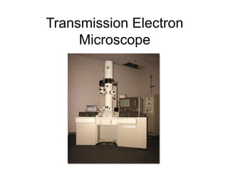
Transmission Electron
Microscope
General Uses
• Imaging of micro structural features at 1000 to 450000 X.
Resolution - ˂ 1 nm
• Qualitative and Quantitative elemental analysis
• Crystal structure and Orientation determination
• Lattice imaging of crystals with inter planar spacing
Applications
• High magnification characterization of the microstructure
of metals, ceramics, geologic materials, polymers and
biological materials
• Identification (Composition and Crystal structure) of
inorganic phases, precipitates and contaminants
Samples
• Solids – Metals, Ceramics, Minerals, Polymers,
biological etc.
• Size: ~ 5 µm thick, 3mm diam disk
• Preparation: Specimens must be sectioned and electro-
thinned or ion milled to produce regions that permit
transmission of the electron beam
• Powder samples are often dispersed on a thin carbon
substrate
Limitations
• Sample preparation is tedious and development of a suitable
procedure may take weeks
• Elemental microanalysis:
• Electron Diffraction:
Typical minimum size of the region
analyzed is 30 nm in diameter
Sensitivity- ~ 0.5 to 1 wt %
Accuracy of quantification – 5 to 15 %
Quantification possible for atomic
number ≥ 11
Minimum size of region analyzed : ~ 30 nm
Crystal structure identification is limited to phases or compounds
tabulated in powder difraction file
Introduction
• It is unique among materials characterization
techniques because of simultaneous
examination of micro-structural features through
high resolution imaging, chemical and
crystallographic information from small regions
of the specimen
Principles
• Formation of diffraction patterns and images in
TEM : Kinematic theory of electron diffraction
Instrumentation
• Electron Optics:
• Electron Beam Specimen Interaction
• Signal Detectors
Electron Guns
Electromagnetic Lenses
Elastic Scattering
Inelastic scattering
Electron scattering volume
2q ≈ sin 2q = R/L
l = 2d sin q ≈ d (2q)
R/L = l/d
Rd = lL
L is "camera length"
lL is "camera constant"
image plane
specimen
λ = wavelength of electrons ( 0.0037 nm and 0.0025 for 100 and 200 keV electrons
respectively
d = interplanar spacing for the family of diffracting planes
Θ= diffracting angle
Rules for Diffraction
• The diffraction of atomic plane is a function of
crystal structure.
• All planes can diffract in simple (Bravais) lattice.
• Only planes in which h and k (of the Miller
indices) are both odd or even can diffract in a
base-centered lattice
• Only planes in which (h+k+l) is even can diffract in
body-centered Bravais lattice.
• Only planes in which h, k and l are all even or odd
can diffract in a face-centered Bravais lattice.
Selected area diffraction patern (SADP)
• The selected-area aperture is used to limit the
area of the specimen for diffraction.
• The minimum area from which SADP is
generated is ~0.5 μm diameter.
• Three types of electron diffraction patterns
can be generated:
– Ring pattern
– Spot pattern
– Kikuchi line pattern
Diffraction
Get pattern of spots around transmitted beam from one grain (crystal)
Diffraction
Symmetry of diffraction pattern reflects
symmetry of crystal around beam direction
Why does 3-fold diffraction pattern look hexagonal?
[111] in cubic [001] in hexagonal
Example:
6-fold in hexagonal, 3-fold in cubic
Diffraction
Note: all diffraction patterns
are centrosymmetric,
even crystal structure is not
centrosymmetric (Friedel's
law)
Some 0-level patterns thus
exhibit higher rotational
symmetry than structure has
P cubic reciprocal lattice
layers along [111] direction
0-level
l = +1 level
l = -1 level
Diffraction
Cr23C6 - F cubic
a = 10.659 Å
Ni2AlTi - P cubic
a = 2.92 Å
Indexing electron diffraction patterns
Measure R-values for at least 3 reflections
Indexing electron diffraction patterns
Index other reflections by vector sums, differences
Next find zone axis from cross product of any two (hkl)s
(202) x (220) ——> [444] ——> [111]
Indexing electron diffraction patterns
Find crystal system, lattice parameters, index pattern, find zone axis
ACTF!!! Note symmetry - if cubic, what direction
has this symmetry (mm2)?
Reciprocal lattice unit cell
for cubic lattice is a cube
Polycrystalline regions
polycrystalline BaTiO3
spotty Debye rings
Indexing electron diffraction patterns - polycrystalline regions
Same as X-rays – smallest ring - lowest q - largest d
Hafnium (铪)
Indexing electron diffraction patterns - comments
Helps to have some idea what phases present
d-values not as precise as those from X-ray data
Systematic absences for lattice centering and other translational
symmetry same as for X-rays
Intensity information difficult to interpret
Sources of contrast
Diffraction contrast - some grains diffract more strongly than others;
defects may affect diffraction
Mass-thickness contrast - absorption/
scattering. Thicker areas or mat'ls w/
higher Z are dark
Bright field imaging
Only main beam is used. Aperture in back focal plane blocks diffracted
beams
Image contrast mainly due to subtraction of intensity from the main beam
by diffraction
Bright field imaging
Only main beam is used. Aperture in back focal plane blocks diffracted
beams
Image contrast mainly due to subtraction of intensity from the main beam
by diffraction
Bright field imaging
Only main beam is used. Aperture in back focal plane blocks diffracted
beams
Image contrast mainly due to subtraction of intensity from the main beam
by diffraction
Bright field imaging
Only main beam is used. Aperture in back focal plane blocks diffracted
beams
Image contrast mainly due to subtraction of intensity from the main beam
by diffraction
What else is in the image?
Many artifacts
surface films
local contamination
differential thinning
others
Also get changes in image because of
annealing due to heating by beam
Dark field imaging
Instead of main
beam, use a
diffracted beam
Move aperture to
diffracted beam or
tilt incident beam
Dark field imaging
Instead of main beam, use a diffracted beam
Move aperture to diffracted beam or tilt incident beam
strain field contrast
Dark field imaging
Instead of main beam, use a diffracted beam
Move aperture to diffracted beam or tilt incident beam
Lattice imaging
Use many diffracted beams
Slightly off-focus
Need very thin specimen region
Need precise specimen alignment
See channels through foil
Channels may be light or dark in image
Usually do image simulation to
determine features of structure
Examples
M23X6 (figure at top
left).
L21 type b'-Ni2AlTi
(figure at top center).
L12 type twinned g'-
Ni3Al (figure at bottom
center).
L10 type twinned NiAl
martensite (figure at
bottom right).

Transmission Electron Microscope_Lecture1.pptx

  • 1.
  • 2.
    General Uses • Imagingof micro structural features at 1000 to 450000 X. Resolution - ˂ 1 nm • Qualitative and Quantitative elemental analysis • Crystal structure and Orientation determination • Lattice imaging of crystals with inter planar spacing
  • 3.
    Applications • High magnificationcharacterization of the microstructure of metals, ceramics, geologic materials, polymers and biological materials • Identification (Composition and Crystal structure) of inorganic phases, precipitates and contaminants
  • 4.
    Samples • Solids –Metals, Ceramics, Minerals, Polymers, biological etc. • Size: ~ 5 µm thick, 3mm diam disk • Preparation: Specimens must be sectioned and electro- thinned or ion milled to produce regions that permit transmission of the electron beam • Powder samples are often dispersed on a thin carbon substrate
  • 5.
    Limitations • Sample preparationis tedious and development of a suitable procedure may take weeks • Elemental microanalysis: • Electron Diffraction: Typical minimum size of the region analyzed is 30 nm in diameter Sensitivity- ~ 0.5 to 1 wt % Accuracy of quantification – 5 to 15 % Quantification possible for atomic number ≥ 11 Minimum size of region analyzed : ~ 30 nm Crystal structure identification is limited to phases or compounds tabulated in powder difraction file
  • 6.
    Introduction • It isunique among materials characterization techniques because of simultaneous examination of micro-structural features through high resolution imaging, chemical and crystallographic information from small regions of the specimen
  • 7.
    Principles • Formation ofdiffraction patterns and images in TEM : Kinematic theory of electron diffraction
  • 8.
    Instrumentation • Electron Optics: •Electron Beam Specimen Interaction • Signal Detectors Electron Guns Electromagnetic Lenses Elastic Scattering Inelastic scattering Electron scattering volume
  • 11.
    2q ≈ sin2q = R/L l = 2d sin q ≈ d (2q) R/L = l/d Rd = lL L is "camera length" lL is "camera constant" image plane specimen λ = wavelength of electrons ( 0.0037 nm and 0.0025 for 100 and 200 keV electrons respectively d = interplanar spacing for the family of diffracting planes Θ= diffracting angle
  • 12.
    Rules for Diffraction •The diffraction of atomic plane is a function of crystal structure. • All planes can diffract in simple (Bravais) lattice. • Only planes in which h and k (of the Miller indices) are both odd or even can diffract in a base-centered lattice • Only planes in which (h+k+l) is even can diffract in body-centered Bravais lattice. • Only planes in which h, k and l are all even or odd can diffract in a face-centered Bravais lattice.
  • 13.
    Selected area diffractionpatern (SADP) • The selected-area aperture is used to limit the area of the specimen for diffraction. • The minimum area from which SADP is generated is ~0.5 μm diameter. • Three types of electron diffraction patterns can be generated: – Ring pattern – Spot pattern – Kikuchi line pattern
  • 14.
    Diffraction Get pattern ofspots around transmitted beam from one grain (crystal)
  • 15.
    Diffraction Symmetry of diffractionpattern reflects symmetry of crystal around beam direction Why does 3-fold diffraction pattern look hexagonal? [111] in cubic [001] in hexagonal Example: 6-fold in hexagonal, 3-fold in cubic
  • 16.
    Diffraction Note: all diffractionpatterns are centrosymmetric, even crystal structure is not centrosymmetric (Friedel's law) Some 0-level patterns thus exhibit higher rotational symmetry than structure has P cubic reciprocal lattice layers along [111] direction 0-level l = +1 level l = -1 level
  • 17.
    Diffraction Cr23C6 - Fcubic a = 10.659 Å Ni2AlTi - P cubic a = 2.92 Å
  • 18.
    Indexing electron diffractionpatterns Measure R-values for at least 3 reflections
  • 19.
  • 20.
    Indexing electron diffractionpatterns Index other reflections by vector sums, differences Next find zone axis from cross product of any two (hkl)s (202) x (220) ——> [444] ——> [111]
  • 21.
    Indexing electron diffractionpatterns Find crystal system, lattice parameters, index pattern, find zone axis ACTF!!! Note symmetry - if cubic, what direction has this symmetry (mm2)? Reciprocal lattice unit cell for cubic lattice is a cube
  • 22.
  • 23.
    Indexing electron diffractionpatterns - polycrystalline regions Same as X-rays – smallest ring - lowest q - largest d Hafnium (铪)
  • 24.
    Indexing electron diffractionpatterns - comments Helps to have some idea what phases present d-values not as precise as those from X-ray data Systematic absences for lattice centering and other translational symmetry same as for X-rays Intensity information difficult to interpret
  • 25.
    Sources of contrast Diffractioncontrast - some grains diffract more strongly than others; defects may affect diffraction Mass-thickness contrast - absorption/ scattering. Thicker areas or mat'ls w/ higher Z are dark
  • 26.
    Bright field imaging Onlymain beam is used. Aperture in back focal plane blocks diffracted beams Image contrast mainly due to subtraction of intensity from the main beam by diffraction
  • 27.
    Bright field imaging Onlymain beam is used. Aperture in back focal plane blocks diffracted beams Image contrast mainly due to subtraction of intensity from the main beam by diffraction
  • 28.
    Bright field imaging Onlymain beam is used. Aperture in back focal plane blocks diffracted beams Image contrast mainly due to subtraction of intensity from the main beam by diffraction
  • 29.
    Bright field imaging Onlymain beam is used. Aperture in back focal plane blocks diffracted beams Image contrast mainly due to subtraction of intensity from the main beam by diffraction
  • 30.
    What else isin the image? Many artifacts surface films local contamination differential thinning others Also get changes in image because of annealing due to heating by beam
  • 31.
    Dark field imaging Insteadof main beam, use a diffracted beam Move aperture to diffracted beam or tilt incident beam
  • 32.
    Dark field imaging Insteadof main beam, use a diffracted beam Move aperture to diffracted beam or tilt incident beam strain field contrast
  • 33.
    Dark field imaging Insteadof main beam, use a diffracted beam Move aperture to diffracted beam or tilt incident beam
  • 34.
    Lattice imaging Use manydiffracted beams Slightly off-focus Need very thin specimen region Need precise specimen alignment See channels through foil Channels may be light or dark in image Usually do image simulation to determine features of structure
  • 35.
    Examples M23X6 (figure attop left). L21 type b'-Ni2AlTi (figure at top center). L12 type twinned g'- Ni3Al (figure at bottom center). L10 type twinned NiAl martensite (figure at bottom right).