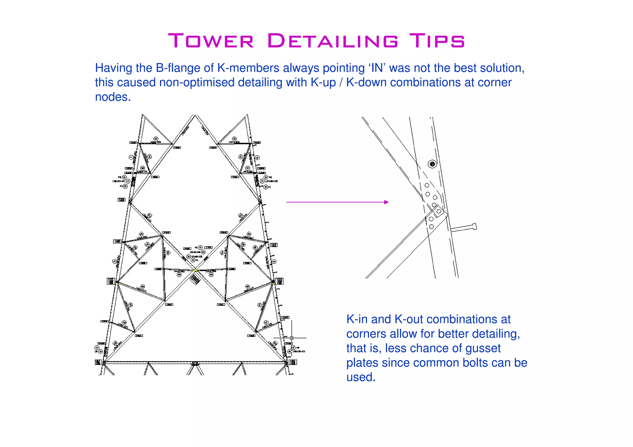
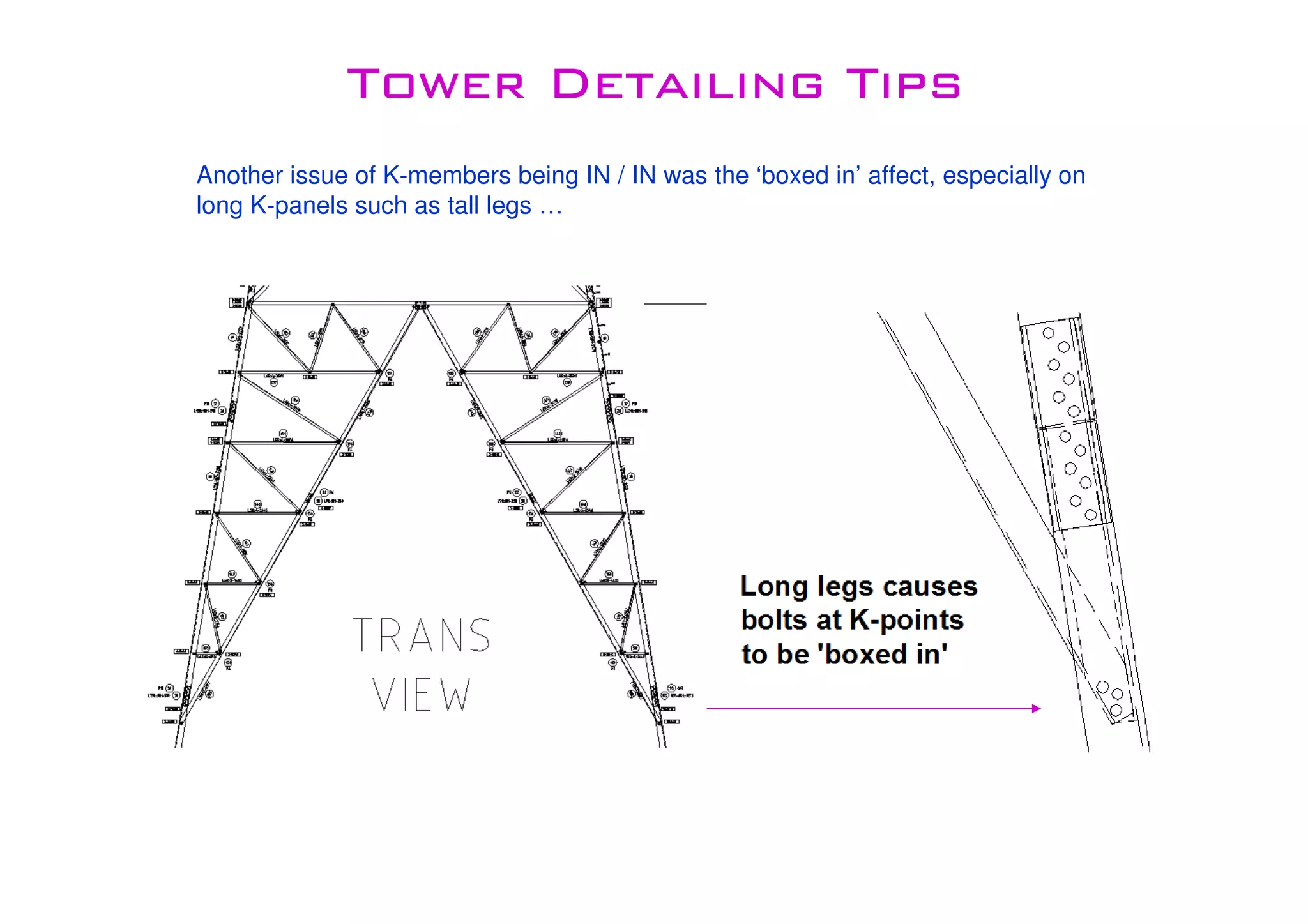
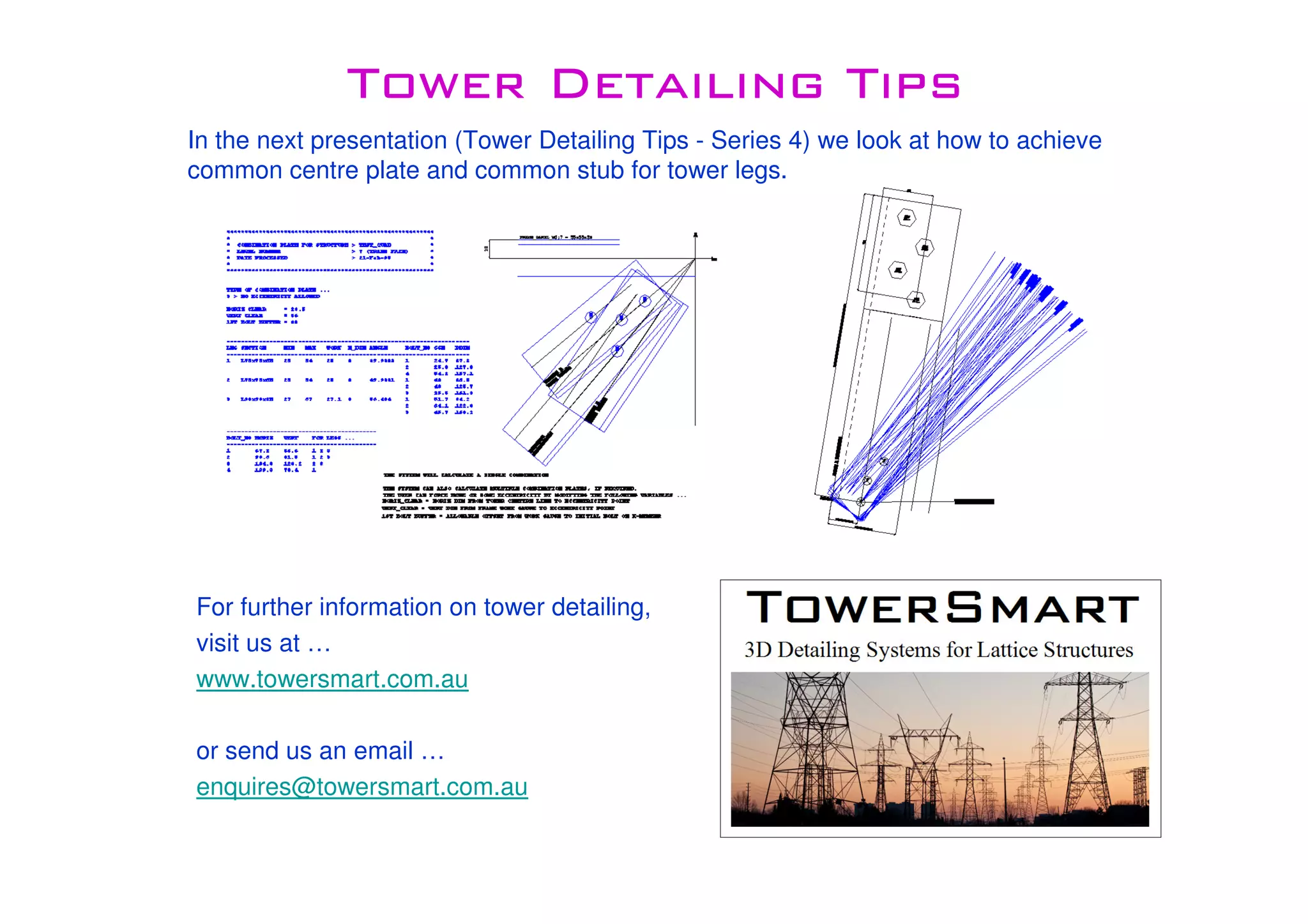
TowerSmartTowerSmartTowerSmartTowerSmart
Tower Detailing TipsTower Detailing TipsTower Detailing TipsTower Detailing Tips
Series 3Series 3Series 3Series 3
Tower Detailing TipsTower Detailing TipsTower Detailing TipsTower Detailing Tips
During the 1970’s, the company I began my career with decided to try a better way
of detailing internal bracings (also known as hip bracing). The traditional method
was to connect the hip bracing to the B-flange of K-members, what was proposed
by my boss at the time (Lino Pozzobon) was to connect the hips to the A-flange.
Below is a cross sectional plan view of a corner leg showing the two methods.
The main issue with connecting to the B-flange was that the main K members needed
to be IN-IN (B-flanges facing towards centre of tower) to allow better detailing.
Tower Detailing TipsTower Detailing TipsTower Detailing TipsTower Detailing Tips
Having the B-flange of K-members always pointing ‘IN’ was not the best solution,
this caused non-optimised detailing with K-up / K-down combinations at corner
nodes.
K-in and K-out combinations at
corners allow for better detailing,
that is, less chance of gusset
plates since common bolts can be
used.
Tower Detailing TipsTower Detailing TipsTower Detailing TipsTower Detailing Tips
Another issue of K-members being IN / IN was the ‘boxed in’ affect, especially on
long K-panels such as tall legs …
Tower Detailing TipsTower Detailing TipsTower Detailing TipsTower Detailing Tips
At times the K-member IN / IN rule was disregarded to offer better detailing on the
corner nodes, but this just created problems in other areas …
Tower Detailing TipsTower Detailing TipsTower Detailing TipsTower Detailing Tips
When the A-flange hip connection method was first introduced, many preliminary
tests were carried out and it was determined that the A-flange method was superior
and contained less eccentricities than B-flange connections.
The main benefit of A-flange connection is that it does not rely on the orientation of
K-members, the plane of the hip face stays the same. It also reduces the total
number of bolts required.
Since then nearly all transmission line and radio towers were detailed and
successfully tested using the A-flange method. It is a proven detailing connection
which has been locally and internationally adopted.
Tower Detailing TipsTower Detailing TipsTower Detailing TipsTower Detailing Tips
Below is a detailed example of hip plate connection to A-flange of K-member …
View
Looking
thru
K-member
View
at Back
View
at
Front
Tower Detailing TipsTower Detailing TipsTower Detailing TipsTower Detailing Tips
For further information on tower detailing,
visit us at …
www.towersmart.com.au
or send us an email …
enquires@towersmart.com.au
In the next presentation (Tower Detailing Tips - Series 4) we look at how to achieve
common centre plate and common stub for tower legs.

Tower smart tower_detailing_tips_series_3

  • 1.
    TowerSmartTowerSmartTowerSmartTowerSmart Tower Detailing TipsTowerDetailing TipsTower Detailing TipsTower Detailing Tips Series 3Series 3Series 3Series 3
  • 2.
    Tower Detailing TipsTowerDetailing TipsTower Detailing TipsTower Detailing Tips During the 1970’s, the company I began my career with decided to try a better way of detailing internal bracings (also known as hip bracing). The traditional method was to connect the hip bracing to the B-flange of K-members, what was proposed by my boss at the time (Lino Pozzobon) was to connect the hips to the A-flange. Below is a cross sectional plan view of a corner leg showing the two methods. The main issue with connecting to the B-flange was that the main K members needed to be IN-IN (B-flanges facing towards centre of tower) to allow better detailing.
  • 3.
    Tower Detailing TipsTowerDetailing TipsTower Detailing TipsTower Detailing Tips Having the B-flange of K-members always pointing ‘IN’ was not the best solution, this caused non-optimised detailing with K-up / K-down combinations at corner nodes. K-in and K-out combinations at corners allow for better detailing, that is, less chance of gusset plates since common bolts can be used.
  • 4.
    Tower Detailing TipsTowerDetailing TipsTower Detailing TipsTower Detailing Tips Another issue of K-members being IN / IN was the ‘boxed in’ affect, especially on long K-panels such as tall legs …
  • 5.
    Tower Detailing TipsTowerDetailing TipsTower Detailing TipsTower Detailing Tips At times the K-member IN / IN rule was disregarded to offer better detailing on the corner nodes, but this just created problems in other areas …
  • 6.
    Tower Detailing TipsTowerDetailing TipsTower Detailing TipsTower Detailing Tips When the A-flange hip connection method was first introduced, many preliminary tests were carried out and it was determined that the A-flange method was superior and contained less eccentricities than B-flange connections. The main benefit of A-flange connection is that it does not rely on the orientation of K-members, the plane of the hip face stays the same. It also reduces the total number of bolts required. Since then nearly all transmission line and radio towers were detailed and successfully tested using the A-flange method. It is a proven detailing connection which has been locally and internationally adopted.
  • 7.
    Tower Detailing TipsTowerDetailing TipsTower Detailing TipsTower Detailing Tips Below is a detailed example of hip plate connection to A-flange of K-member … View Looking thru K-member View at Back View at Front
  • 8.
    Tower Detailing TipsTowerDetailing TipsTower Detailing TipsTower Detailing Tips For further information on tower detailing, visit us at … www.towersmart.com.au or send us an email … enquires@towersmart.com.au In the next presentation (Tower Detailing Tips - Series 4) we look at how to achieve common centre plate and common stub for tower legs.