To study and draw the valve timings diagram Four-Stroke, Single-Cylinder Diesel Engine.
•Download as DOCX, PDF•
0 likes•900 views

To study and draw the valve timings diagram Four-Stroke, Single-Cylinder Diesel Engine.

Recommended
More Related Content
What's hot
What's hot (20)
Similar to To study and draw the valve timings diagram Four-Stroke, Single-Cylinder Diesel Engine.
Similar to To study and draw the valve timings diagram Four-Stroke, Single-Cylinder Diesel Engine. (20)
More from Salman Jailani
More from Salman Jailani (20)
Recently uploaded
Recently uploaded (20)
To study and draw the valve timings diagram Four-Stroke, Single-Cylinder Diesel Engine.
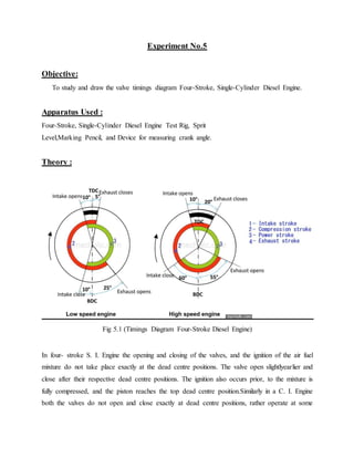
- 1. Experiment No.5 Objective: To study and draw the valve timings diagram Four-Stroke, Single-Cylinder Diesel Engine. Apparatus Used : Four-Stroke, Single-Cylinder Diesel Engine Test Rig, Sprit Level,Marking Pencil, and Device for measuring crank angle. Theory : Fig 5.1 (Timings Diagram Four-Stroke Diesel Engine) In four- stroke S. I. Engine the opening and closing of the valves, and the ignition of the air fuel mixture do not take place exactly at the dead centre positions. The valve open slightlyearlier and close after their respective dead centre positions. The ignition also occurs prior, to the mixture is fully compressed, and the piston reaches the top dead centre position.Similarly in a C. I. Engine both the valves do not open and close exactly at dead centre positions, rather operate at some
- 2. degree on either side in terms of the crank angles from the dead centre positions. The injection of the fuel is also timed to occur earlier. Procedure: 1. Fix a plate on the body of the Engine touching the flywheel. 2. Mark the positions of the both the dead centers on the flywheel with the reference to the fixed plate. TDC and BDC in case of vertical Engines, IDC and ODC in case of horizontal Engines. 3. Mark on the flywheel when the inlet and exhaust valves open and close as the 4. flywheel is rotated slowly.Measure the valves (Tappet) Clearance. 5. Mark the spark ignition timing in case of petrol Engine and fuel injection timing in case of Diesel Engine. 6. Measure the angles of the various events and plot the valve timing diagram.