SlideShare a Scribd company logo
1 of 28
Unit 2
Introduction to IC Engines and Electric Vehicles
Syllabus:
IC Engine:
• Basic definition of engine and Components,
• Construction and Working of Two stroke and four stroke SI & CI engine,
• Merits and demerits,
• Scavenging process;
• Difference between two-stroke and four stroke IC engines and SI and CI Engines.
Electric vehicles and hybrid vehicles:
• Components of an EV, EV batteries,
• Chargers, drives, transmission and power devices.
• Advantages and disadvantages of EVs.
• Hybrid electric vehicles, HEV drive train components, advantages of HV.
HEAT ENGINE
• It is a device which converts heat energy into mechanical energy.
• The heat is obtained from the combustion of fuel which may be coal, petrol, diesel and some
gases.
Heat engine may be classified into two main categories:-
1. External combustion engine
2. Internal combustion engine.
External combustion engine:
• In this engine, the products of combustion of air and fuel transfer
heat to a second fluid which is the working fluid of the cycle.
Examples:
• In the steam engine or a steam turbine plant.
• The heat engine, in which the combustion takes place inside the cylinder and the
heat energy of the flue gas is converted into mechanical energy, is known as
Internal Combustion Engine (I.C. Engine).
• Petrol & Diesel engines are examples of internal combustion engine, where the
working fluid is a mixture of air and fuel
Internal combustion engine
Comparison between external combustion engine and internal
combustion engine
External combustion engine Internal combustion engine
Combustion of air-fuel is outside the engine
cylinder
Combustion of air-fuel is inside the engine
cylinder
The engines are running smoothly and silently
due to outside combustion
Very noisy operated engine
Working pressure and temperature inside the
engine cylinder is low; hence ordinary
alloys are used for the manufacture of engine
Working pressure and temperature inside the
engine cylinder is very much high; hence
special alloys are used
Lower efficiency about 15-20% Higher efficiency about 35-40%
High starting torque IC engines are not self-starting
It can use cheaper fuels including solid fuels
High grade fuels are used with proper
filtration
Components of an I.C. Engine
Cylinder:
• It is a hollow cylindrical structure closed at one end with
the cylinder head.
• The combustion of the fuel takes place inside the
cylinder.
• This is known as the heart of the engine.
Cylinder Head:
• It covers one end of the cylinder and consists of
valves/ports and spark plug/injector.
Piston:
• It is a cylindrical component which is fitted perfectly
inside the cylinder providing a gas-tight space with the
piston rings and the lubricant.
• The main function of the piston is to transfer the power
produced by combustion of the fuel to the crankshaft.
Piston Rings:
• The outer periphery of the piston is provided with several
grooves into which piston rings are fitted.
• The function of the piston ring is to compress the air or air-fuel
mixture and collect the surplus lubricating oil on the liner
surface
Connecting Rod:
• It connects the piston and the crankshaft.
• One end, called the small end, is connected to the gudgeon
pin located in the piston and the other end, called big end, is
connected to crank pin.
• The function of the connecting rod is to transfer the
reciprocating motion of the piston into rotary motion of the
crankshaft.
Crankshaft:
It is principal rotating part of the engine which controls the sequence of reciprocating motion of the
pistons.
Valves:
Normally, the two valves are used for each cylinder, which may be of mushroom shaped poppet type.
Spark Plug:
• In an S.I engine, a spark plug is located near the top of the cylinder and initiates the
combustion of the fuel.
Crankcase:
• It consists of a cylinder, piston, and crankshaft. It helps in lubrication of different parts of the
engine.
Flywheel:
• It is a heavy wheel mounted on the crankshaft to minimize the cyclic variations in speed. It
absorbs the energy during the power stroke and releases it during the non-power stroke.
Crankshaft:
• It is principal rotating part of the engine which controls the sequence of reciprocating motion of
the pistons. It consists of several bearings and crank pins.
Carburetor: Carburetor is a device which is used to control the fuel qualitatively in an S.I engine.
Fuel Pump and Injector Unit:
• This unit is used in C.I. engines (nowadays injection system is also used in S.I. engine as multi-
point fuel injection, MPFI).
• Its function is to supply the fuel to injector under pressure which consists of one or more
orifices through which the fuel is sprayed into the cylinder.
Terminology used in IC engine:
A. Cylinder Bore (d):
• The nominal inner diameter of a cylinder is called a cylinder bore which is designated by an English
letter ‘d’ and expressed in millimeter (mm).
B. Piston Area (A):
• The area of the inner diameter of a cylinder is known as piston area. It is measured in terms of a square
centimeter (cm2) or square millimeter (mm2).
C. Stroke (L):
• The axial distance for which a piston moves inside a cylinder in one stroke is known as stroke or stroke
length which is designated by an English letter ‘L’ and measured in terms of a millimeter (mm).
D. Dead Centers:
• The positions of the piston, at the moments when the direction of the piston motion is reversed are
known as dead centers.
• There are two dead centers—Top dead center (TDC) and Bottom dead center (BDC).
• The farthest position of the piston head from the crankshaft is known as TDC and nearest position of the
piston head from the crankshaft is known as BDC
E. Displacement/Stroke/Swept Volume (Vs):
• The nominal volume swept by the working piston when traveling from one dead center to the other is
called the displacement volume. It is expressed in terms of a cubic centimeter (cc)
F. Clearance Volume (Vc):
• The nominal volume of the combustion chamber above the piston when it is at the at the TDC is known
as clearance volume (Vc) and is expressed in cc.
G. Compression Ratio (rv):
• It is the ratio of the total cylinder volume when the piston is at BDC to the clearance volume.
Classification of I.C. engines
There are several bases for classification of I.C. Engines, some of the important bases can be
explained as:
• Number of strokes per cycle
• Nature of thermodynamic cycle
• Ignition systems
• Fuel used
• Arrangement of cylinder
• Cooling systems
• Fuel supply systems
Working principle of I.C. engines
• I.C. Engines can be classified as four-stroke engines (4S) and two-stroke engines (2s).
• In four-stroke engines, the thermodynamic cycle is completed in four strokes of the piston or two
revolutions of the crankshaft whereas.
• In two-stroke engines, the thermodynamic cycle is completed in two strokes of the piston or one
revolution of the crankshaft.
1. Four-stroke Spark Ignition (S.I.) Engine
• In this engine, the cycle of operations is completed in 4-strokes of the piston or two revolutions of the
crankshaft.
• During the 4-strokes, there are four processes to be completed, viz.,
• 1. Suction stroke, 2. Compression stroke, 3. Combustion or power stroke , 4. Exhaust stroke.
• Each stroke consists of 180° rotation of he crankshaft and hence a 4-strokes cycle is completed in two
revolutions of the crankshaft.
Suction Stroke (0-1):
• It starts when the piston is at TDC and about to move
downward, the inlet valve is open, and the exhaust
valve is closed.
• Due to suction created by the piston movement
towards BDC, air-fuel mixture enters into the
cylinder, and the suction ends when the piston reaches
the BDC.
Compression Stroke (1-2):
• At the end of the suction stroke, the inlet valve is closed and
the piston moves towards TDC.
• In this stroke, both the valves, inlet and exhaust are closed;
compression of the air-fuel mixture filled in the cylinder
starts from BDC and ends at TDC.
• At the end of compression and at constant volume (2-3),
sparking starts at the spark plug and instantaneously burning
takes place in the compressed air-fuel
mixture.
• Pressure and temperature are increased to the maximum
limit.
Power Stroke (3-4):
• The high pressure developed due to combustion of fuel forces the
piston towards BDC.
• The power is transferred to the crankshaft.
• Pressure and temperature decrease during the stroke.
• In this stroke, both the valves are closed.
Exhaust Stroke (4-1):
• At the end of expansion or power stroke, the exhaust valve opens
and the inlet valve remains closed.
• Piston moves towards TDC and exhaust gas is forced to escape into
the atmosphere through the exhaust valve.
P-V Diagram for Otto Cycle
Four-stroke Compression Ignition (C.I.) Engine
• The four-stroke compression ignition (C.I. Engine) operates at a much higher compression ratio.
• The compression ratio of S.I. Engine varies from 6 to 10 whereas in C.I. Engines it ranges
from 16 to 20..
• In this engine, a fuel pump and injector are used to inject the fuel at high pressure.
• The ignition system of the C.I. Engine is completely different from S.I. engine as no spark plug
and carburetor are required.
Suction Stroke:
• In this stroke, the piston moves from TDC to BDC and air is sucked alone as the
vacuum is created inside the cylinder by the piston movement.
• During suction inlet valve is open and exhaust valve remains closed.
Compression Stroke:
• Both the valves are closed during the stroke and air is compressed into the
clearance volume by the piston movement from BDC to TDC.
• At the end of compression at constant pressure fuel is injected.
• Due to high pressure and temperature, fuel starts to ignite automatically as
temperature
of the air is increased to the flash point of the fuel
Expansion or Power Stroke:
• Fuel injection starts nearly at the end of the compression stroke.
• Heat is assumed to have been added at constant pressure.
• After the injection of the fuel is completed (after cut-off) the combustion
products expand.
• Both valves remain closed during the expansion stroke.
Exhaust Stroke:
• The exhaust valve is open and the inlet valve is closed during the stroke.
• The movement of the piston from BDC to TDC pushes the product of
combustion and disposed into the atmosphere through the exhaust valve
P-V Diagram for Diesel Cycle
Two-stroke Spark Ignition Engine
• A two-stroke engine is a type of internal combustion engine that completes a power cycle with two
strokes of the piston during only one crankshaft revolution.
• The cycle is completed in two-stroke i.e., one revolution of the crankshaft.
The different parts are listed as follows:
•Piston: The piston moves by the forces generated by the combustion of the gasses.
•Crankshaft: It is connected to the pistons and converts the reciprocal motion of the pistons into the
rotational motion.
•Connecting Rod: It connects the piston head to the crankshaft.
•Inlet Port: It is the opening for fuel and air mixture to come inside the piston
chamber.
•Exhaust Port: It is the opening for the exhaust fumes which opens during the
downstroke.
•Spark Plug: Spark plug is the device inside the piston chamber that causes the
combustion of the fuel-air mixture.
(1) Upward stroke of the piston (Suction + compression)
• When the piston moves from BDC to TDC the inlet port opens and the fresh air-fuel mixture enters easily due to
less pressure inside the crankcase(cylinder).
• During this, the transfer port remains closed. But as soon as the piston reaches TDC, the air-fuel mixture which
already present in TDC compressed and the spark plug ignites the compressed fuel.
(2) Downward stroke or Power Stroke (Expansion + Exhaust)
• Due to high pressure in TDC, the piston moves from TDC to BDC.
• The Inlet port will be closed and the exhaust port will be open. Transfer port also opens.
• Now, the fresh air-fuel mixture moves upwards through the transfer port and the exhaust gases move outward.
• When the piston moves TDC to BDC pressure inside the crankcase increases, due to which fresh air-fuel mixture
comes above the piston through the transfer port and pushes the exhaust gases due to which exhaust gases exit
through the exhaust port.
Comparison Between Four-stroke and Two-stroke Engines
Four-stroke Engines Two-stroke Engines
1
One power stroke is obtained in two revolutions of the
crankshaft
One power stroke is obtained in one revolution of the
crankshaft
2
The power produced from same size engine is less
than two-stroke engine due to one power stroke
in two revolutions of the crankshaft.
he power produced from same size engine is more
than the four-stroke engine due to one power stroke
in each revolution of the crankshaft.
3
It consists of valves and valve actuating mechanism
such as cam, camshaft, rocker arm, spring, valve, and
valve seat.
It has ports in place of valves
4
It has a higher thermal efficiency due to complete
combustion of the fuel.
t has a lower thermal efficiency due to the partial
wastage of fuel through the exhaust port and
incomplete combustion.
5
Turning moment is not so uniform during all the four
strokes and hence, the heavier flywheel is
required.
Comparatively, turning moment is more uniform and
hence lighter flywheel can be employed.
Comparison Between S.I. and C.I. Engines
S.I. Engines C.I. Engines
1
It is based on Otto cycle or constant volume heat
addition and rejection cycle.
It is based on a Diesel cycle or constant pressure heat
addition and constant volume heat rejection
2
A high volatile and high self-ignition temperature
fuel, i.e., gasoline is used.
Comparatively low volatile and low self-ignition
temperature fuel, i.e., diesel is used
3 A carburetor is necessary to provide the mixture. A fuel pump and injector units are used.
4
For combustion of the charge, it requires an ignition
system with a spark plug in the combustion
chamber.
Autoignition occurs due to the high-temperature of air
resulting from high-compression.
5 Compression ratio ranges from 6 to 10. 6. Compression ratio ranges from 16 to 20.
6
A gaseous mixture of fuel and air is inducted during
the suction stroke.
Fuel is injected at high pressure at the end of
compression stroke.
Advantages of 2-Stroke Engine
1.More power per weight –They can produce more power compared to their weight than many
other engine types. This makes them ideal for lightweight, high-speed vehicles.
2.Simple mechanical design – Their design is straightforward, with fewer moving parts. This less
complex structure is easier to understand and work with, making them a favorite among DIY
enthusiasts.
3.Lower cost of production – When it comes to production, these engines are cheaper to make.
This is due to their simple structure, requiring fewer components and less assembly time.
4.No need for valve system – Valves do not require in two stroke engine. Without the need for
valves, the design and operation of these engines become even simpler.
5.Easier to maintain – Maintenance is also less with two-stroke engines.
Disadvantages of 2 Stroke Engine
• Burn more fuel – Two stroke engines tend to consume more fuel compared to their four-stroke
counterparts, leading to increased operational costs.
• Less efficient – They are less efficient as they generate power once every two strokes, which
can lead to wasted energy.
• High pollution levels – These engines are known to produce high pollution levels, as they
release more unburned fuel into the environment.
• Requires frequent maintenance – Frequent maintenance is needed for two-stroke engines due
to their design and operation, increasing upkeep time and costs.
• Shorter lifespan – Lastly, the lifespan of a two-stroke engine is generally shorter because of the
constant high-speed operation, causing quicker wear and tear.
Scavenging Process
• Scavenging is the process of removing exhaust gases from a cylinder and replacing them with
fresh air.
• This process is important for the combustion of fuel inside the engine cylinder.
Types of Scavenging in Engine
1. Crossflow Scavenging
2. Loop Scavenging
3. Uniflow scavenging
Crossflow Scavenging
• Crossflow cylinder heads are used by most modern 2-stroke engines, whereby the intake ports
are located on one side of the combustion chamber and the exhaust ports are on the other side.
• The momentum of the gases assists in scavenging during the 'overlap' phase (when the intake
and exhaust valves are simultaneously open).
Loop scavenging.
• In this method, the inlet and outlet ports are situated on the same side of the engine cylinder.
• The intake port is larger to accommodate a greater volume of charge, while the smaller exhaust
port.
• Highly effective at high engine speeds, less efficient at low speeds.
Uniflow scavenging
• Uniflow scavenging is a design in which the fresh intake charge and exhaust gases flow in the
same direction.
• In this method, the fresh charge, while entering from one side (or sometimes two sides) of the
engine cylinder pushes out the gases through the exit valve situated on the top of the cylinder.
• This requires that the intake and exhaust ports be at opposite ends of the cylinder.

More Related Content

Similar to Internal combution of Engine (two stroke and four stroke)

Similar to Internal combution of Engine (two stroke and four stroke) (20)

I c engines a study
I c engines a studyI c engines a study
I c engines a study
 
I.C ENGINE PPT
I.C ENGINE PPTI.C ENGINE PPT
I.C ENGINE PPT
 
Internal Combustion E Presentation PPt.pdf
Internal Combustion E Presentation PPt.pdfInternal Combustion E Presentation PPt.pdf
Internal Combustion E Presentation PPt.pdf
 
Fundamentals of Engine Technologies.pptx
Fundamentals of Engine Technologies.pptxFundamentals of Engine Technologies.pptx
Fundamentals of Engine Technologies.pptx
 
Part.pptx
Part.pptxPart.pptx
Part.pptx
 
Module 3a.pdf
Module 3a.pdfModule 3a.pdf
Module 3a.pdf
 
Internal combustion engine
Internal combustion engineInternal combustion engine
Internal combustion engine
 
IC Engine Otto and Diesel Cycle.pptx
IC Engine Otto and Diesel Cycle.pptxIC Engine Otto and Diesel Cycle.pptx
IC Engine Otto and Diesel Cycle.pptx
 
IC engine-1.pptx
IC engine-1.pptxIC engine-1.pptx
IC engine-1.pptx
 
I c enginen
I c enginenI c enginen
I c enginen
 
IC engine and Gas Turbine.pptx
IC engine and Gas Turbine.pptxIC engine and Gas Turbine.pptx
IC engine and Gas Turbine.pptx
 
Combustion cycle
Combustion cycleCombustion cycle
Combustion cycle
 
I.c. engines
I.c. enginesI.c. engines
I.c. engines
 
2s vs 4s stroke engines (mechanical)
2s vs 4s stroke engines (mechanical)2s vs 4s stroke engines (mechanical)
2s vs 4s stroke engines (mechanical)
 
IC ENGINES.pptx
IC ENGINES.pptxIC ENGINES.pptx
IC ENGINES.pptx
 
Ic engine introduction
Ic engine introductionIc engine introduction
Ic engine introduction
 
History of the diesel engine
History of the diesel engine History of the diesel engine
History of the diesel engine
 
Unit 2.2 thm
Unit 2.2 thmUnit 2.2 thm
Unit 2.2 thm
 
IC Engines- 2 stroke and 4 stroke
IC Engines- 2 stroke and 4 strokeIC Engines- 2 stroke and 4 stroke
IC Engines- 2 stroke and 4 stroke
 
Week 5
Week 5Week 5
Week 5
 

Recently uploaded

Sheet Pile Wall Design and Construction: A Practical Guide for Civil Engineer...
Sheet Pile Wall Design and Construction: A Practical Guide for Civil Engineer...Sheet Pile Wall Design and Construction: A Practical Guide for Civil Engineer...
Sheet Pile Wall Design and Construction: A Practical Guide for Civil Engineer...Dr.Costas Sachpazis
 
What are the advantages and disadvantages of membrane structures.pptx
What are the advantages and disadvantages of membrane structures.pptxWhat are the advantages and disadvantages of membrane structures.pptx
What are the advantages and disadvantages of membrane structures.pptxwendy cai
 
microprocessor 8085 and its interfacing
microprocessor 8085  and its interfacingmicroprocessor 8085  and its interfacing
microprocessor 8085 and its interfacingjaychoudhary37
 
Call Girls Delhi {Jodhpur} 9711199012 high profile service
Call Girls Delhi {Jodhpur} 9711199012 high profile serviceCall Girls Delhi {Jodhpur} 9711199012 high profile service
Call Girls Delhi {Jodhpur} 9711199012 high profile servicerehmti665
 
SPICE PARK APR2024 ( 6,793 SPICE Models )
SPICE PARK APR2024 ( 6,793 SPICE Models )SPICE PARK APR2024 ( 6,793 SPICE Models )
SPICE PARK APR2024 ( 6,793 SPICE Models )Tsuyoshi Horigome
 
ZXCTN 5804 / ZTE PTN / ZTE POTN / ZTE 5804 PTN / ZTE POTN 5804 ( 100/200 GE Z...
ZXCTN 5804 / ZTE PTN / ZTE POTN / ZTE 5804 PTN / ZTE POTN 5804 ( 100/200 GE Z...ZXCTN 5804 / ZTE PTN / ZTE POTN / ZTE 5804 PTN / ZTE POTN 5804 ( 100/200 GE Z...
ZXCTN 5804 / ZTE PTN / ZTE POTN / ZTE 5804 PTN / ZTE POTN 5804 ( 100/200 GE Z...ZTE
 
Application of Residue Theorem to evaluate real integrations.pptx
Application of Residue Theorem to evaluate real integrations.pptxApplication of Residue Theorem to evaluate real integrations.pptx
Application of Residue Theorem to evaluate real integrations.pptx959SahilShah
 
Artificial-Intelligence-in-Electronics (K).pptx
Artificial-Intelligence-in-Electronics (K).pptxArtificial-Intelligence-in-Electronics (K).pptx
Artificial-Intelligence-in-Electronics (K).pptxbritheesh05
 
Microscopic Analysis of Ceramic Materials.pptx
Microscopic Analysis of Ceramic Materials.pptxMicroscopic Analysis of Ceramic Materials.pptx
Microscopic Analysis of Ceramic Materials.pptxpurnimasatapathy1234
 
High Profile Call Girls Nagpur Isha Call 7001035870 Meet With Nagpur Escorts
High Profile Call Girls Nagpur Isha Call 7001035870 Meet With Nagpur EscortsHigh Profile Call Girls Nagpur Isha Call 7001035870 Meet With Nagpur Escorts
High Profile Call Girls Nagpur Isha Call 7001035870 Meet With Nagpur Escortsranjana rawat
 
Software and Systems Engineering Standards: Verification and Validation of Sy...
Software and Systems Engineering Standards: Verification and Validation of Sy...Software and Systems Engineering Standards: Verification and Validation of Sy...
Software and Systems Engineering Standards: Verification and Validation of Sy...VICTOR MAESTRE RAMIREZ
 
College Call Girls Nashik Nehal 7001305949 Independent Escort Service Nashik
College Call Girls Nashik Nehal 7001305949 Independent Escort Service NashikCollege Call Girls Nashik Nehal 7001305949 Independent Escort Service Nashik
College Call Girls Nashik Nehal 7001305949 Independent Escort Service NashikCall Girls in Nagpur High Profile
 
(ANVI) Koregaon Park Call Girls Just Call 7001035870 [ Cash on Delivery ] Pun...
(ANVI) Koregaon Park Call Girls Just Call 7001035870 [ Cash on Delivery ] Pun...(ANVI) Koregaon Park Call Girls Just Call 7001035870 [ Cash on Delivery ] Pun...
(ANVI) Koregaon Park Call Girls Just Call 7001035870 [ Cash on Delivery ] Pun...ranjana rawat
 
Internship report on mechanical engineering
Internship report on mechanical engineeringInternship report on mechanical engineering
Internship report on mechanical engineeringmalavadedarshan25
 
Call Girls Narol 7397865700 Independent Call Girls
Call Girls Narol 7397865700 Independent Call GirlsCall Girls Narol 7397865700 Independent Call Girls
Call Girls Narol 7397865700 Independent Call Girlsssuser7cb4ff
 
HARMONY IN THE HUMAN BEING - Unit-II UHV-2
HARMONY IN THE HUMAN BEING - Unit-II UHV-2HARMONY IN THE HUMAN BEING - Unit-II UHV-2
HARMONY IN THE HUMAN BEING - Unit-II UHV-2RajaP95
 

Recently uploaded (20)

Sheet Pile Wall Design and Construction: A Practical Guide for Civil Engineer...
Sheet Pile Wall Design and Construction: A Practical Guide for Civil Engineer...Sheet Pile Wall Design and Construction: A Practical Guide for Civil Engineer...
Sheet Pile Wall Design and Construction: A Practical Guide for Civil Engineer...
 
What are the advantages and disadvantages of membrane structures.pptx
What are the advantages and disadvantages of membrane structures.pptxWhat are the advantages and disadvantages of membrane structures.pptx
What are the advantages and disadvantages of membrane structures.pptx
 
microprocessor 8085 and its interfacing
microprocessor 8085  and its interfacingmicroprocessor 8085  and its interfacing
microprocessor 8085 and its interfacing
 
9953056974 Call Girls In South Ex, Escorts (Delhi) NCR.pdf
9953056974 Call Girls In South Ex, Escorts (Delhi) NCR.pdf9953056974 Call Girls In South Ex, Escorts (Delhi) NCR.pdf
9953056974 Call Girls In South Ex, Escorts (Delhi) NCR.pdf
 
Call Girls Delhi {Jodhpur} 9711199012 high profile service
Call Girls Delhi {Jodhpur} 9711199012 high profile serviceCall Girls Delhi {Jodhpur} 9711199012 high profile service
Call Girls Delhi {Jodhpur} 9711199012 high profile service
 
🔝9953056974🔝!!-YOUNG call girls in Rajendra Nagar Escort rvice Shot 2000 nigh...
🔝9953056974🔝!!-YOUNG call girls in Rajendra Nagar Escort rvice Shot 2000 nigh...🔝9953056974🔝!!-YOUNG call girls in Rajendra Nagar Escort rvice Shot 2000 nigh...
🔝9953056974🔝!!-YOUNG call girls in Rajendra Nagar Escort rvice Shot 2000 nigh...
 
SPICE PARK APR2024 ( 6,793 SPICE Models )
SPICE PARK APR2024 ( 6,793 SPICE Models )SPICE PARK APR2024 ( 6,793 SPICE Models )
SPICE PARK APR2024 ( 6,793 SPICE Models )
 
ZXCTN 5804 / ZTE PTN / ZTE POTN / ZTE 5804 PTN / ZTE POTN 5804 ( 100/200 GE Z...
ZXCTN 5804 / ZTE PTN / ZTE POTN / ZTE 5804 PTN / ZTE POTN 5804 ( 100/200 GE Z...ZXCTN 5804 / ZTE PTN / ZTE POTN / ZTE 5804 PTN / ZTE POTN 5804 ( 100/200 GE Z...
ZXCTN 5804 / ZTE PTN / ZTE POTN / ZTE 5804 PTN / ZTE POTN 5804 ( 100/200 GE Z...
 
Call Us -/9953056974- Call Girls In Vikaspuri-/- Delhi NCR
Call Us -/9953056974- Call Girls In Vikaspuri-/- Delhi NCRCall Us -/9953056974- Call Girls In Vikaspuri-/- Delhi NCR
Call Us -/9953056974- Call Girls In Vikaspuri-/- Delhi NCR
 
Application of Residue Theorem to evaluate real integrations.pptx
Application of Residue Theorem to evaluate real integrations.pptxApplication of Residue Theorem to evaluate real integrations.pptx
Application of Residue Theorem to evaluate real integrations.pptx
 
young call girls in Rajiv Chowk🔝 9953056974 🔝 Delhi escort Service
young call girls in Rajiv Chowk🔝 9953056974 🔝 Delhi escort Serviceyoung call girls in Rajiv Chowk🔝 9953056974 🔝 Delhi escort Service
young call girls in Rajiv Chowk🔝 9953056974 🔝 Delhi escort Service
 
Artificial-Intelligence-in-Electronics (K).pptx
Artificial-Intelligence-in-Electronics (K).pptxArtificial-Intelligence-in-Electronics (K).pptx
Artificial-Intelligence-in-Electronics (K).pptx
 
Microscopic Analysis of Ceramic Materials.pptx
Microscopic Analysis of Ceramic Materials.pptxMicroscopic Analysis of Ceramic Materials.pptx
Microscopic Analysis of Ceramic Materials.pptx
 
High Profile Call Girls Nagpur Isha Call 7001035870 Meet With Nagpur Escorts
High Profile Call Girls Nagpur Isha Call 7001035870 Meet With Nagpur EscortsHigh Profile Call Girls Nagpur Isha Call 7001035870 Meet With Nagpur Escorts
High Profile Call Girls Nagpur Isha Call 7001035870 Meet With Nagpur Escorts
 
Software and Systems Engineering Standards: Verification and Validation of Sy...
Software and Systems Engineering Standards: Verification and Validation of Sy...Software and Systems Engineering Standards: Verification and Validation of Sy...
Software and Systems Engineering Standards: Verification and Validation of Sy...
 
College Call Girls Nashik Nehal 7001305949 Independent Escort Service Nashik
College Call Girls Nashik Nehal 7001305949 Independent Escort Service NashikCollege Call Girls Nashik Nehal 7001305949 Independent Escort Service Nashik
College Call Girls Nashik Nehal 7001305949 Independent Escort Service Nashik
 
(ANVI) Koregaon Park Call Girls Just Call 7001035870 [ Cash on Delivery ] Pun...
(ANVI) Koregaon Park Call Girls Just Call 7001035870 [ Cash on Delivery ] Pun...(ANVI) Koregaon Park Call Girls Just Call 7001035870 [ Cash on Delivery ] Pun...
(ANVI) Koregaon Park Call Girls Just Call 7001035870 [ Cash on Delivery ] Pun...
 
Internship report on mechanical engineering
Internship report on mechanical engineeringInternship report on mechanical engineering
Internship report on mechanical engineering
 
Call Girls Narol 7397865700 Independent Call Girls
Call Girls Narol 7397865700 Independent Call GirlsCall Girls Narol 7397865700 Independent Call Girls
Call Girls Narol 7397865700 Independent Call Girls
 
HARMONY IN THE HUMAN BEING - Unit-II UHV-2
HARMONY IN THE HUMAN BEING - Unit-II UHV-2HARMONY IN THE HUMAN BEING - Unit-II UHV-2
HARMONY IN THE HUMAN BEING - Unit-II UHV-2
 

Internal combution of Engine (two stroke and four stroke)

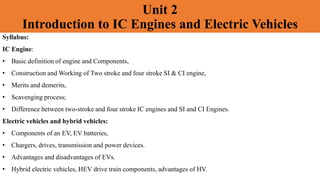
  • 1. Unit 2 Introduction to IC Engines and Electric Vehicles Syllabus: IC Engine: • Basic definition of engine and Components, • Construction and Working of Two stroke and four stroke SI & CI engine, • Merits and demerits, • Scavenging process; • Difference between two-stroke and four stroke IC engines and SI and CI Engines. Electric vehicles and hybrid vehicles: • Components of an EV, EV batteries, • Chargers, drives, transmission and power devices. • Advantages and disadvantages of EVs. • Hybrid electric vehicles, HEV drive train components, advantages of HV.
  • 2. HEAT ENGINE • It is a device which converts heat energy into mechanical energy. • The heat is obtained from the combustion of fuel which may be coal, petrol, diesel and some gases. Heat engine may be classified into two main categories:- 1. External combustion engine 2. Internal combustion engine.
  • 3. External combustion engine: • In this engine, the products of combustion of air and fuel transfer heat to a second fluid which is the working fluid of the cycle. Examples: • In the steam engine or a steam turbine plant. • The heat engine, in which the combustion takes place inside the cylinder and the heat energy of the flue gas is converted into mechanical energy, is known as Internal Combustion Engine (I.C. Engine). • Petrol & Diesel engines are examples of internal combustion engine, where the working fluid is a mixture of air and fuel Internal combustion engine
  • 4. Comparison between external combustion engine and internal combustion engine External combustion engine Internal combustion engine Combustion of air-fuel is outside the engine cylinder Combustion of air-fuel is inside the engine cylinder The engines are running smoothly and silently due to outside combustion Very noisy operated engine Working pressure and temperature inside the engine cylinder is low; hence ordinary alloys are used for the manufacture of engine Working pressure and temperature inside the engine cylinder is very much high; hence special alloys are used Lower efficiency about 15-20% Higher efficiency about 35-40% High starting torque IC engines are not self-starting It can use cheaper fuels including solid fuels High grade fuels are used with proper filtration
  • 5. Components of an I.C. Engine Cylinder: • It is a hollow cylindrical structure closed at one end with the cylinder head. • The combustion of the fuel takes place inside the cylinder. • This is known as the heart of the engine. Cylinder Head: • It covers one end of the cylinder and consists of valves/ports and spark plug/injector. Piston: • It is a cylindrical component which is fitted perfectly inside the cylinder providing a gas-tight space with the piston rings and the lubricant. • The main function of the piston is to transfer the power produced by combustion of the fuel to the crankshaft.
  • 6. Piston Rings: • The outer periphery of the piston is provided with several grooves into which piston rings are fitted. • The function of the piston ring is to compress the air or air-fuel mixture and collect the surplus lubricating oil on the liner surface Connecting Rod: • It connects the piston and the crankshaft. • One end, called the small end, is connected to the gudgeon pin located in the piston and the other end, called big end, is connected to crank pin. • The function of the connecting rod is to transfer the reciprocating motion of the piston into rotary motion of the crankshaft. Crankshaft: It is principal rotating part of the engine which controls the sequence of reciprocating motion of the pistons. Valves: Normally, the two valves are used for each cylinder, which may be of mushroom shaped poppet type.
  • 7. Spark Plug: • In an S.I engine, a spark plug is located near the top of the cylinder and initiates the combustion of the fuel. Crankcase: • It consists of a cylinder, piston, and crankshaft. It helps in lubrication of different parts of the engine. Flywheel: • It is a heavy wheel mounted on the crankshaft to minimize the cyclic variations in speed. It absorbs the energy during the power stroke and releases it during the non-power stroke. Crankshaft: • It is principal rotating part of the engine which controls the sequence of reciprocating motion of the pistons. It consists of several bearings and crank pins. Carburetor: Carburetor is a device which is used to control the fuel qualitatively in an S.I engine. Fuel Pump and Injector Unit: • This unit is used in C.I. engines (nowadays injection system is also used in S.I. engine as multi- point fuel injection, MPFI). • Its function is to supply the fuel to injector under pressure which consists of one or more orifices through which the fuel is sprayed into the cylinder.
  • 8. Terminology used in IC engine: A. Cylinder Bore (d): • The nominal inner diameter of a cylinder is called a cylinder bore which is designated by an English letter ‘d’ and expressed in millimeter (mm). B. Piston Area (A): • The area of the inner diameter of a cylinder is known as piston area. It is measured in terms of a square centimeter (cm2) or square millimeter (mm2). C. Stroke (L): • The axial distance for which a piston moves inside a cylinder in one stroke is known as stroke or stroke length which is designated by an English letter ‘L’ and measured in terms of a millimeter (mm). D. Dead Centers: • The positions of the piston, at the moments when the direction of the piston motion is reversed are known as dead centers. • There are two dead centers—Top dead center (TDC) and Bottom dead center (BDC). • The farthest position of the piston head from the crankshaft is known as TDC and nearest position of the piston head from the crankshaft is known as BDC
  • 9.
  • 10. E. Displacement/Stroke/Swept Volume (Vs): • The nominal volume swept by the working piston when traveling from one dead center to the other is called the displacement volume. It is expressed in terms of a cubic centimeter (cc) F. Clearance Volume (Vc): • The nominal volume of the combustion chamber above the piston when it is at the at the TDC is known as clearance volume (Vc) and is expressed in cc. G. Compression Ratio (rv): • It is the ratio of the total cylinder volume when the piston is at BDC to the clearance volume.
  • 11. Classification of I.C. engines There are several bases for classification of I.C. Engines, some of the important bases can be explained as: • Number of strokes per cycle • Nature of thermodynamic cycle • Ignition systems • Fuel used • Arrangement of cylinder • Cooling systems • Fuel supply systems
  • 12. Working principle of I.C. engines • I.C. Engines can be classified as four-stroke engines (4S) and two-stroke engines (2s). • In four-stroke engines, the thermodynamic cycle is completed in four strokes of the piston or two revolutions of the crankshaft whereas. • In two-stroke engines, the thermodynamic cycle is completed in two strokes of the piston or one revolution of the crankshaft. 1. Four-stroke Spark Ignition (S.I.) Engine • In this engine, the cycle of operations is completed in 4-strokes of the piston or two revolutions of the crankshaft. • During the 4-strokes, there are four processes to be completed, viz., • 1. Suction stroke, 2. Compression stroke, 3. Combustion or power stroke , 4. Exhaust stroke. • Each stroke consists of 180° rotation of he crankshaft and hence a 4-strokes cycle is completed in two revolutions of the crankshaft.
  • 13. Suction Stroke (0-1): • It starts when the piston is at TDC and about to move downward, the inlet valve is open, and the exhaust valve is closed. • Due to suction created by the piston movement towards BDC, air-fuel mixture enters into the cylinder, and the suction ends when the piston reaches the BDC. Compression Stroke (1-2): • At the end of the suction stroke, the inlet valve is closed and the piston moves towards TDC. • In this stroke, both the valves, inlet and exhaust are closed; compression of the air-fuel mixture filled in the cylinder starts from BDC and ends at TDC. • At the end of compression and at constant volume (2-3), sparking starts at the spark plug and instantaneously burning takes place in the compressed air-fuel mixture. • Pressure and temperature are increased to the maximum limit.
  • 14. Power Stroke (3-4): • The high pressure developed due to combustion of fuel forces the piston towards BDC. • The power is transferred to the crankshaft. • Pressure and temperature decrease during the stroke. • In this stroke, both the valves are closed. Exhaust Stroke (4-1): • At the end of expansion or power stroke, the exhaust valve opens and the inlet valve remains closed. • Piston moves towards TDC and exhaust gas is forced to escape into the atmosphere through the exhaust valve.
  • 15. P-V Diagram for Otto Cycle
  • 16. Four-stroke Compression Ignition (C.I.) Engine • The four-stroke compression ignition (C.I. Engine) operates at a much higher compression ratio. • The compression ratio of S.I. Engine varies from 6 to 10 whereas in C.I. Engines it ranges from 16 to 20.. • In this engine, a fuel pump and injector are used to inject the fuel at high pressure. • The ignition system of the C.I. Engine is completely different from S.I. engine as no spark plug and carburetor are required.
  • 17. Suction Stroke: • In this stroke, the piston moves from TDC to BDC and air is sucked alone as the vacuum is created inside the cylinder by the piston movement. • During suction inlet valve is open and exhaust valve remains closed. Compression Stroke: • Both the valves are closed during the stroke and air is compressed into the clearance volume by the piston movement from BDC to TDC. • At the end of compression at constant pressure fuel is injected. • Due to high pressure and temperature, fuel starts to ignite automatically as temperature of the air is increased to the flash point of the fuel
  • 18. Expansion or Power Stroke: • Fuel injection starts nearly at the end of the compression stroke. • Heat is assumed to have been added at constant pressure. • After the injection of the fuel is completed (after cut-off) the combustion products expand. • Both valves remain closed during the expansion stroke. Exhaust Stroke: • The exhaust valve is open and the inlet valve is closed during the stroke. • The movement of the piston from BDC to TDC pushes the product of combustion and disposed into the atmosphere through the exhaust valve
  • 19. P-V Diagram for Diesel Cycle
  • 20. Two-stroke Spark Ignition Engine • A two-stroke engine is a type of internal combustion engine that completes a power cycle with two strokes of the piston during only one crankshaft revolution. • The cycle is completed in two-stroke i.e., one revolution of the crankshaft. The different parts are listed as follows: •Piston: The piston moves by the forces generated by the combustion of the gasses. •Crankshaft: It is connected to the pistons and converts the reciprocal motion of the pistons into the rotational motion. •Connecting Rod: It connects the piston head to the crankshaft. •Inlet Port: It is the opening for fuel and air mixture to come inside the piston chamber. •Exhaust Port: It is the opening for the exhaust fumes which opens during the downstroke. •Spark Plug: Spark plug is the device inside the piston chamber that causes the combustion of the fuel-air mixture.
  • 21.
  • 22. (1) Upward stroke of the piston (Suction + compression) • When the piston moves from BDC to TDC the inlet port opens and the fresh air-fuel mixture enters easily due to less pressure inside the crankcase(cylinder). • During this, the transfer port remains closed. But as soon as the piston reaches TDC, the air-fuel mixture which already present in TDC compressed and the spark plug ignites the compressed fuel. (2) Downward stroke or Power Stroke (Expansion + Exhaust) • Due to high pressure in TDC, the piston moves from TDC to BDC. • The Inlet port will be closed and the exhaust port will be open. Transfer port also opens. • Now, the fresh air-fuel mixture moves upwards through the transfer port and the exhaust gases move outward. • When the piston moves TDC to BDC pressure inside the crankcase increases, due to which fresh air-fuel mixture comes above the piston through the transfer port and pushes the exhaust gases due to which exhaust gases exit through the exhaust port.
  • 23. Comparison Between Four-stroke and Two-stroke Engines Four-stroke Engines Two-stroke Engines 1 One power stroke is obtained in two revolutions of the crankshaft One power stroke is obtained in one revolution of the crankshaft 2 The power produced from same size engine is less than two-stroke engine due to one power stroke in two revolutions of the crankshaft. he power produced from same size engine is more than the four-stroke engine due to one power stroke in each revolution of the crankshaft. 3 It consists of valves and valve actuating mechanism such as cam, camshaft, rocker arm, spring, valve, and valve seat. It has ports in place of valves 4 It has a higher thermal efficiency due to complete combustion of the fuel. t has a lower thermal efficiency due to the partial wastage of fuel through the exhaust port and incomplete combustion. 5 Turning moment is not so uniform during all the four strokes and hence, the heavier flywheel is required. Comparatively, turning moment is more uniform and hence lighter flywheel can be employed.
  • 24. Comparison Between S.I. and C.I. Engines S.I. Engines C.I. Engines 1 It is based on Otto cycle or constant volume heat addition and rejection cycle. It is based on a Diesel cycle or constant pressure heat addition and constant volume heat rejection 2 A high volatile and high self-ignition temperature fuel, i.e., gasoline is used. Comparatively low volatile and low self-ignition temperature fuel, i.e., diesel is used 3 A carburetor is necessary to provide the mixture. A fuel pump and injector units are used. 4 For combustion of the charge, it requires an ignition system with a spark plug in the combustion chamber. Autoignition occurs due to the high-temperature of air resulting from high-compression. 5 Compression ratio ranges from 6 to 10. 6. Compression ratio ranges from 16 to 20. 6 A gaseous mixture of fuel and air is inducted during the suction stroke. Fuel is injected at high pressure at the end of compression stroke.
  • 25. Advantages of 2-Stroke Engine 1.More power per weight –They can produce more power compared to their weight than many other engine types. This makes them ideal for lightweight, high-speed vehicles. 2.Simple mechanical design – Their design is straightforward, with fewer moving parts. This less complex structure is easier to understand and work with, making them a favorite among DIY enthusiasts. 3.Lower cost of production – When it comes to production, these engines are cheaper to make. This is due to their simple structure, requiring fewer components and less assembly time. 4.No need for valve system – Valves do not require in two stroke engine. Without the need for valves, the design and operation of these engines become even simpler. 5.Easier to maintain – Maintenance is also less with two-stroke engines.
  • 26. Disadvantages of 2 Stroke Engine • Burn more fuel – Two stroke engines tend to consume more fuel compared to their four-stroke counterparts, leading to increased operational costs. • Less efficient – They are less efficient as they generate power once every two strokes, which can lead to wasted energy. • High pollution levels – These engines are known to produce high pollution levels, as they release more unburned fuel into the environment. • Requires frequent maintenance – Frequent maintenance is needed for two-stroke engines due to their design and operation, increasing upkeep time and costs. • Shorter lifespan – Lastly, the lifespan of a two-stroke engine is generally shorter because of the constant high-speed operation, causing quicker wear and tear.
  • 27. Scavenging Process • Scavenging is the process of removing exhaust gases from a cylinder and replacing them with fresh air. • This process is important for the combustion of fuel inside the engine cylinder. Types of Scavenging in Engine 1. Crossflow Scavenging 2. Loop Scavenging 3. Uniflow scavenging
  • 28. Crossflow Scavenging • Crossflow cylinder heads are used by most modern 2-stroke engines, whereby the intake ports are located on one side of the combustion chamber and the exhaust ports are on the other side. • The momentum of the gases assists in scavenging during the 'overlap' phase (when the intake and exhaust valves are simultaneously open). Loop scavenging. • In this method, the inlet and outlet ports are situated on the same side of the engine cylinder. • The intake port is larger to accommodate a greater volume of charge, while the smaller exhaust port. • Highly effective at high engine speeds, less efficient at low speeds. Uniflow scavenging • Uniflow scavenging is a design in which the fresh intake charge and exhaust gases flow in the same direction. • In this method, the fresh charge, while entering from one side (or sometimes two sides) of the engine cylinder pushes out the gases through the exit valve situated on the top of the cylinder. • This requires that the intake and exhaust ports be at opposite ends of the cylinder.