Download to read offline


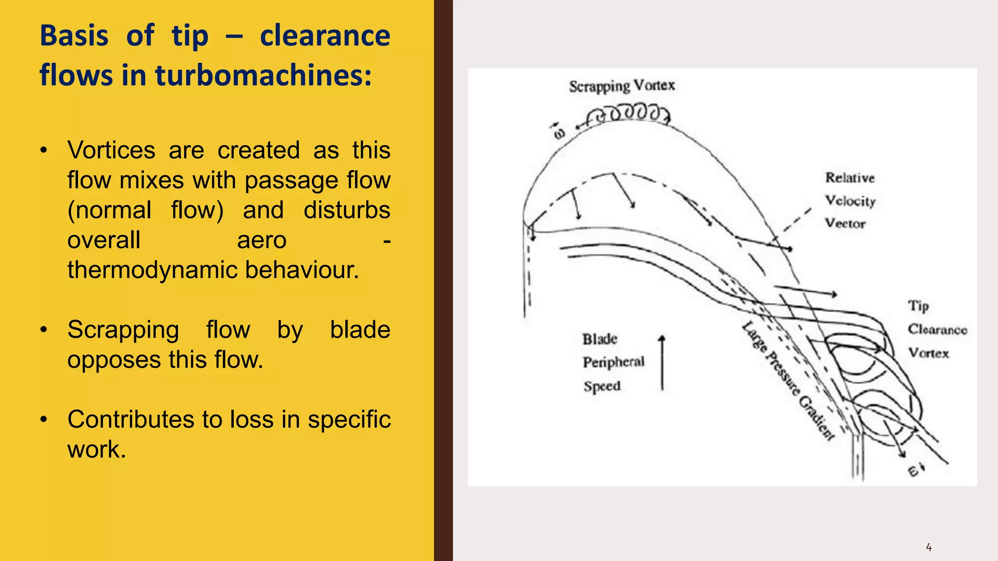


The document discusses tip clearance flows in turbomachines, focusing on their causes, effects, and optimization techniques. Tip clearance is defined as the space between the rotor and casing, which can significantly impact performance by generating vortices and causing losses in efficiency. Recommendations for optimization include minimizing blade angles, maintaining narrow clearance heights, operating in the transonic regime, and employing specific blade contouring techniques.


