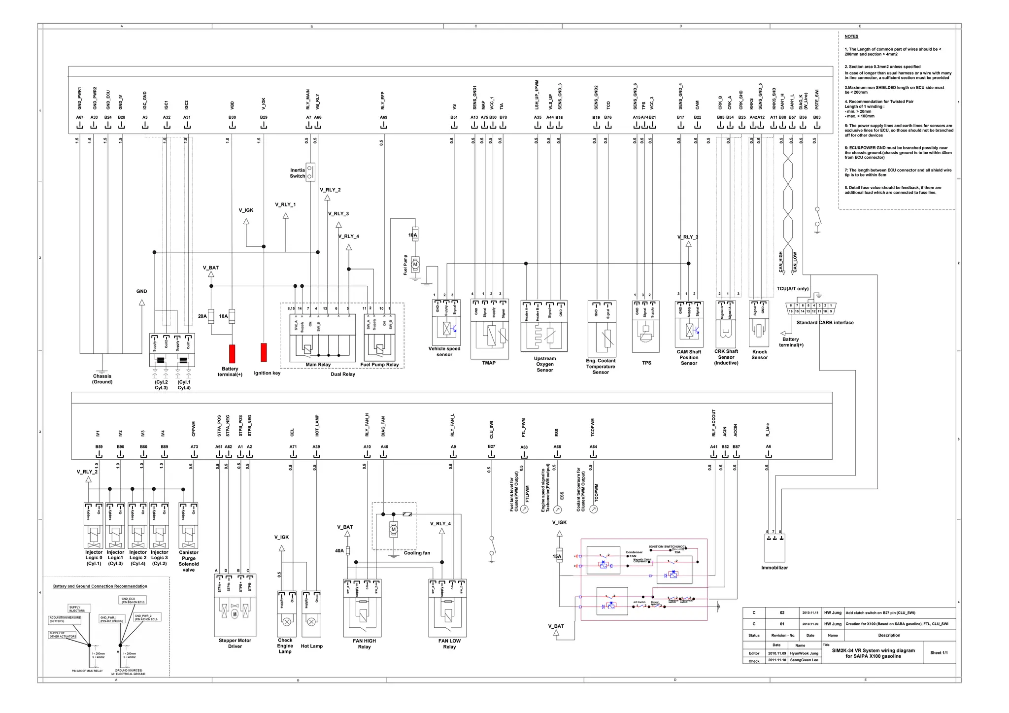
A B D E
A B C D E
1
2
3
4
4
3
2
1
Chassis
(Ground)
GND_PWR1
Battery
terminal(+)
A67
GND_PWR2
A33
GND_ECU
B24
GND_IV
B28
GND
Coil2
Supply
Coil1
Supply
A3
IGC_GND
A32
IGC1
A31
IGC2
20A 10A
V_BAT
B30
VBD
Ignition key
B29
V_IGK
A7
RLY_MAIN
A66
VB_RLY
supply
Signal
GND
TMAP
B50
VCC_1
A75
MAP
A13 B78
SENS_GND1
TIA
Signal
Heater
B
Heater
A
GND
Signal
A35
LSH_UP_1PWM
A44
VLS_UP
SENS_GND_3
B16
Signal
GND
B76
TCO
B19
SENS_GND2
Supply
Signal
GND
A15
SENS_GND_6
A74
TPS
B21
VCC_3
Upstream
Oxygen
Sensor
Eng. Coolant
Temperature
Sensor
TPS
V_RLY_3
GND
Supply
Signal
B17
SENS_GND_4
B22
CAM
Signal
B
Signal
A
B85 B54
CRK_B
CRK_A
B25
CRK_SHD
A11
A42A12
Signal
GND
KNKS
SENS_GND_5
KNKS_SHD
B88 B57
CAN1_H
CAN1_L
CAN_HIGH
CAN_LOW
TCU(A/T only)
CAM Shaft
Position
Sensor
CRK Shaft
Sensor
(Inductive)
Knock
Sensor
Battery
terminal(+)
B56
DIAG_K
(W_Line)
B83
PSTE_SWI
1
2
3
4
5
6
7
8
9
10
11
12
13
14
15
16
Standard CARB interface
supply
On
Injector
Logic 0
(Cyl.1)
supply
On
Injector
Logic1
(Cyl.3)
supply
On
Injector
Logic 2
(Cyl.4)
supply
On
Injector
Logic 3
(Cyl.2)
B59 B90 B60 B89
V_RLY_2
IV1
IV2
IV3
IV4
supply
On
Canistor
Purge
Solenoid
valve
A73
CPPWM
STPA+
STPA-
STPB+
STPB-
A1 A2
A61 A62
STPA_POS
STPA_NEG
STPB_POS
STPB_NEG
sw_a
supply
on
sw_b
FAN HIGH
Relay
sw_a
supply
on
sw_b
FAN LOW
Relay
M
V_RLY_4
A41
RLY_ACCOUT
RLY_FAN_H
RLY_FAN_L
A68
ESS
ESS
1.5
1.5
1.5
1.5
1.5
1.5
1.0
1.5
0.5
0.5
0.5
0.5
0.5
0.5
0.5
0.5
0.5
0.5
0.5
0.5
0.5
0.5
0.5
0.5
0.5
0.5
0.5
0.5
0.5
0.5
0.5
0.5
1.0
1.0
1.0
1.0
0.5
0.5
0.5
0.5
0.5
0.5
0.5
0.5
SIM2K-34 VR System wiring diagram
for SAIPA X100 gasoline
Title
Status Date
Name
Revision - No.
Date
Name Description
C
Sheet 1/1
Editor
Check
01 2010.11.09 HW Jung Creation for X100 (Based on SABA gasoline), FTL, CLU_SWI
V_IGK
8,15 14 7
V_RLY_1
V_RLY_2
V_RLY_3
V_RLY_4
4 13 6 5 11 2
A69
RLY_EFP
M
0.5
10A
Main Relay Fuel Pump Relay
Dual Relay
Fuel
Pump
GND
Supply
Signal
0.5
B51
VS
Engine
speed
signal
to
Tachometer(PWM
output)
V_BAT
V_BAT
V_IGK
B52
ACIN
B87
ACCIN
A64
TCOPWM
TCOPWM
Coolant
temperaure
for
Cluster(PWM
Output)
0.5
0.5
supply
On
supply
On
V_IGK
r
0.5
0.5
A71 A39
CEL
HOT_LAMP
Check
Engine
Lamp
Hot Lamp
0.5
15A
0.5
0.5
Immobilizer
A6
R_Line
0.5
(Cyl.2
Cyl.3)
(Cyl.1
Cyl.4)
A45
DIAG_FAN
10 1
Vehicle speed
sensor
1 2 3 4 2
1 3 1 3 2 2 1 3
1
3 2
5 8
A9
A10
Stepper Motor
Driver
40A Cooling fan
NOTES
1. The Length of common part of wires should be <
200mm and section > 4mm2
2. Section area 0.3mm2 unless specified
In case of longer than usual harness or a wire with many
in-line connector, a sufficient section must be provided
3.Maximum non SHIELDED length on ECU side must
be < 200mm
4. Recommendation for Twisted Pair
Length of 1 winding :
- min. > 20mm
- max. < 100mm
5: The power supply lines and earth lines for sensors are
exclusive lines for ECU, so those should not be branched
off for other devices
6: ECU&POWER GND must be branched possibly near
the chassis ground.(chassis ground is to be within 40cm
from ECU connector)
7: The length between ECU connector and all shield wire
tip is to be within 5cm
8. Detail fuse value should be feedback, if there are
additional load which are connected to fuse line.
A D B C
7
Inertia
Switch
2010.11.09
2011.11.10
HyunWook Jung
SeongGwan Lee
A63
FTL_PWM
FTLPWM
0.5
Fuel
tank
level
for
Cluster(PWM
Output)
B27
CLU_SWI
0.5
C 02 2010.11.11 HW Jung Add clutch switch on B27 pin (CLU_SWI)

Diagrama centauro, turpial.pdf

  • 1.
    A B DE A B C D E 1 2 3 4 4 3 2 1 Chassis (Ground) GND_PWR1 Battery terminal(+) A67 GND_PWR2 A33 GND_ECU B24 GND_IV B28 GND Coil2 Supply Coil1 Supply A3 IGC_GND A32 IGC1 A31 IGC2 20A 10A V_BAT B30 VBD Ignition key B29 V_IGK A7 RLY_MAIN A66 VB_RLY supply Signal GND TMAP B50 VCC_1 A75 MAP A13 B78 SENS_GND1 TIA Signal Heater B Heater A GND Signal A35 LSH_UP_1PWM A44 VLS_UP SENS_GND_3 B16 Signal GND B76 TCO B19 SENS_GND2 Supply Signal GND A15 SENS_GND_6 A74 TPS B21 VCC_3 Upstream Oxygen Sensor Eng. Coolant Temperature Sensor TPS V_RLY_3 GND Supply Signal B17 SENS_GND_4 B22 CAM Signal B Signal A B85 B54 CRK_B CRK_A B25 CRK_SHD A11 A42A12 Signal GND KNKS SENS_GND_5 KNKS_SHD B88 B57 CAN1_H CAN1_L CAN_HIGH CAN_LOW TCU(A/T only) CAM Shaft Position Sensor CRK Shaft Sensor (Inductive) Knock Sensor Battery terminal(+) B56 DIAG_K (W_Line) B83 PSTE_SWI 1 2 3 4 5 6 7 8 9 10 11 12 13 14 15 16 Standard CARB interface supply On Injector Logic 0 (Cyl.1) supply On Injector Logic1 (Cyl.3) supply On Injector Logic 2 (Cyl.4) supply On Injector Logic 3 (Cyl.2) B59 B90 B60 B89 V_RLY_2 IV1 IV2 IV3 IV4 supply On Canistor Purge Solenoid valve A73 CPPWM STPA+ STPA- STPB+ STPB- A1 A2 A61 A62 STPA_POS STPA_NEG STPB_POS STPB_NEG sw_a supply on sw_b FAN HIGH Relay sw_a supply on sw_b FAN LOW Relay M V_RLY_4 A41 RLY_ACCOUT RLY_FAN_H RLY_FAN_L A68 ESS ESS 1.5 1.5 1.5 1.5 1.5 1.5 1.0 1.5 0.5 0.5 0.5 0.5 0.5 0.5 0.5 0.5 0.5 0.5 0.5 0.5 0.5 0.5 0.5 0.5 0.5 0.5 0.5 0.5 0.5 0.5 0.5 0.5 1.0 1.0 1.0 1.0 0.5 0.5 0.5 0.5 0.5 0.5 0.5 0.5 SIM2K-34 VR System wiring diagram for SAIPA X100 gasoline Title Status Date Name Revision - No. Date Name Description C Sheet 1/1 Editor Check 01 2010.11.09 HW Jung Creation for X100 (Based on SABA gasoline), FTL, CLU_SWI V_IGK 8,15 14 7 V_RLY_1 V_RLY_2 V_RLY_3 V_RLY_4 4 13 6 5 11 2 A69 RLY_EFP M 0.5 10A Main Relay Fuel Pump Relay Dual Relay Fuel Pump GND Supply Signal 0.5 B51 VS Engine speed signal to Tachometer(PWM output) V_BAT V_BAT V_IGK B52 ACIN B87 ACCIN A64 TCOPWM TCOPWM Coolant temperaure for Cluster(PWM Output) 0.5 0.5 supply On supply On V_IGK r 0.5 0.5 A71 A39 CEL HOT_LAMP Check Engine Lamp Hot Lamp 0.5 15A 0.5 0.5 Immobilizer A6 R_Line 0.5 (Cyl.2 Cyl.3) (Cyl.1 Cyl.4) A45 DIAG_FAN 10 1 Vehicle speed sensor 1 2 3 4 2 1 3 1 3 2 2 1 3 1 3 2 5 8 A9 A10 Stepper Motor Driver 40A Cooling fan NOTES 1. The Length of common part of wires should be < 200mm and section > 4mm2 2. Section area 0.3mm2 unless specified In case of longer than usual harness or a wire with many in-line connector, a sufficient section must be provided 3.Maximum non SHIELDED length on ECU side must be < 200mm 4. Recommendation for Twisted Pair Length of 1 winding : - min. > 20mm - max. < 100mm 5: The power supply lines and earth lines for sensors are exclusive lines for ECU, so those should not be branched off for other devices 6: ECU&POWER GND must be branched possibly near the chassis ground.(chassis ground is to be within 40cm from ECU connector) 7: The length between ECU connector and all shield wire tip is to be within 5cm 8. Detail fuse value should be feedback, if there are additional load which are connected to fuse line. A D B C 7 Inertia Switch 2010.11.09 2011.11.10 HyunWook Jung SeongGwan Lee A63 FTL_PWM FTLPWM 0.5 Fuel tank level for Cluster(PWM Output) B27 CLU_SWI 0.5 C 02 2010.11.11 HW Jung Add clutch switch on B27 pin (CLU_SWI)