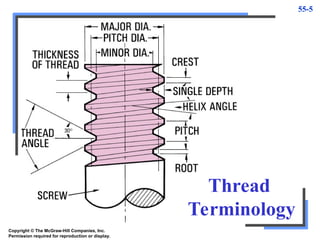
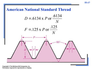
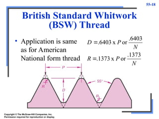
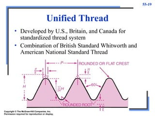
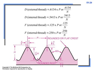
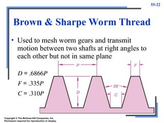
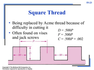
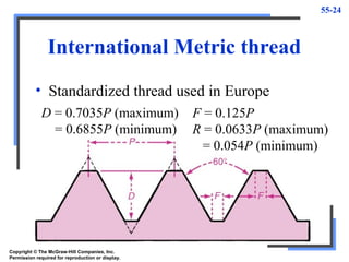
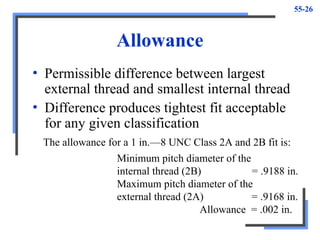
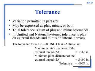
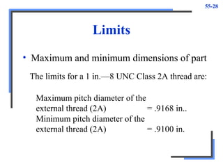
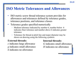
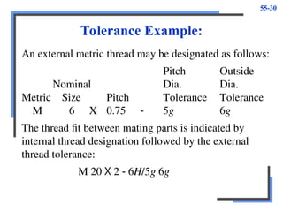
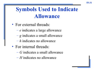
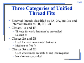
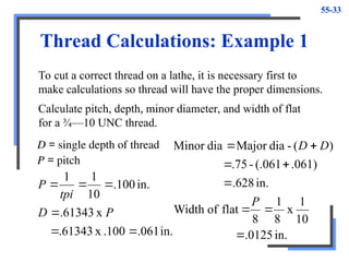
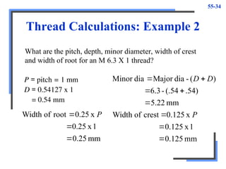
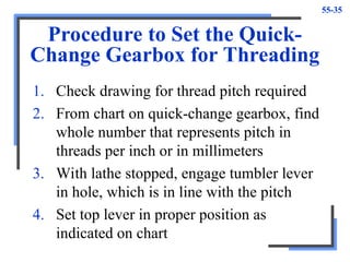
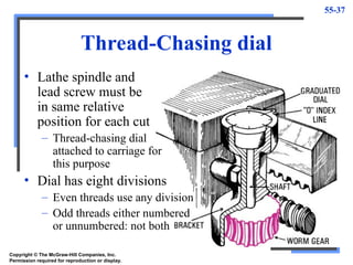
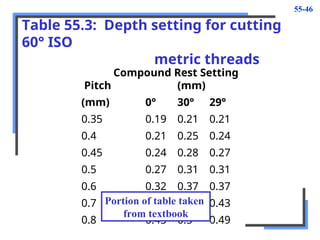
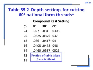
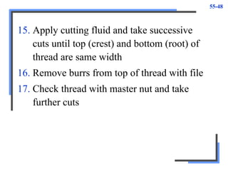
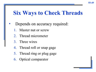
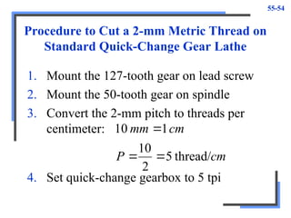
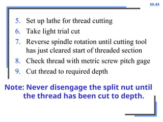
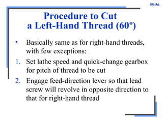
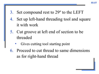
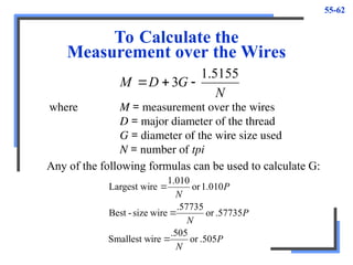
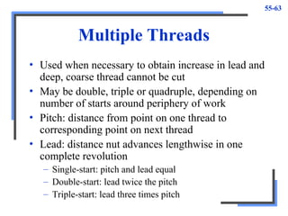
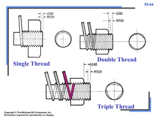
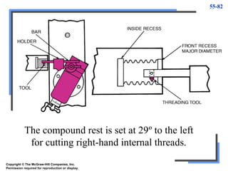
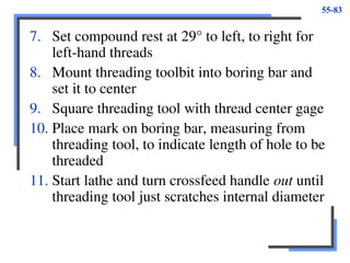
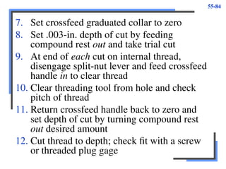
Copyright © The McGraw-Hill Companies, Inc.
Permission required for reproduction or display.
PowerPoint to accompany
Krar • Gill • Smid
Technology of Machine Tools
6th
Edition
Threads and Thread
Cutting
Unit 55
55-2
Objectives
• Recognize and state the purposes of six
common thread forms
• Set up a lathe to cut inch external Unified
threads
• Set up an inch lathe to cut metric threads
• Set up a lathe and cut internal threads
• Set up a lathe and cut external Acme
threads
55-3
Threads
• Used for hundreds of years for holding parts
together, making adjustments, and
transmitting power and motion
• Art of producing threads continually
improved
• Massed-produced by taps, dies, thread
rolling, thread milling, and grinding
55-4
Threads
• Thread
– Helical ridge of uniform section formed on
inside or outside of cylinder or cone
• Used for several purposes:
– Fasten devices such as screws, bolts, studs, and
nuts
– Provide accurate measurement, as in micrometer
– Transmit motion
– Increase force
55-5
Thread
Terminology
Copyright © The McGraw-Hill Companies, Inc.
Permission required for reproduction or display.
55-6
Thread Terminology
• Screw thread
– Helical ridge of uniform section formed on
inside or outside of cylinder or cone
• External thread
– Cut on external surface or cone
• Internal thread
– Produced on inside of cylinder or cone
55-7
• Major diameter
– Largest diameter of external or internal thread
• Minor diameter
– Smallest diameter of external or internal thread
• Pitch diameter
– Diameter of imaginary cylinder that passes
through thread at point where groove and thread
widths are equal
– Equal to major diameter minus single depth of
thread
– Tolerance and allowances given at pitch
diameter line
55-8
• Number of threads per inch
– Number of crests or roots per inch of threaded
section (Does not apply to metric threads)
• Pitch
– Distance from point on one thread to
corresponding point on next thread, measured
parallel to axis
– Expressed in millimeters for metric threads
• Lead
– Distance screw thread advances axially in one
revolution (single-start thread, lead = pitch)
55-9
• Root
– Bottom surface joining sides of two adjacent
threads
– External thread on minor diameter
– Internal thread on major diameter
• Crest
– Top surface joining two sides of thread
– External thread on major diameter
– Internal thread on minor diameter
• Flank
– Thread surface that connects crest with root
55-10
• Depth of thread
– Distance between crest and root measured
perpendicular to axis
• Angle of thread
– Included angle between sides of thread
measured in axial plane
• Helix angle
– Angle that thread makes with plane
perpendicular to thread axis
55-11
• Right-hand thread
– Helical ridge of uniform cross section onto
which nut is threaded in clockwise direction
– When cut on lathe, toolbit
advanced from right to left
• Left-hand thread
– Helical ridge of uniform cross section onto
which nut is threaded in counterclockwise
direction
– When cut on lathe, toolbit
advanced from left to right
Copyright © The McGraw-Hill Companies, Inc.
Permission required for reproduction or display.
55-12
Thread Forms
• April, 1975 ISO came to an agreement
covering standard metric thread profile
– Specifies sizes and pitches for various threads
in new ISO Metric Thread Standard
– Has 25 thread sizes, range in diameter from 1.6
to 100 mm
– Identified by letter M, nominal diameter, and
pitch M 5 X 0.8
55-13
Table 55.1
ISO metric pitch and diameter
combinations
Nominal Thread Nominal Thread
Diameter Pitch Diameter Pitch
(mm) (mm) (mm) (mm)
1.6 0.35 20 2.5
2 0.4 24 3
2.5 0.45 30 3.5
3 0.5 36 4
3.5 0.6 42 4.5
4 0.7 48 5
5 0.8 56 5.5
Portion of table taken
from textbook
55-14
ISO Metric Thread
• 60º included angle, crest = 0.125 times pitch
D (depth of thread) is 0.6143 times pitch
Root is 1/4th
of pitch,
Flat on root (FR) wider than crest (FC)
Copyright © The McGraw-Hill Companies, Inc.
Permission required for reproduction or display.
55-15
ISO Metric Thread
x
.250
x
.125
x
54127
.
0
(external)
P
FR
P
FC
P
D



Copyright © The McGraw-Hill Companies, Inc.
Permission required for reproduction or display.
55-16
American National Standard Thread
• Divided into four main series, all having
same shape and proportions
– National Coarse (NC)
– National Fine (NF)
– National Special (NS)
– National Pipe (NPT)
• Has 60º angle with root and crest truncated
to 1/8th
the pitch
• Used in fabrication, machine construction
55-17
American National Standard Thread
N
P
F
N
P
D
.125
or
x
.125
.6134
or
x
6134
.


Copyright © The McGraw-Hill Companies, Inc.
Permission required for reproduction or display.
55-18
British Standard Whitwork
(BSW) Thread
• Application is same
as for American
National form thread
N
P
R
N
P
D
.1373
or
x
.1373
.6403
or
x
6403
.


Copyright © The McGraw-Hill Companies, Inc.
Permission required for reproduction or display.
55-19
Unified Thread
• Developed by U.S., Britain, and Canada for
standardized thread system
• Combination of British Standard Whitworth and
American National Standard Thread
Copyright © The McGraw-Hill Companies, Inc.
Permission required for reproduction or display.
55-20
N
P
F
N
P
F
N
P
D
N
P
D
.250
or
x
.250
thread)
(internal
.125
or
x
.125
thread)
(external
.5413
or
x
5413
.
thread)
(internal
.6134
or
x
6134
.
thread)
(external




Copyright © The McGraw-Hill Companies, Inc.
Permission required for reproduction or display.
55-21
American National Acme Thread
• Replacing square thread in many cases
• Used for feed screws, jacks, and vises
D = minimum .500P
= maximum .500P + 0.010
F = .3707P
C = .3707P - .0052
(for maximum depth)
Copyright © The McGraw-Hill Companies, Inc.
Permission required for reproduction or display.
55-22
Brown & Sharpe Worm Thread
• Used to mesh worm gears and transmit
motion between two shafts at right angles to
each other but not in same plane
D = .6866P
F = .335P
C = .310P
Copyright © The McGraw-Hill Companies, Inc.
Permission required for reproduction or display.
55-23
Square Thread
• Being replaced by Acme thread because of
difficulty in cutting it
• Often found on vises
and jack screws
D = .500P
F = .500P
C = .500P + .002
Copyright © The McGraw-Hill Companies, Inc.
Permission required for reproduction or display.
55-24
International Metric thread
• Standardized thread used in Europe
F = 0.125P
R = 0.0633P (maximum)
= 0.054P (minimum)
D = 0.7035P (maximum)
= 0.6855P (minimum)
Copyright © The McGraw-Hill Companies, Inc.
Permission required for reproduction or display.
55-25
Thread Fits and Classifications
• Fit
– Relationship between two mating parts
– Determined by amount of clearance or
interference when they are assembled
• Nominal size
– Designation used to identify size of part
• Actual size
– Measured size of thread or part
– Basic size: size from which tolerances are set
55-26
Allowance
• Permissible difference between largest
external thread and smallest internal thread
• Difference produces tightest fit acceptable
for any given classification
The allowance for a 1 in.—8 UNC Class 2A and 2B fit is:
Minimum pitch diameter of the
internal thread (2B) = .9188 in.
Maximum pitch diameter of the
external thread (2A) = .9168 in.
Allowance = .002 in.
55-27
Tolerance
• Variation permitted in part size
• May be expressed as plus, minus, or both
• Total tolerance is sum of plus and minus tolerances
• In Unified and National systems, tolerance is plus
on external threads and minus on internal threads
Maximum pitch diameter of the
external thread (2A) = .9168 in.
Minimum pitch diameter of the
external thread (2A) = .9100 in.
Tolerance = .0068 in.
The tolerance for a 1 in.—8 UNC Class 2A thread is:
55-28
Limits
• Maximum and minimum dimensions of part
Maximum pitch diameter of the
external thread (2A) = .9168 in..
Minimum pitch diameter of the
external thread (2A) = .9100 in.
The limits for a 1 in.—8 UNC Class 2A thread are:
55-29
ISO Metric Tolerances and Allowances
• ISO metric screw thread tolerance system provides for
allowances and tolerances defined by tolerance grades,
tolerance positions, and tolerance classes
• Tolerance grades specified numerically
– Medium tolerance indicated by number 6, number below 6
indicates finer tolerance and number above 6 indicates greater
tolerance
– Tolerance for thread at pitch line and major diameter may be
shown on drawing using the following symbols:
External threads:
e indicates large allowance
g indicates small allowance
h indicates no allowance
Internal threads:
G indicates small allowance
H indicates no allowance
55-30
Tolerance Example:
An external metric thread may be designated as follows:
Pitch Outside
Nominal Dia. Dia.
Metric Size Pitch Tolerance Tolerance
M 6 X 0.75 - 5g 6g
The thread fit between mating parts is indicated by
internal thread designation followed by the external
thread tolerance:
M 20 X 2 - 6H/5g 6g
55-31
Symbols Used to Indicate
Allowance
• For external threads:
– e indicates a large allowance
– g indicates a small allowance
– h indicates no allowance
• For internal threads:
– G indicates a small allowance
– H indicates no allowance
55-32
Three Categories of Unified
Thread Fits
• External threads classified as 1A, 2A, and 3A and
internal threads as 1B, 2B, 3B
• Classes 1A and 1B
– Threads for work that must be assembled
– Loosest fit
• Classes 2A and 2B
– Used for most commercial fasteners
– Medium or free fit
• Classes 3A and 3B
– Used where more accurate fit and lead required
– No allowance provided
55-33
Thread Calculations: Example 1
To cut a correct thread on a lathe, it is necessary first to
make calculations so thread will have the proper dimensions.
D = single depth of thread
P = pitch
in.
.061
.100
x
.61343
x
61343
.
in.
100
.
10
1
1






P
D
tpi
P
Calculate pitch, depth, minor diameter, and width of flat
for a ¾—10 UNC thread.
in.
0125
.
10
1
x
8
1
8
flat
of
Width
in.
628
.
.061)
(.061
-
.75
)
(
-
dia
Major
dia
Minor








P
D
D
55-34
Thread Calculations: Example 2
P = pitch = 1 mm
D = 0.54127 x 1
= 0.54 mm
What are the pitch, depth, minor diameter, width of crest
and width of root for an M 6.3 X 1 thread?
mm
125
.
0
1
x
125
.
0
x
.125
0
crest
of
Width
mm
22
.
5
.54)
(.54
-
6.3
)
(
-
dia
Major
dia
Minor








P
D
D
mm
25
.
0
1
x
0.25
x
25
.
0
root
of
Width


 P
55-35
Procedure to Set the Quick-
Change Gearbox for Threading
1. Check drawing for thread pitch required
2. From chart on quick-change gearbox, find
whole number that represents pitch in
threads per inch or in millimeters
3. With lathe stopped, engage tumbler lever
in hole, which is in line with the pitch
4. Set top lever in proper position as
indicated on chart
55-36
5. Engage sliding gear in or out as required
6. Turn lathe spindle by hand to ensure that
lead screw revolves
7. Recheck lever settings to avoid errors
55-37
Thread-Chasing dial
• Lathe spindle and
lead screw must be
in same relative
position for each cut
– Thread-chasing dial
attached to carriage for
this purpose
• Dial has eight divisions
– Even threads use any division
– Odd threads either numbered
or unnumbered: not both
Copyright © The McGraw-Hill Companies, Inc.
Permission required for reproduction or display.
55-38
Thread Cutting
• Produces a helical ridge of uniform section
on workpiece
• Performed by taking successive cuts with
threading toolbit of same shape as thread
form required
• Work may be held between centers or in
chuck
55-39
Procedure to Set Up a Lathe for
Threading (60º Thread)
1. Set lathe speed to ¼ speed used for turning
2. Set quick-change gearbox for required pitch
in threads per inch or in millimeters
3. Engage lead screw
4. Secure 60º threading toolbit and check
angle using thread center gage
5. Set compound rest at 29º to right; set to left
for left-hand thread
55-40
6. Set cutting tool to height of lathe center
point
7. Mount work between centers
• Make sure lathe dog is tight on work
• If work mounted in chuck, it must be held
tightly
8. Set toolbit at right angles to work, using
thread center gage
9. Arrange apron controls to allow split-nut
lever to be engaged
55-41
Thread-Cutting Operation
Procedure to cut a 60º thread
1. Check major diameter of work for size
2. Start lathe and chamfer end of workpiece
with side of threading tool to just below
minor diameter of thread
3. Mark length to be threaded by cutting
light groove at this point with threading
tool while lathe revolving
55-42
4. Move carriage until point of threading tool
near right-hand end of work
5. Turn crossfeed handle until threading tool
close to diameter, but stop when handle is at
3 o'clock position
6. Hold crossfeed handle in this position and
set graduated collar to zero
7. Turn compound rest handle until threading
tool lightly marks work
55-43
8. Move carriage to right until toolbit clears
end of work
9. Feed compound rest clockwise about .003 in.
10. Engage split-nut lever on correct line of
thread-chasing dial and take trial cut along
length to be threaded
11. At end of cut, turn crossfeed handle
counterclockwise to move toolbit away from
work and disengage split-nut lever
55-44
12. Stop lathe and check number of tpi with
thread pitch gage, rule, or center gage
13. After each cut, turn carriage handwheel to
bring toolbit to start of thread and return
crossfeed handle to zero
14. Set depth of all threading cuts with
compound rest handle
• See Table 55.2 and Table 55.3
55-45
When tool is fed in at 29º, most of the cutting
is done by the leading edge of toolbit.
Copyright © The McGraw-Hill Companies, Inc.
Permission required for reproduction or display.
55-46
Table 55.3: Depth setting for cutting
60° ISO
metric threads
Compound Rest Setting
Pitch (mm)
(mm) 0° 30° 29°
0.35 0.19 0.21 0.21
0.4 0.21 0.25 0.24
0.45 0.24 0.28 0.27
0.5 0.27 0.31 0.31
0.6 0.32 0.37 0.37
0.7 0.37 0.43 0.43
0.8 0.43 0.5 0.49
Portion of table taken
from textbook
55-47
Table 55.2 Depth settings for cutting
60° national form threads*
Compound Rest Setting
tpi 0° 30° 29°
24 .027 .031 .0308
20 .0325 .0375 .037
18 .036 .0417 .041
16 .0405 .0468 .046
14 .0465 .0537 .0525
13 .050 .0577 .057
11 .059 .068 .0674
Portion of table taken
from textbook
55-48
15. Apply cutting fluid and take successive
cuts until top (crest) and bottom (root) of
thread are same width
16. Remove burrs from top of thread with file
17. Check thread with master nut and take
further cuts
55-49
Six Ways to Check Threads
• Depends on accuracy required:
1. Master nut or screw
2. Thread micrometer
3. Three wires
4. Thread roll or snap gage
5. Thread ring or plug gage
6. Optical comparator
55-50
To Reset a Threading Tool
• Must reset when need to remove partly
threaded work from lathe, tool removed for
regrinding, or work slips under lathe dog
Procedure
1. Set up lathe and work for thread cutting
2. Start lathe, toolbit clear of work, engage
split-nut lever on correct line
3. Allow carriage to travel until toolbit
opposite any portion of unfinished thread
55-51
4. Stop lathe, leaving split-nut lever engaged
5. Feed toolbit into thread groove using only
compound rest and crossfeed handles until
right-hand edge of toolbit touches rear side
of thread
6. Set crossfeed graduated collar to zero
7. Back out threading tool using crossfeed
handle, disengage split-nut lever, and
move carriage until toolbit clears start of
thread
55-52
8. Set crossfeed handle back to zero and take
trial cut without setting compound rest
9. Set depth of cut using compound rest
handle and finish thread to required depth
55-53
To Convert an Inch-Designed
Lathe to Metric Threading
• Metric threads may be cut on standard quick-
change gear lathe by using a pair of change gears
having 50 and 127 teeth respectively. Lead screw
has inch dimensions so necessary to convert pitch
in millimeters to centimeters and then into threads
per inch
1 in. = 2.54 cm which gives ration
1:2.54
teeth
127
teeth
50
50
50
x
54
.
2
1

(spindle or drive gear)
(lead screw)
55-54
Procedure to Cut a 2-mm Metric Thread on
Standard Quick-Change Gear Lathe
1. Mount the 127-tooth gear on lead screw
2. Mount the 50-tooth gear on spindle
3. Convert the 2-mm pitch to threads per
centimeter:
cm
P
cm
mm
thread/
5
2
10
1
10



4. Set quick-change gearbox to 5 tpi
55-55
5. Set up lathe for thread cutting
6. Take light trial cut
7. Reverse spindle rotation until cutting tool
has just cleared start of threaded section
8. Check thread with metric screw pitch gage
9. Cut thread to required depth
Note: Never disengage the split nut until
the thread has been cut to depth.
55-56
Procedure to Cut
a Left-Hand Thread (60º)
• Basically same as for right-hand threads,
with few exceptions:
1. Set lathe speed and quick-change gearbox
for pitch of thread to be cut
2. Engage feed-direction lever so that lead
screw will revolve in opposite direction to
that for right-hand thread
55-57
3. Set compound rest to 29º to the LEFT
4. Set up left-hand threading tool and square
it with work
5. Cut groove at left end of section to be
threaded
• Gives cutting tool starting point
6. Proceed to cut thread to same dimensions
as for right-hand thread
55-58
Cutting a Thread on
a Tapered Section
• Use same setup as for regular thread cutting
• Most important that threading tool be set at
90º to axis of work
– Do NOT set it square with tapered surface
55-59
Common Methods of
Measuring Threads
1. Thread ring gage
2. Thread plug gage
3. Thread snap gage
4. Screw thread micrometer
5. Optical comparator
6. Three-wire method
55-60
Three-Wire Method of
Measuring Threads
• Recommended by Bureau of Standards and
National Screw thread Commission
• Three wires of equal diameter placed in thread,
two on one side and one on other side
– Wire used should be hardened and lapped to three times
accuracy of thread to be inspected
• Standard micrometer used to measure distance
over wires (M)
• Different sizes and pitches of threads require
different sizes of wires
55-61
The Three-Wire Method of
Measuring 60º Threads
Copyright © The McGraw-Hill Companies, Inc.
Permission required for reproduction or display.
55-62
To Calculate the
Measurement over the Wires
N
G
D
M
5155
.
1
3 


where M = measurement over the wires
D = major diameter of the thread
G = diameter of the wire size used
N = number of tpi
Any of the following formulas can be used to calculate G:
P
N
P
N
P
N
.505
or
.505
ire
Smallest w
.57735
or
.57735
wire
size
-
Best
1.010
or
010
.
1
re
Largest wi



55-63
Multiple Threads
• Used when necessary to obtain increase in lead and
deep, coarse thread cannot be cut
• May be double, triple or quadruple, depending on
number of starts around periphery of work
• Pitch: distance from point on one thread to
corresponding point on next thread
• Lead: distance nut advances lengthwise in one
complete revolution
– Single-start: pitch and lead equal
– Double-start: lead twice the pitch
– Triple-start: lead three times pitch
55-64
Single Thread
Double Thread
Triple Thread
Copyright © The McGraw-Hill Companies, Inc.
Permission required for reproduction or display.
55-65
Multiple Threads May
be Cut on a Lathe
1. Using accurately slotted driveplate or
faceplate
2. Disengaging intermediate gear of end gear
train and rotating spindle desired amount
3. Using thread-chasing dial
• Only for double-start threads with odd-number
lead
55-66
Procedure to Cut an 8-tpi
Double Thread
1. Set up lathe and cutting tool as for cutting
single-start thread
2. Set quick-change gearbox to 4 tpi
3. Cut first thread to half depth required for 4 tpi
4. Leave crossfeed handle set to depth of
thread and not reading on compound rest
graduated collar
5. Withdraw threading tool from work using
compound rest handle
55-67
6. Revolve work exactly ½ turn
• Remove work from lathe with lathe dog
attached
• Replace work in lathe with tail of dog in slot
exactly opposite one used for first thread
7. Reset crossfeed handle to same position as
when cutting first thread
8. Cut second thread, feeding compound rest
handle until graduated collar at same
setting as for first thread
55-68
Thread-Chasing Dial Method of
Cutting Multiple Threads
• Double-start threads with odd-numbered
lead may be cut using thread-chasing dial
1. Take one cut on thread by engaging split
nut at numbered line on chasing dial
2. Without changing depth of cut, take
another cut at unnumbered line on chasing
dial (second thread will be exactly in
middle of first thread)
3. Continue cutting thread to depth, taking
two passes for every depth-of-cut setting
55-69
Square Threads
• Found in vise screws,
jacks, and other devices
where maximum power
transmission required
• Square threading tool
looks like short cutting-off
tool
• Both sides of square
threading tool must be
ground at angle to
conform to helix angle
of thread
Copyright © The McGraw-Hill Companies, Inc.
Permission required for reproduction or display.
55-70
Square Threading Tool
• Helix angle of thread (angle of square threading
tool) depends on two factors:
– Changes for each different lead on given diameter
(greater lead, greater angle)
– Changes for each different diameter of thread for given
lead (larger diameter, smaller angle)
Copyright © The McGraw-Hill Companies, Inc.
Permission required for reproduction or display.
55-71
To Calculate the Helix Angles of the
Leading and Following Sides of a
Square Thread
diameter
major
of
nce
circumfere
thread
of
lead
angle
following
Tan
diameter
minor
of
nce
circumfere
thread
of
lead
angle
leading
Tan


55-72
Clearance
• Square toolbit must be
provided with approximately
1º clearance on each side
– Makes it thinner at bottom
• For leading side of tool
– Add 1º to calculated helix
angle
• On following side
– Subtract 1º from calculated
angle
Copyright © The McGraw-Hill Companies, Inc.
Permission required for reproduction or display.
55-73
Procedure to Cut Square thread
1. Grind threading tool to proper leading and
following angles
• Width of tool should be ~.002 in. wider than
thread groove
2. Align lathe centers and mount work
3. Set quick-change gearbox for required
number of tpi
4. Set compound rest at 30º to right, which
will provide side movement if necessary to
reset cutting tool
55-74
5. Set threading tool square with work and
center
6. Cut right-hand end of work to minor
diameter for approximately .060 in. long
7. If work permits, cut recess at end of thread
to minor diameter
8. Calculate single depth of thread
N
500
.
9. Start lathe and just touch tool to work
diameter
10. Set crossfeed graduated collar to zero
55-75
11. Set .003 in. depth of cut with crossfeed
screw and take trial cut
12. Check thread with thread pitch gage
13. Apply cutting fluid and cut thread to
depth, moving crossfeed in from .002
to .010 in. for each cut
• Depth of cut will depend on thread size and
nature of workpiece
Note: Since thread sides are square, all
cuts must be set using crossfeed screw
55-76
Acme Thread
• Gradually replacing square thread because
stronger and easier to cut with taps and dies
• Used extensively for lead screws because
29º angle formed by its sides allows split nut
to be engaged during thread cutting
• Provided with .010-in. clearance for both
crest and root on all sizes of threads
55-77
Procedure to Cut an Acme Thread
1. Grind toolbit to fit
end of Acme thread gage
2. Grind point
of tool flat until
it fits into slots
of gage
• Indicates number
of threads per
inch to be cut
Copyright © The McGraw-Hill Companies, Inc.
Permission required for reproduction or display.
55-78
3. Set quick-change gearbox to required
number of threads per inch
4. Set compound rest 14 ½º to right
5. Set Acme threading tool on center and
square it with work using gage
6. At right-hand end of work, cut
section .060 in. long to minor diameter
7. Cut thread to proper depth by feeding
cutting tool, using compound rest
55-79
Measuring Acme Threads
One Wire Method
• Single wire or pin of correct diameter placed in
thread groove and measured with micrometer
• Thread correct size when micrometer reading over
wire is same as major diameter
of thread and wire is tight
in the thread
Diameter of wire to be
used can be calculated
as follows:
Wire diameter = .4872 x pitch
Copyright © The McGraw-Hill Companies, Inc.
Permission required for reproduction or display.
55-80
Internal Threads
• Cutting threads in a hole
– Operation performed on work held in chuck
or collet or mounted on faceplate
– Threading tool similar to boring toolbit
except shape ground to form of thread to be
cut
Procedure
1. Calculate tap drill size of thread
N
1
-
diameter
major
size
drill
Tap 
55-81
2. Mount work to be threaded in chuck or
collet or faceplate
3. Drill hole approximately 1⁄16 in. smaller
than tap drill size in workpiece
4. Mount boring tool in lathe and bore hole to
tap drill size
5. Recess start of hole to major diameter of
thread for .060-in. length
6. If thread does not go through workpiece, a
recess should be cut at end of thread to
major diameter; recess should be wide
enough to allow threading tool to “run out”
and permit time to disengage split-nut lever
55-82
The compound rest is set at 29º to the left
for cutting right-hand internal threads.
Copyright © The McGraw-Hill Companies, Inc.
Permission required for reproduction or display.
55-83
7. Set compound rest at 29° to left, to right for
left-hand threads
8. Mount threading toolbit into boring bar and
set it to center
9. Square threading tool with thread center gage
10. Place mark on boring bar, measuring from
threading tool, to indicate length of hole to be
threaded
11. Start lathe and turn crossfeed handle out until
threading tool just scratches internal diameter
55-84
7. Set crossfeed graduated collar to zero
8. Set .003-in. depth of cut by feeding
compound rest out and take trial cut
9. At end of each cut on internal thread,
disengage split-nut lever and feed crossfeed
handle in to clear thread
10. Clear threading tool from hole and check
pitch of thread
11. Return crossfeed handle back to zero and
set depth of cut by turning compound rest
out desired amount
12. Cut thread to depth; check fit with a screw
or threaded plug gage

THREADS & THREAD CUTTING.ppt for new manufacturers

  • 1.
    Copyright © TheMcGraw-Hill Companies, Inc. Permission required for reproduction or display. PowerPoint to accompany Krar • Gill • Smid Technology of Machine Tools 6th Edition Threads and Thread Cutting Unit 55
  • 2.
    55-2 Objectives • Recognize andstate the purposes of six common thread forms • Set up a lathe to cut inch external Unified threads • Set up an inch lathe to cut metric threads • Set up a lathe and cut internal threads • Set up a lathe and cut external Acme threads
  • 3.
    55-3 Threads • Used forhundreds of years for holding parts together, making adjustments, and transmitting power and motion • Art of producing threads continually improved • Massed-produced by taps, dies, thread rolling, thread milling, and grinding
  • 4.
    55-4 Threads • Thread – Helicalridge of uniform section formed on inside or outside of cylinder or cone • Used for several purposes: – Fasten devices such as screws, bolts, studs, and nuts – Provide accurate measurement, as in micrometer – Transmit motion – Increase force
  • 5.
    55-5 Thread Terminology Copyright © TheMcGraw-Hill Companies, Inc. Permission required for reproduction or display.
  • 6.
    55-6 Thread Terminology • Screwthread – Helical ridge of uniform section formed on inside or outside of cylinder or cone • External thread – Cut on external surface or cone • Internal thread – Produced on inside of cylinder or cone
  • 7.
    55-7 • Major diameter –Largest diameter of external or internal thread • Minor diameter – Smallest diameter of external or internal thread • Pitch diameter – Diameter of imaginary cylinder that passes through thread at point where groove and thread widths are equal – Equal to major diameter minus single depth of thread – Tolerance and allowances given at pitch diameter line
  • 8.
    55-8 • Number ofthreads per inch – Number of crests or roots per inch of threaded section (Does not apply to metric threads) • Pitch – Distance from point on one thread to corresponding point on next thread, measured parallel to axis – Expressed in millimeters for metric threads • Lead – Distance screw thread advances axially in one revolution (single-start thread, lead = pitch)
  • 9.
    55-9 • Root – Bottomsurface joining sides of two adjacent threads – External thread on minor diameter – Internal thread on major diameter • Crest – Top surface joining two sides of thread – External thread on major diameter – Internal thread on minor diameter • Flank – Thread surface that connects crest with root
  • 10.
    55-10 • Depth ofthread – Distance between crest and root measured perpendicular to axis • Angle of thread – Included angle between sides of thread measured in axial plane • Helix angle – Angle that thread makes with plane perpendicular to thread axis
  • 11.
    55-11 • Right-hand thread –Helical ridge of uniform cross section onto which nut is threaded in clockwise direction – When cut on lathe, toolbit advanced from right to left • Left-hand thread – Helical ridge of uniform cross section onto which nut is threaded in counterclockwise direction – When cut on lathe, toolbit advanced from left to right Copyright © The McGraw-Hill Companies, Inc. Permission required for reproduction or display.
  • 12.
    55-12 Thread Forms • April,1975 ISO came to an agreement covering standard metric thread profile – Specifies sizes and pitches for various threads in new ISO Metric Thread Standard – Has 25 thread sizes, range in diameter from 1.6 to 100 mm – Identified by letter M, nominal diameter, and pitch M 5 X 0.8
  • 13.
    55-13 Table 55.1 ISO metricpitch and diameter combinations Nominal Thread Nominal Thread Diameter Pitch Diameter Pitch (mm) (mm) (mm) (mm) 1.6 0.35 20 2.5 2 0.4 24 3 2.5 0.45 30 3.5 3 0.5 36 4 3.5 0.6 42 4.5 4 0.7 48 5 5 0.8 56 5.5 Portion of table taken from textbook
  • 14.
    55-14 ISO Metric Thread •60º included angle, crest = 0.125 times pitch D (depth of thread) is 0.6143 times pitch Root is 1/4th of pitch, Flat on root (FR) wider than crest (FC) Copyright © The McGraw-Hill Companies, Inc. Permission required for reproduction or display.
  • 15.
    55-15 ISO Metric Thread x .250 x .125 x 54127 . 0 (external) P FR P FC P D    Copyright© The McGraw-Hill Companies, Inc. Permission required for reproduction or display.
  • 16.
    55-16 American National StandardThread • Divided into four main series, all having same shape and proportions – National Coarse (NC) – National Fine (NF) – National Special (NS) – National Pipe (NPT) • Has 60º angle with root and crest truncated to 1/8th the pitch • Used in fabrication, machine construction
  • 17.
    55-17 American National StandardThread N P F N P D .125 or x .125 .6134 or x 6134 .   Copyright © The McGraw-Hill Companies, Inc. Permission required for reproduction or display.
  • 18.
    55-18 British Standard Whitwork (BSW)Thread • Application is same as for American National form thread N P R N P D .1373 or x .1373 .6403 or x 6403 .   Copyright © The McGraw-Hill Companies, Inc. Permission required for reproduction or display.
  • 19.
    55-19 Unified Thread • Developedby U.S., Britain, and Canada for standardized thread system • Combination of British Standard Whitworth and American National Standard Thread Copyright © The McGraw-Hill Companies, Inc. Permission required for reproduction or display.
  • 20.
  • 21.
    55-21 American National AcmeThread • Replacing square thread in many cases • Used for feed screws, jacks, and vises D = minimum .500P = maximum .500P + 0.010 F = .3707P C = .3707P - .0052 (for maximum depth) Copyright © The McGraw-Hill Companies, Inc. Permission required for reproduction or display.
  • 22.
    55-22 Brown & SharpeWorm Thread • Used to mesh worm gears and transmit motion between two shafts at right angles to each other but not in same plane D = .6866P F = .335P C = .310P Copyright © The McGraw-Hill Companies, Inc. Permission required for reproduction or display.
  • 23.
    55-23 Square Thread • Beingreplaced by Acme thread because of difficulty in cutting it • Often found on vises and jack screws D = .500P F = .500P C = .500P + .002 Copyright © The McGraw-Hill Companies, Inc. Permission required for reproduction or display.
  • 24.
    55-24 International Metric thread •Standardized thread used in Europe F = 0.125P R = 0.0633P (maximum) = 0.054P (minimum) D = 0.7035P (maximum) = 0.6855P (minimum) Copyright © The McGraw-Hill Companies, Inc. Permission required for reproduction or display.
  • 25.
    55-25 Thread Fits andClassifications • Fit – Relationship between two mating parts – Determined by amount of clearance or interference when they are assembled • Nominal size – Designation used to identify size of part • Actual size – Measured size of thread or part – Basic size: size from which tolerances are set
  • 26.
    55-26 Allowance • Permissible differencebetween largest external thread and smallest internal thread • Difference produces tightest fit acceptable for any given classification The allowance for a 1 in.—8 UNC Class 2A and 2B fit is: Minimum pitch diameter of the internal thread (2B) = .9188 in. Maximum pitch diameter of the external thread (2A) = .9168 in. Allowance = .002 in.
  • 27.
    55-27 Tolerance • Variation permittedin part size • May be expressed as plus, minus, or both • Total tolerance is sum of plus and minus tolerances • In Unified and National systems, tolerance is plus on external threads and minus on internal threads Maximum pitch diameter of the external thread (2A) = .9168 in. Minimum pitch diameter of the external thread (2A) = .9100 in. Tolerance = .0068 in. The tolerance for a 1 in.—8 UNC Class 2A thread is:
  • 28.
    55-28 Limits • Maximum andminimum dimensions of part Maximum pitch diameter of the external thread (2A) = .9168 in.. Minimum pitch diameter of the external thread (2A) = .9100 in. The limits for a 1 in.—8 UNC Class 2A thread are:
  • 29.
    55-29 ISO Metric Tolerancesand Allowances • ISO metric screw thread tolerance system provides for allowances and tolerances defined by tolerance grades, tolerance positions, and tolerance classes • Tolerance grades specified numerically – Medium tolerance indicated by number 6, number below 6 indicates finer tolerance and number above 6 indicates greater tolerance – Tolerance for thread at pitch line and major diameter may be shown on drawing using the following symbols: External threads: e indicates large allowance g indicates small allowance h indicates no allowance Internal threads: G indicates small allowance H indicates no allowance
  • 30.
    55-30 Tolerance Example: An externalmetric thread may be designated as follows: Pitch Outside Nominal Dia. Dia. Metric Size Pitch Tolerance Tolerance M 6 X 0.75 - 5g 6g The thread fit between mating parts is indicated by internal thread designation followed by the external thread tolerance: M 20 X 2 - 6H/5g 6g
  • 31.
    55-31 Symbols Used toIndicate Allowance • For external threads: – e indicates a large allowance – g indicates a small allowance – h indicates no allowance • For internal threads: – G indicates a small allowance – H indicates no allowance
  • 32.
    55-32 Three Categories ofUnified Thread Fits • External threads classified as 1A, 2A, and 3A and internal threads as 1B, 2B, 3B • Classes 1A and 1B – Threads for work that must be assembled – Loosest fit • Classes 2A and 2B – Used for most commercial fasteners – Medium or free fit • Classes 3A and 3B – Used where more accurate fit and lead required – No allowance provided
  • 33.
    55-33 Thread Calculations: Example1 To cut a correct thread on a lathe, it is necessary first to make calculations so thread will have the proper dimensions. D = single depth of thread P = pitch in. .061 .100 x .61343 x 61343 . in. 100 . 10 1 1       P D tpi P Calculate pitch, depth, minor diameter, and width of flat for a ¾—10 UNC thread. in. 0125 . 10 1 x 8 1 8 flat of Width in. 628 . .061) (.061 - .75 ) ( - dia Major dia Minor         P D D
  • 34.
    55-34 Thread Calculations: Example2 P = pitch = 1 mm D = 0.54127 x 1 = 0.54 mm What are the pitch, depth, minor diameter, width of crest and width of root for an M 6.3 X 1 thread? mm 125 . 0 1 x 125 . 0 x .125 0 crest of Width mm 22 . 5 .54) (.54 - 6.3 ) ( - dia Major dia Minor         P D D mm 25 . 0 1 x 0.25 x 25 . 0 root of Width    P
  • 35.
    55-35 Procedure to Setthe Quick- Change Gearbox for Threading 1. Check drawing for thread pitch required 2. From chart on quick-change gearbox, find whole number that represents pitch in threads per inch or in millimeters 3. With lathe stopped, engage tumbler lever in hole, which is in line with the pitch 4. Set top lever in proper position as indicated on chart
  • 36.
    55-36 5. Engage slidinggear in or out as required 6. Turn lathe spindle by hand to ensure that lead screw revolves 7. Recheck lever settings to avoid errors
  • 37.
    55-37 Thread-Chasing dial • Lathespindle and lead screw must be in same relative position for each cut – Thread-chasing dial attached to carriage for this purpose • Dial has eight divisions – Even threads use any division – Odd threads either numbered or unnumbered: not both Copyright © The McGraw-Hill Companies, Inc. Permission required for reproduction or display.
  • 38.
    55-38 Thread Cutting • Producesa helical ridge of uniform section on workpiece • Performed by taking successive cuts with threading toolbit of same shape as thread form required • Work may be held between centers or in chuck
  • 39.
    55-39 Procedure to SetUp a Lathe for Threading (60º Thread) 1. Set lathe speed to ¼ speed used for turning 2. Set quick-change gearbox for required pitch in threads per inch or in millimeters 3. Engage lead screw 4. Secure 60º threading toolbit and check angle using thread center gage 5. Set compound rest at 29º to right; set to left for left-hand thread
  • 40.
    55-40 6. Set cuttingtool to height of lathe center point 7. Mount work between centers • Make sure lathe dog is tight on work • If work mounted in chuck, it must be held tightly 8. Set toolbit at right angles to work, using thread center gage 9. Arrange apron controls to allow split-nut lever to be engaged
  • 41.
    55-41 Thread-Cutting Operation Procedure tocut a 60º thread 1. Check major diameter of work for size 2. Start lathe and chamfer end of workpiece with side of threading tool to just below minor diameter of thread 3. Mark length to be threaded by cutting light groove at this point with threading tool while lathe revolving
  • 42.
    55-42 4. Move carriageuntil point of threading tool near right-hand end of work 5. Turn crossfeed handle until threading tool close to diameter, but stop when handle is at 3 o'clock position 6. Hold crossfeed handle in this position and set graduated collar to zero 7. Turn compound rest handle until threading tool lightly marks work
  • 43.
    55-43 8. Move carriageto right until toolbit clears end of work 9. Feed compound rest clockwise about .003 in. 10. Engage split-nut lever on correct line of thread-chasing dial and take trial cut along length to be threaded 11. At end of cut, turn crossfeed handle counterclockwise to move toolbit away from work and disengage split-nut lever
  • 44.
    55-44 12. Stop latheand check number of tpi with thread pitch gage, rule, or center gage 13. After each cut, turn carriage handwheel to bring toolbit to start of thread and return crossfeed handle to zero 14. Set depth of all threading cuts with compound rest handle • See Table 55.2 and Table 55.3
  • 45.
    55-45 When tool isfed in at 29º, most of the cutting is done by the leading edge of toolbit. Copyright © The McGraw-Hill Companies, Inc. Permission required for reproduction or display.
  • 46.
    55-46 Table 55.3: Depthsetting for cutting 60° ISO metric threads Compound Rest Setting Pitch (mm) (mm) 0° 30° 29° 0.35 0.19 0.21 0.21 0.4 0.21 0.25 0.24 0.45 0.24 0.28 0.27 0.5 0.27 0.31 0.31 0.6 0.32 0.37 0.37 0.7 0.37 0.43 0.43 0.8 0.43 0.5 0.49 Portion of table taken from textbook
  • 47.
    55-47 Table 55.2 Depthsettings for cutting 60° national form threads* Compound Rest Setting tpi 0° 30° 29° 24 .027 .031 .0308 20 .0325 .0375 .037 18 .036 .0417 .041 16 .0405 .0468 .046 14 .0465 .0537 .0525 13 .050 .0577 .057 11 .059 .068 .0674 Portion of table taken from textbook
  • 48.
    55-48 15. Apply cuttingfluid and take successive cuts until top (crest) and bottom (root) of thread are same width 16. Remove burrs from top of thread with file 17. Check thread with master nut and take further cuts
  • 49.
    55-49 Six Ways toCheck Threads • Depends on accuracy required: 1. Master nut or screw 2. Thread micrometer 3. Three wires 4. Thread roll or snap gage 5. Thread ring or plug gage 6. Optical comparator
  • 50.
    55-50 To Reset aThreading Tool • Must reset when need to remove partly threaded work from lathe, tool removed for regrinding, or work slips under lathe dog Procedure 1. Set up lathe and work for thread cutting 2. Start lathe, toolbit clear of work, engage split-nut lever on correct line 3. Allow carriage to travel until toolbit opposite any portion of unfinished thread
  • 51.
    55-51 4. Stop lathe,leaving split-nut lever engaged 5. Feed toolbit into thread groove using only compound rest and crossfeed handles until right-hand edge of toolbit touches rear side of thread 6. Set crossfeed graduated collar to zero 7. Back out threading tool using crossfeed handle, disengage split-nut lever, and move carriage until toolbit clears start of thread
  • 52.
    55-52 8. Set crossfeedhandle back to zero and take trial cut without setting compound rest 9. Set depth of cut using compound rest handle and finish thread to required depth
  • 53.
    55-53 To Convert anInch-Designed Lathe to Metric Threading • Metric threads may be cut on standard quick- change gear lathe by using a pair of change gears having 50 and 127 teeth respectively. Lead screw has inch dimensions so necessary to convert pitch in millimeters to centimeters and then into threads per inch 1 in. = 2.54 cm which gives ration 1:2.54 teeth 127 teeth 50 50 50 x 54 . 2 1  (spindle or drive gear) (lead screw)
  • 54.
    55-54 Procedure to Cuta 2-mm Metric Thread on Standard Quick-Change Gear Lathe 1. Mount the 127-tooth gear on lead screw 2. Mount the 50-tooth gear on spindle 3. Convert the 2-mm pitch to threads per centimeter: cm P cm mm thread/ 5 2 10 1 10    4. Set quick-change gearbox to 5 tpi
  • 55.
    55-55 5. Set uplathe for thread cutting 6. Take light trial cut 7. Reverse spindle rotation until cutting tool has just cleared start of threaded section 8. Check thread with metric screw pitch gage 9. Cut thread to required depth Note: Never disengage the split nut until the thread has been cut to depth.
  • 56.
    55-56 Procedure to Cut aLeft-Hand Thread (60º) • Basically same as for right-hand threads, with few exceptions: 1. Set lathe speed and quick-change gearbox for pitch of thread to be cut 2. Engage feed-direction lever so that lead screw will revolve in opposite direction to that for right-hand thread
  • 57.
    55-57 3. Set compoundrest to 29º to the LEFT 4. Set up left-hand threading tool and square it with work 5. Cut groove at left end of section to be threaded • Gives cutting tool starting point 6. Proceed to cut thread to same dimensions as for right-hand thread
  • 58.
    55-58 Cutting a Threadon a Tapered Section • Use same setup as for regular thread cutting • Most important that threading tool be set at 90º to axis of work – Do NOT set it square with tapered surface
  • 59.
    55-59 Common Methods of MeasuringThreads 1. Thread ring gage 2. Thread plug gage 3. Thread snap gage 4. Screw thread micrometer 5. Optical comparator 6. Three-wire method
  • 60.
    55-60 Three-Wire Method of MeasuringThreads • Recommended by Bureau of Standards and National Screw thread Commission • Three wires of equal diameter placed in thread, two on one side and one on other side – Wire used should be hardened and lapped to three times accuracy of thread to be inspected • Standard micrometer used to measure distance over wires (M) • Different sizes and pitches of threads require different sizes of wires
  • 61.
    55-61 The Three-Wire Methodof Measuring 60º Threads Copyright © The McGraw-Hill Companies, Inc. Permission required for reproduction or display.
  • 62.
    55-62 To Calculate the Measurementover the Wires N G D M 5155 . 1 3    where M = measurement over the wires D = major diameter of the thread G = diameter of the wire size used N = number of tpi Any of the following formulas can be used to calculate G: P N P N P N .505 or .505 ire Smallest w .57735 or .57735 wire size - Best 1.010 or 010 . 1 re Largest wi   
  • 63.
    55-63 Multiple Threads • Usedwhen necessary to obtain increase in lead and deep, coarse thread cannot be cut • May be double, triple or quadruple, depending on number of starts around periphery of work • Pitch: distance from point on one thread to corresponding point on next thread • Lead: distance nut advances lengthwise in one complete revolution – Single-start: pitch and lead equal – Double-start: lead twice the pitch – Triple-start: lead three times pitch
  • 64.
    55-64 Single Thread Double Thread TripleThread Copyright © The McGraw-Hill Companies, Inc. Permission required for reproduction or display.
  • 65.
    55-65 Multiple Threads May beCut on a Lathe 1. Using accurately slotted driveplate or faceplate 2. Disengaging intermediate gear of end gear train and rotating spindle desired amount 3. Using thread-chasing dial • Only for double-start threads with odd-number lead
  • 66.
    55-66 Procedure to Cutan 8-tpi Double Thread 1. Set up lathe and cutting tool as for cutting single-start thread 2. Set quick-change gearbox to 4 tpi 3. Cut first thread to half depth required for 4 tpi 4. Leave crossfeed handle set to depth of thread and not reading on compound rest graduated collar 5. Withdraw threading tool from work using compound rest handle
  • 67.
    55-67 6. Revolve workexactly ½ turn • Remove work from lathe with lathe dog attached • Replace work in lathe with tail of dog in slot exactly opposite one used for first thread 7. Reset crossfeed handle to same position as when cutting first thread 8. Cut second thread, feeding compound rest handle until graduated collar at same setting as for first thread
  • 68.
    55-68 Thread-Chasing Dial Methodof Cutting Multiple Threads • Double-start threads with odd-numbered lead may be cut using thread-chasing dial 1. Take one cut on thread by engaging split nut at numbered line on chasing dial 2. Without changing depth of cut, take another cut at unnumbered line on chasing dial (second thread will be exactly in middle of first thread) 3. Continue cutting thread to depth, taking two passes for every depth-of-cut setting
  • 69.
    55-69 Square Threads • Foundin vise screws, jacks, and other devices where maximum power transmission required • Square threading tool looks like short cutting-off tool • Both sides of square threading tool must be ground at angle to conform to helix angle of thread Copyright © The McGraw-Hill Companies, Inc. Permission required for reproduction or display.
  • 70.
    55-70 Square Threading Tool •Helix angle of thread (angle of square threading tool) depends on two factors: – Changes for each different lead on given diameter (greater lead, greater angle) – Changes for each different diameter of thread for given lead (larger diameter, smaller angle) Copyright © The McGraw-Hill Companies, Inc. Permission required for reproduction or display.
  • 71.
    55-71 To Calculate theHelix Angles of the Leading and Following Sides of a Square Thread diameter major of nce circumfere thread of lead angle following Tan diameter minor of nce circumfere thread of lead angle leading Tan  
  • 72.
    55-72 Clearance • Square toolbitmust be provided with approximately 1º clearance on each side – Makes it thinner at bottom • For leading side of tool – Add 1º to calculated helix angle • On following side – Subtract 1º from calculated angle Copyright © The McGraw-Hill Companies, Inc. Permission required for reproduction or display.
  • 73.
    55-73 Procedure to CutSquare thread 1. Grind threading tool to proper leading and following angles • Width of tool should be ~.002 in. wider than thread groove 2. Align lathe centers and mount work 3. Set quick-change gearbox for required number of tpi 4. Set compound rest at 30º to right, which will provide side movement if necessary to reset cutting tool
  • 74.
    55-74 5. Set threadingtool square with work and center 6. Cut right-hand end of work to minor diameter for approximately .060 in. long 7. If work permits, cut recess at end of thread to minor diameter 8. Calculate single depth of thread N 500 . 9. Start lathe and just touch tool to work diameter 10. Set crossfeed graduated collar to zero
  • 75.
    55-75 11. Set .003in. depth of cut with crossfeed screw and take trial cut 12. Check thread with thread pitch gage 13. Apply cutting fluid and cut thread to depth, moving crossfeed in from .002 to .010 in. for each cut • Depth of cut will depend on thread size and nature of workpiece Note: Since thread sides are square, all cuts must be set using crossfeed screw
  • 76.
    55-76 Acme Thread • Graduallyreplacing square thread because stronger and easier to cut with taps and dies • Used extensively for lead screws because 29º angle formed by its sides allows split nut to be engaged during thread cutting • Provided with .010-in. clearance for both crest and root on all sizes of threads
  • 77.
    55-77 Procedure to Cutan Acme Thread 1. Grind toolbit to fit end of Acme thread gage 2. Grind point of tool flat until it fits into slots of gage • Indicates number of threads per inch to be cut Copyright © The McGraw-Hill Companies, Inc. Permission required for reproduction or display.
  • 78.
    55-78 3. Set quick-changegearbox to required number of threads per inch 4. Set compound rest 14 ½º to right 5. Set Acme threading tool on center and square it with work using gage 6. At right-hand end of work, cut section .060 in. long to minor diameter 7. Cut thread to proper depth by feeding cutting tool, using compound rest
  • 79.
    55-79 Measuring Acme Threads OneWire Method • Single wire or pin of correct diameter placed in thread groove and measured with micrometer • Thread correct size when micrometer reading over wire is same as major diameter of thread and wire is tight in the thread Diameter of wire to be used can be calculated as follows: Wire diameter = .4872 x pitch Copyright © The McGraw-Hill Companies, Inc. Permission required for reproduction or display.
  • 80.
    55-80 Internal Threads • Cuttingthreads in a hole – Operation performed on work held in chuck or collet or mounted on faceplate – Threading tool similar to boring toolbit except shape ground to form of thread to be cut Procedure 1. Calculate tap drill size of thread N 1 - diameter major size drill Tap 
  • 81.
    55-81 2. Mount workto be threaded in chuck or collet or faceplate 3. Drill hole approximately 1⁄16 in. smaller than tap drill size in workpiece 4. Mount boring tool in lathe and bore hole to tap drill size 5. Recess start of hole to major diameter of thread for .060-in. length 6. If thread does not go through workpiece, a recess should be cut at end of thread to major diameter; recess should be wide enough to allow threading tool to “run out” and permit time to disengage split-nut lever
  • 82.
    55-82 The compound restis set at 29º to the left for cutting right-hand internal threads. Copyright © The McGraw-Hill Companies, Inc. Permission required for reproduction or display.
  • 83.
    55-83 7. Set compoundrest at 29° to left, to right for left-hand threads 8. Mount threading toolbit into boring bar and set it to center 9. Square threading tool with thread center gage 10. Place mark on boring bar, measuring from threading tool, to indicate length of hole to be threaded 11. Start lathe and turn crossfeed handle out until threading tool just scratches internal diameter
  • 84.
    55-84 7. Set crossfeedgraduated collar to zero 8. Set .003-in. depth of cut by feeding compound rest out and take trial cut 9. At end of each cut on internal thread, disengage split-nut lever and feed crossfeed handle in to clear thread 10. Clear threading tool from hole and check pitch of thread 11. Return crossfeed handle back to zero and set depth of cut by turning compound rest out desired amount 12. Cut thread to depth; check fit with a screw or threaded plug gage