
Recommended
Recommended
More Related Content
What's hot
What's hot (20)
Similar to Toshniwal - Thermal mass flow meters and controller
Similar to Toshniwal - Thermal mass flow meters and controller (20)
More from SangeethaS99
Recently uploaded
Recently uploaded (20)
Toshniwal - Thermal mass flow meters and controller
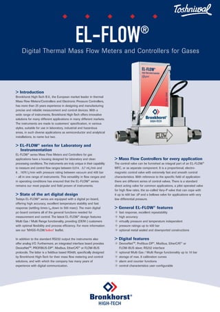
- 1. > Introduction Bronkhorst High-Tech B.V., the European market leader in thermal Mass Flow Meters/Controllers and Electronic Pressure Controllers, has more than 25 years experience in designing and manufacturing precise and reliable measurement and control devices. With a wide range of instruments, Bronkhorst High-Tech offers innovative solutions for many different applications in many different markets. The instruments are made to customers’ specification, in various styles, suitable for use in laboratory, industrial and hazardous areas, in such diverse applications as semiconductor and analytical installations, to name but two. > EL-FLOW® series for Laboratory and Instrumentation EL-FLOW® series Mass Flow Meters and Controllers for gas applications have a housing designed for laboratory and clean processing conditions. The instruments are truly unique in their capability to measure and control flow ranges between 0,014…0,7 mln/min and 8…1670 ln/min with pressure rating between vacuum and 400 bar – all in one range of instruments. This versatility in flow ranges and in operating conditions has ensured that the EL-FLOW® series remains our most popular and field proven of instruments. State of the art digital design Todays EL-FLOW® series are equipped with a digital pc-board, offering high accuracy, excellent temperature stability and fast response (settling times t98 down to 500 msec). The main digital pc-board contains all of the general functions needed for measurement and control. The latest EL-FLOW® design features Multi Gas / Multi Range functionality, providing (OEM-) customers with optimal flexibility and process efficiency. For more information see our ‘MASS-FLOWSelect’ leaflet. In addition to the standard RS232 output the instruments also offer analog I/O. Furthermore, an integrated interface board provides DeviceNetTM , PROFIBUS-DP® , Modbus, EtherCAT® or FLOW-BUS protocols. The latter is a fieldbus based RS485, specifically designed by Bronkhorst High-Tech for their mass flow metering and control solutions, and with which the company has many years of experience with digital communication. Mass Flow Controllers for every application The control valve can be furnished as integral part of an EL-FLOW® MFC, or as separate component. It is a proportional, electro- magnetic control valve with extremely fast and smooth control characteristics. With reference to the specific field of application there are different series of control valves. There is a standard direct acting valve for common applications, a pilot operated valve for high flow rates, the so-called Vary-P valve that can cope with 6 up to 400 bar ΔP and a bellows valve for applications with very low differential pressure. General EL-FLOW® features u fast response, excellent repeatability u high accuracy u virtually pressure and temperature independent u pressure ratings up to 400 bar u optional metal sealed and downported constructions Digital features u DeviceNetTM , Profibus-DP® , Modbus, EtherCAT® or FLOW-BUS slave; RS232 interface u optional Multi Gas / Multi Range functionality up to 10 bar u storage of max. 8 calibration curves u alarm and counter functions u control characteristics user-configurable EL-FLOW® Digital Thermal Mass Flow Meters and Controllers for Gases
- 2. Technical specifications Measurement / control system Accuracy (incl. linearity) : standard: ±0,5% Rd plus ±0,1%FS (based on actual calibration) (±1% FS for ranges 3...5 mln/min; ±2% FS for ranges 3 mln/min) Turndown : 1 : 50 (in digital mode up to 1:187,5) Repeatability : 0,2% Rd Settling time (controller) : standard: 1…2 seconds option: down to 500 msec Control stability : ±0,1% FS (typical for 1 ln/min N2) Operating temperature : -10…+70°C Temperature sensitivity : zero: 0,05% FS/°C; span: 0,05% Rd/°C Pressure sensitivity : 0,1% Rd/bar typical N2; 0,01% Rd/bar typical H2 Leak integrity, outboard : tested 2 x 10⁻⁹ mbar l/s He Attitude sensitivity : max. error at 90° off horizontal 0,2% at 1 bar, typical N2 Warm-up time : 30 min. for optimum accuracy 2 min. for accuracy ± 2% FS Mechanical parts Material (wetted parts) : stainless steel 316L or comparable Process connections : compression type or face seal couplings Seals : standard: Viton; options: EPDM, Kalrez (FFKM) Ingress protection (housing) : IP40 Electrical properties Power supply : +15…24 Vdc Power consumption : meter: 70 mA; controller: max. 320 mA; add 50 mA for Profibus, if applicable Analog output/command : 0...5 (10) Vdc or 0 (4)…20 mA (sourcing output) Digital communication : standard: RS232 options: Profibus-DP® , DeviceNetTM , EtherCAT® , Modbus, FLOW-BUS Electrical connection Analog/RS232 : 9-pin D-connector (male); Profibus-DP® : bus: 9-pin D-connector (female); power: 9-pin D-connector (male); DeviceNetTM : 5-pin M12-connector (male); EtherCAT® : 2 x RJ45 modular jack (in/out) Modbus-RTU/FLOW-BUS : RJ45 modular jack Technical specifications and dimensions subject to change without notice. Models and flow ranges (based on Air) Mass Flow Meters (MFM); PN100 (pressure rating 100 bar) Model min. flow max. flow F-110C 0,014…0,7 mln/min 0,06…9 mln/min F-111B 0,16…8 mln/min 0,16…25 ln/min F-111AC 0,4…20 ln/min 0,6…100 ln/min F-112AC 0,8…40 ln/min 1,4…250 ln/min F-113AC 4…200 ln/min 8…1670 ln/min For ranges of 200 or 400 bar rated MFMs see model number identification. Mass Flow Controllers (MFC); PN64 / PN100 Model min. flow max. flow F-200CV/F-210CV 1) 0,014…0,7 mln/min 0,06…9 mln/min F-201CV/F-211CV 1) 0,16…8 mln/min 0,16…25 ln/min F-201AV/F-211AV 1) 0,4…20 ln/min 0,6…100 ln/min F-202AV/F-212AV 2) 0,8…40 ln/min 1,4…250 ln/min F-203AV/F-213AV 3) 4…200 ln/min 8…1670 ln/min 1) Kv-max = 6,6 x 10⁻² 2) Kv-max = 0,4 3) Kv-max = 1,5 MFCs for high-pressure / high-ΔP applications; PN400 Model min. flow max. flow F-230M 0,2…10 mln/min 10…500 mln/min F-231M 10…500 mln/min 0,2…10 ln/min F-232M 0,2…10 ln/min 2…100 ln/min Thermal mass flow measuring principle The heart of the thermal mass flow meter/controller is the sensor, that consists of a stainless steel capillary tube with resistance thermometer elements. A part of the gas flows through this bypass sensor, and is warmed up by heating elements. Consequently the measured temperatures T1 and T2 drift apart. The temperature difference is directly proportional to mass flow through the sensor. In the main channel Bronkhorst High-Tech applies a patented laminar flow element consisting of a stack of stainless steel discs with precision-etched flow channels. Thanks to the perfect flow-split the sensor output is proportional to the total mass flow rate. Temperature profile without flow Temperature profile with flow Ambient temperature Turbulence filter Flow Measured T Mediumtemperature Heater1and Temperature measurement1 Heater2and Temperature measurement2 Sensor tube Laminar flow element ΔT = k.Cp.Øm ΔT = T2-T1 in Kelvin Cp = specific heat Øm = mass flow F-111B Mass Flow Meter
- 3. Dimensions Mass Flow Meter Dimensions in mm. Mass Flow Controller Dimensions in mm. Fields of application The EL-FLOW® series have been successfully applied in a wide variety of both OEM and laboratory applications in the following markets (typically): u Semiconductor processing u Analysis and environmental measurements u Burner control u Vacuum technology u Surface treatment installations u Process control in food, pharmaceutical and (petro-) chemical industries To give an impression of the many varied applications, we hereby sketch some basic examples. In reality, these applications are commonly far more complex and with far more variations and adaptations. Burner control Burner control using Mass Flow Controllers brings many advan- tages compared to conventional systems, where flow is adjusted through needle valves. When burner orifices get clogged or when gas supply pressure varies, an MFC will automatically adapt to the changed conditions. For the control of relatively large flows with low differential pressure, which is typical for natural gas or CH4, Bronkhorst High-Tech offers mass flow meters with separate pressure compensated bellows valves. Making gas mixtures MFC’s are often used to make precise and stable mixtures of two or more gases. A Bronkhorst PS/Readout system can be applied to maintain the ratio of mixed gases by operating in master-slave mode. In the example above, the flow range of gas 1 is much smaller than the other. For this purpose Bronkhorst High-Tech developed a gas mixer, to guarantee a homogeneous gas mixture. Feeding of reactors Flow control is often combined with the control of reactor pres- sure, using an EL-PRESS back pressure controller, or as depicted, an EL-PRESS Pressure Meter with integrated PI-controller. Typical applications: high pressure hydrogenation systems and autoclave processes using a 400 bar rated Mass Flow Controller with Vary-P control valve. C H A K B C H A K B Model A B C H K Weight (kg) F-110C (1/8” OD) 47 98 47 111 25 0,4 F-111B (1/4” OD) 69 126 47 111 25 0,5 F-111AC (1/4” OD) 69 126 47 123 26 0,6 F-112AC (1/2” OD) 65 130 47 139 59 1,3 F-113AC (1/2” OD) 112 179 47 153 74 3,0 Model A B C H K Weight (kg) F-200CV/F-210CV (1/8” OD) 77 128 47 111 25 0,6 F-201CV/F-211CV (1/4” OD) 77 134 47 111 25 0,6 F-201AV/F-211CV (1/4” OD) 78 135 47 123 26 0,7 F-202AV/F-212AV (1/2” OD) 112 169 47 139 59 2,1 F-203AV/F-213AV (1/2” OD) 171 238 47 153 74 4,9 F-230M/F-231M/F-232M (1/4” OD) 115 172 47 163 69 3,4 Gas 2 Gas mixer Gas mixture Gas 1 Pressure Meter with integrated PI-controller Autoclave with Pmax 400 bar Product Reaction gas
- 4. Base 0 Valve only 1 Meter 2 Controller Pressure rating 0 64 bar 1 100 bar 2 200 bar 3 400 bar Ranges for PN64/PN100 Flow Meters/Controllers 0C/0CV 0…0,7 / 0…9 mln/min 1B/1CV 0…8 / 0…25000 mln/min 1AC/1AV 0…20 / 0…100 ln/min 2AC/2AV 0…40 / 0…250 ln /min 3AC/3AV 0…200 / 0…1670 ln/min for PN200/PN400 Flow Meters 0M 0…10 / 0…15 mln/min 1M 0…15 / 0…20000 mln/min 2M 0…10 / 0…250 ln/min 3M 0…200 / 0…1250 ln/min for PN400 Flow Controllers 0M 0…10 / 0…500 mln/min 1M 0…0,5 / 0…10 ln/min 2M 0…10 / 0…100 ln/min Nominal range Factory selected Communication (I/O) A RS232 + analog (n/c control) B RS232 + analog (n/o control) D RS232 + DeviceNetTM (n/c control) E RS232 + DeviceNetTM (n/o control) M RS232 + Modbus (n/c control) N RS232 + Modbus (n/o control) P RS232 + Profibus-DP® (n/c control) Q RS232 + Profibus-DP® (n/o control) R RS232 + FLOW-BUS (n/c control) S RS232 + FLOW-BUS (n/o control) T RS232 + EtherCAT® (n/c control) U RS232 + EtherCAT® (n/o control) Analog output A 0…5 Vdc B 0…10 Vdc F 0…20 mA sourcing G 4…20 mA sourcing Supply voltage D +15…24 Vdc Connections (in/out) 1 1 /8“ OD compression type 2 1 /4“ OD compression type 3 6 mm OD compression type 4 12 mm OD compression type 5 1 /2” OD compression type 6 20 mm OD compression type 8 1 /4” Face seal male 9 other Internal seals V Viton (factory standard) E EPDM K Kalrez (FFKM) Model number identification F - N N NAA - NNN - A A A - NN - A F-112AC Mass Flow Meter F-231M Mass Flow Controller for high pressure applicationsF-203AV Mass Flow Controller for high flow applications Nijverheidsstraat 1a, NL-7261 AK Ruurlo Netherlands T +31(0)573 45 88 00 F +31(0)573 45 88 08 I www.bronkhorst.com E info@bronkhorst.com E.ELL.1012.G ©BHT2010-088