SlideShare a Scribd company logo
1 of 33
RMK SENIOR SECONDARY SCHOOL
THIRUVERKADU, CHENNAI-77
ACADEMIC YEAR: 2019-20
Project submitted to the Central Board of
Secondary Education (CBSE) in partial
fulfilment for the requirement of All India
Senior School Certificate Examination
(AISSCE) 2019-’20,
Department of physics.
TOPIC: PREPARATION OF A MICROSCOPE
BY
NAME: D.YASHWANTH
REG.NO: ……………………………………
1 | P H O T O E L E C T R I C E F F E C T
GUIDED BY
Mr. J.Mariappan
RMK SENIOR SECONDARY SCHOOL
THIRUVERKADU, CHENNAI-77
BONAFIDE CERTIFICATE
Certified to be the bonafide record of the project work done by
REG.NO:- of class
XII in senior physics laboratory during the academic year 2019-20.
TEACHER IN-CHARGE
Submitted for all India Senior Secondary Practical Physics
Examination held on .
INTERNAL EXAMINER EXTERNAL EXAMINER
2 | P H O T O E L E C T R I C E F F E C T
ACKNOWLEDGEMENT
It is customary for me to acknowledgethe contributions
and suggestions received from various sources.
First of all I would like to thank god almighty for giving me
wisdom and knowledge to showcase my talent.
I am very thankful to our PrincipalMrs. Sudha Malini for
giving me the golden opportunityto do this wonderful
project.
I wish to acknowledgethe tremendousamount of help
received from my Physics Teacher Mr J.Mariaapan,without
whose help and encouragement it would not have been
possible for me to complete this project.
I wish to express my gratitude to all non-teaching staff who
helped me to complete my project.
Whatever words I choose cannot sufficiently express my
deep sense of gratitude towards my parents for their
constant understanding, assistance, inspirationandmoral
support in completing this project.
3 | P H O T O E L E C T R I C E F F E C T
I would also like to acknowledge my thanks to my friends
for their valuablesuggestions and timely help.
PHOTOELEC
TRIC
4 | P H O T O E L E C T R I C E F F E C T
EFFECT
BRAINED BY:
S.HITESH BORHA
CONTENT
INTRODUCTION
HISTORY
Hertz’s Observations
Hallwach’s and
Lenard’s Observations
5 | P H O T O E L E C T R I C E F F E C T
Experimental study of
photoelectric effect
Laws of photoelectric
emission
Failure of classical
wave theory to explain
photoelectric effect
Einstein’s Theory
Uses and Effects
Bibliography
INTRODUCTION
The photoelectric effect is the emission of electrons
or other free carriers when light shines on a
material. Electrons emitted in this manner can be called
photo electrons. This phenomenon is commonly studied
in electronic physics, as well as in fields of chemistry,
such as quantum chemistry or electrochemistry.
According to classical electromagnetic theory, this effect
can be attributed to the transfer of energy from the light
6 | P H O T O E L E C T R I C E F F E C T
to an electron. From this perspective, an alteration in the
intensity of light would induce changes in the kinetic
energy of the electrons emitted from the metal.
Furthermore, according to this theory, a sufficiently dim
light would be expected to show a time lag between the
initial shining of its light and the subsequent emission of
an electron. However, the experimental results did not
correlate with either of the two predictions made by
classical theory.
Instead, electrons are dislodged only by the
impingement of photons when those photons reach or
exceed a threshold frequency (energy). Below that
threshold, no electrons are emitted from the material
regardless of the light intensity or the length of time of
exposure to the light. (Rarely, an electron will escape by
absorbing two or more quanta. However, this is
extremely rare because by the time it absorbs enough
quanta to escape, the electron will probably have
emitted the rest of the quanta.) To make sense of the
fact that light can eject electrons even if its intensity is
low, Albert Einstein proposed that a beam of light is not
a wave propagating through space, but rather a
collection of discrete wave packets (photons), each with
energy hν. This shed light on Max Planck's previous
discovery of the Planck relation (E = hν) linking energy
(E) and frequency (ν) as arising from quantization of
energy. The factor h is known as the Planck constant.
In 1887, Heinrich Hertz discovered that electrodes
illuminated with ultraviolet light create electric sparks
more easily. In 1900, while studying black-body
radiation, the German physicist Max Planck suggested
7 | P H O T O E L E C T R I C E F F E C T
that the energy carried by electromagnetic waves could
only be released in "packets" of energy. In 1905, Albert
Einstein published a paper advancing the hypothesis
that light energy is carried in discrete quantized packets
to explain experimental data from the photoelectric
effect. This model contributed to the development of
quantum mechanics. In 1914, Millikan's Experiment
supported Einstein's model of the photoelectric effect.
Einstein was awarded the Nobel Prize in 1921 for "his
discovery of the law of the photoelectric effect", and
Robert Millikan was awarded the Nobel Prize in 1923 for
"his work on the elementary charge of electricity and on
the photoelectric effect".
The photoelectric effect requires photons with energies
approaching zero (in the case of negative electron
affinity) to over 1 MeV for core electrons in elements with
a high atomic number. Emission of conduction electrons
from typical metals usually requires a few electron-volts,
corresponding to short-wavelength visible or ultraviolet light.
Study of the photoelectric effect led to important steps in
understanding the quantum nature of light and electrons and
influenced the formation of the concept of wave–particle duality.
Other phenomena where light affects the movement of electric
charges include the photoconductive effect (also known as
photoconductivity or photo resistivity), the photovoltaic effect,
and the photo electrochemical effect.
8 | P H O T O E L E C T R I C E F F E C T
Photoemission can occur from any material, but it is most easily
observable from metals or other conductors because the process
produces a charge imbalance, and if this charge imbalance is not
neutralized by current flow (enabled by conductivity), the potential
barrier to emissionincreases until the emission current ceases. It is
also usual to have the emitting surface in a vacuum, since gases
impede the flow of photoelectrons and make them difficult to
observe.Additionally, the energy barrier to photoemission is usually
increased by thin oxide layers on metal surfaces if the metal has
been exposed to oxygen, so most practical experiments and
devices based on the photoelectric effect use clean metal surfaces
in a vacuum.
When the photoelectron is emitted into a solid rather than into a
vacuum, the term internal photoemission is often used, and
emissioninto a vacuum distinguished as external photoemission.
9 | P H O T O E L E C T R I C E F F E C T
10 | P H O T O E L E C T R I C E F F E C T
HISTORY
When a surface is exposed to electromagnetic radiation above a
certain threshold frequency (typically visible light for alkali metals, near
ultraviolet for other metals, and extreme ultraviolet for non-metals), the
radiation is absorbed and electrons are emitted. Light, and especially
ultra-violet light, discharges negatively electrified bodies with the
production of rays of the same nature as cathode rays. Under certain
circumstances it can directly ionize gases. The first of these
phenomena was discovered by Hertz and Hallwachs in 1887. The
second was announced first by Philipp Lenard in 1900.
The ultra-violet light to produce these effects may be obtained
from an arc lamp, or by burning magnesium, or by sparking with an
induction coil between zinc or cadmium terminals, the light from which
is very rich in ultra-violet rays. Sunlight is not rich in ultra-violet rays, as
these have been absorbed by the atmosphere, and it does not
produce nearly so large an effect as the arc-light. Many substances
besides metals discharge negative electricity under the action of
ultraviolet light: lists of these substances will be found in papers by G.
C. Schmidt and O. Knoblauch.
11 | P H O T O E L E C T R I C E F F E C T
19TH CENTURY:
In 1839, Alexandre Edmond Becquerel discovered the photovoltaic
effect while studying the effect of light on electrolytic cells. Though not
equivalent to the photoelectric effect, his work on photovoltaic was
instrumental in showing a strong relationship between light and
electronic properties of materials. In 1873, Willoughby Smith
discovered photoconductivity in selenium while testing the metal for its
high resistance properties in conjunction with his work involving
submarine telegraph cables.
Johann Elster (1854–1920) and Hans Geitel (1855–1923), students in
Heidelberg, developed the first practical photoelectric cells that could
be used to measure the intensity of light. Elster and Geitel had
investigated with great success the effects produced by light on
electrified bodies.
In 1887, Heinrich Hertz observed the
photoelectric effect and the production
and reception of electromagnetic waves.
He published these observations in the
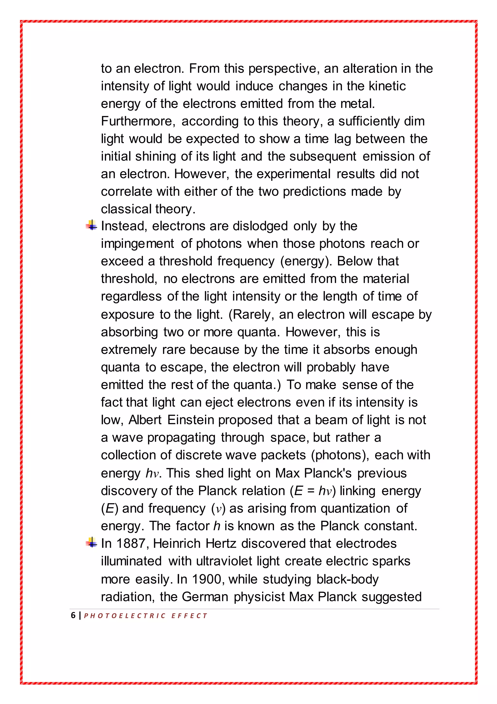
journal Annalen der Physik. His receiver
consisted of a coil with a spark gap,
where a spark would be seen upon
detection of electromagnetic waves. He
placed the apparatus in a darkened box to
see the spark better. However, he noticed
that the maximum spark length was
reduced when in the box. A glass panel
placed between the source of
electromagnetic waves and the receiver
absorbed ultraviolet radiation that
12 | P H O T O E L E C T R I C E F F E C T
assisted the electrons in jumping across
the gap. When removed, the spark length
would increase. He observed no decrease
in spark length when he replaced the glass
with quartz, as quartz does not absorb UV
radiation. Hertz concluded his months of
investigation and reported the results
obtained. He did not further pursue the
investigation of this effect.
The discovery by Hertz in 1887 that the incidence of ultra-violet light
on a spark gap facilitated the passage of the spark, led immediately to
a series of investigations by Hallwachs, Hoor, Righi and Stoletow on
the effect of light, and especially of ultra-violet light, on charged
bodies. It was proved by these investigations that a newly cleaned
surface of zinc, if charged with negative electricity, rapidly loses this
charge however small it may be when ultra-violet light falls upon the
surface; while if the surface is uncharged to begin with, it acquires a
positive charge when exposed to the light, the negative electrification
going out into the gas by which the metal is surrounded; this positive
electrification can be much increased by directing a strong air blast
against the surface. If however the zinc surface is positively electrified
it suffers no loss of charge when exposed to the light: this result has
been questioned, but a very careful examination of the phenomenon
by Elster and Geitel has shown that the loss observed under certain
circumstances is due to the discharge by the light reflected from the
zinc surface of negative electrification on neighbouring conductors
induced by the positive charge, the negative electricity under the
influence of the electric field moving up to the positively electrified
surface.
With regard to the Hertz effect, the researchers from the start showed
a great complexity of the phenomenon of photoelectric fatigue — that
is, the progressive diminution of the effect observed upon fresh
metallic surfaces. According to an important research by Wilhelm
Hallwachs, ozone played an important part in the phenomenon.
13 | P H O T O E L E C T R I C E F F E C T
However, other elements enter such as oxidation, the humidity, the
mode of polish of the surface, etc. It was at the time not even sure that
the fatigue is absent in a vacuum.
In the period from February 1888 and until
1891, a detailed analysis of photo effect
was performed by Aleksandr Stoletov with
results published in 6 works; four of them in
Comptes Rendus, one review in
Physikalische Revue (translated from
Russian), and the last work in Journal de
Physique. First, in these works Stoletov
invented a new experimental setup which
was more suitable for a quantitative
analysis of photo effect. Using this setup,
he discovered the direct proportionality between the intensity of light
and the induced photo electric current (the first law of photo effect or
Stoletov’s law). One of his other findings resulted from measurements
of the dependence of the intensity of the electric photo current on the
gas pressure, where he found the existence of an optimal gas
pressure Pm corresponding to a maximum photocurrent; this property
was used for a creation of solar cells.In 1899, J. J. Thomson
investigated ultraviolet light in Crookes tubes. Thomson deduced that
the ejected particles were the same as those previously found in the
cathode ray, later called electrons, which he called "corpuscles". In the
research, Thomson enclosed a metal plate (a cathode) in a vacuum
tube, and exposed it to high-frequency radiation. It was thought that
the oscillating electromagnetic fields caused the atoms' field to
resonate and, after reaching certain amplitude, caused a subatomic
"corpuscle" to be emitted, and current to be detected. The amount of
this current varied with the intensity and colour of the radiation. Larger
radiation intensity or frequency would produce more current.
14 | P H O T O E L E C T R I C E F F E C T
20TH CENTURY:
The discovery of the ionization of gases by ultra-violet light was made
by Philipp Lenard in 1900. As the effect was produced across several
centimeters of air and made very great positive and small negative
ions, it was natural to interpret the phenomenon, as did J. J. Thomson,
as a Hertz effect upon the solid or liquid particles present in the gas.
In 1902, Lenard observed that the energy of
individual emitted electrons increased with the
frequency (which is related to the colour) of the
light.
This appeared to be at odds with Maxwell's wave
theory of light, which predicted that the electron
energy would be proportional to the intensity of the
radiation.
Lenard observed the variation in electron energy
with light frequency using a powerful electric arc
lamp which enabled him to investigate large changes in intensity, and
that had sufficient power to enable him to investigate the variation of
potential with light frequency. His experiment directly measured
potentials, not electron kinetic energy: he found the electron energy by
relating it to the maximum stopping potential (voltage) in a phototube.
He found that the calculated maximum electron kinetic energy is
determined by the frequency of the light. For example, an increase in
frequency results in an increase in the maximum kinetic energy
calculated for an electron upon liberation – ultraviolet radiation would
require a higher applied stopping potential to stop current in a
phototube than blue light. However, Lenard's results were qualitative
15 | P H O T O E L E C T R I C E F F E C T
rather than quantitative because of the difficulty in performing the
experiments: the experiments needed to be done on freshly cut metal
so that the pure metal was observed, but it oxidized in a matter of
minutes even in the partial vacuums he used. The current emitted by
the surface was determined by the light's intensity, or brightness:
doubling the intensity of the light doubled the number of electrons
emitted from the surface.
The researches of Langevin and those of Eugene Bloch have shown
that the greater part of the Lenard effect is certainly due to this 'Hertz
effect'. The Lenard effect upon the gas[itself nevertheless does exist.
Refound by J. J. Thomson and then more decisively by Frederic
Palmer, Jr., it was studied and showed very different characteristics
than those at first attributed to it by Lenard.
In 1905, Albert Einstein solved this
apparent paradox by describing light
as composed of discrete quanta, now
called photons, rather than continuous
waves. Based upon Max Planck's
theory of black-bodyradiation, Einstein
theorized that the energy in each
quantum of light was equal to the
frequency multiplied by a constant,
later called Planck's constant. A
photon above a threshold frequency
has the required energy to eject a
single electron, creating the observed
effect. This discovery led to the
quantum revolution in physics and
earned Einstein the Nobel Prize in
Physics in 1921. By wave-particle
duality the effect can be analyzed
purely in terms of waves though not as
conveniently.
16 | P H O T O E L E C T R I C E F F E C T
Albert Einstein's mathematical description of how the photoelectric
effect was caused by absorption of quanta of light was in one of his
1905 papers, named "On a Heuristic Viewpoint Concerning the
Production and Transformation of Light". This paper proposed the
simple description of "light quanta", or photons, and showed how they
explained such phenomena as the photoelectric effect. His simple
explanation in terms of absorption of discrete quanta of light explained
the features of the phenomenon and the characteristic frequency.
The idea of light quanta began with Max Planck's published law of
black-body radiation ("On the Law of Distribution of Energy in the
Normal Spectrum") by assuming that Hertzian oscillators could only
exist at energies E proportional to the frequency f of the oscillator by E
= hf, where h is Planck's constant. By assuming that light actually
consisted of discrete energy packets, Einstein wrote an equation for
the photoelectric effect that agreed with experimental results. It
explained why the energy of photoelectrons was dependent only on
the frequency of the incident light and not on its intensity: a low-
intensity, the high-frequency source could supply a few high energy
photons, whereas a high-intensity, the low-frequency source would
supply no photons of sufficient individual energy to dislodge any
electrons.This was an enormous theoretical leap, but the concept was
strongly resisted at first because it contradicted the wave theory of
light that followed naturally from James Clerk Maxwell's equations for
electromagnetic behavior, and more generally, the assumption of
infinite divisibility of energy in physical systems. Even after
experiments showed that Einstein's equations for the photoelectric
effectwere accurate, resistance to the idea of photons continued since
it appeared to contradict Maxwell's equations, which were well
understood and verified.
Einstein's work predicted that the energy of individual ejected electrons
increases linearly with the frequency of the light. Perhaps surprisingly,
the precise relationship had not at that time been tested. By 1905 it
was known that the energy of photoelectrons increases with increasing
17 | P H O T O E L E C T R I C E F F E C T
frequency of incident light and is independent of the intensity of the
light. However, the manner of the increase was not experimentally
determined until 1914 when Robert Andrews Millikan showed that
Einstein's prediction was correct.
The photoelectric effecthelped to propelthe then-emerging concept of
wave–particle duality in the nature of light. Light simultaneously
possesses the characteristics of both waves and particles, each being
manifested according to the circumstances.The effect was impossible
to understand in terms of the classical wave description of light, as the
energy of the emitted electrons did not depend on the intensity of the
incident radiation. Classical theory predicted that the electrons would
'gather up' energy over a period of time, and then be emitted.
Hertz’s Observations
The phenomenon of photoelectric effectwas first discoveredby
Heinrich Hertz in
18 | P H O T O E L E C T R I C E F F E C T
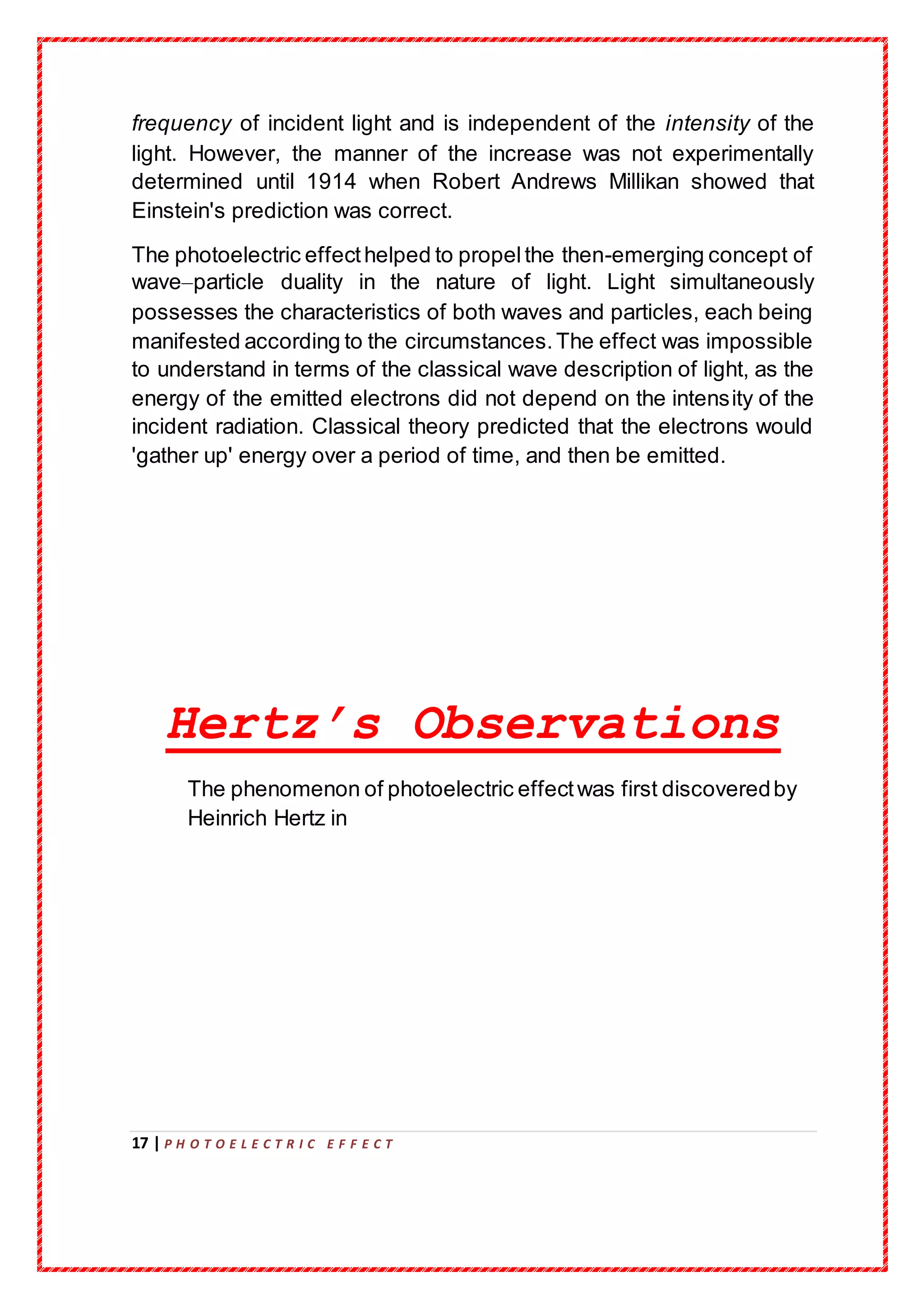
1887.While demonstrating the existence of electromagnetic waves,
Hertz found that the high voltage sparks passed across the metal
electrodesof the detectorloop more easily when the cathode was
illuminated by UV light from an arc lamp. The UV light falling on the
metal surface caused the emissionof negatively charged particles,
which are known as electrons, into the surrounding space and hence
enhanced the high voltage sparks.
19 | P H O T O E L E C T R I C E F F E C T
Hallwach’s and
Lenard’s Observations
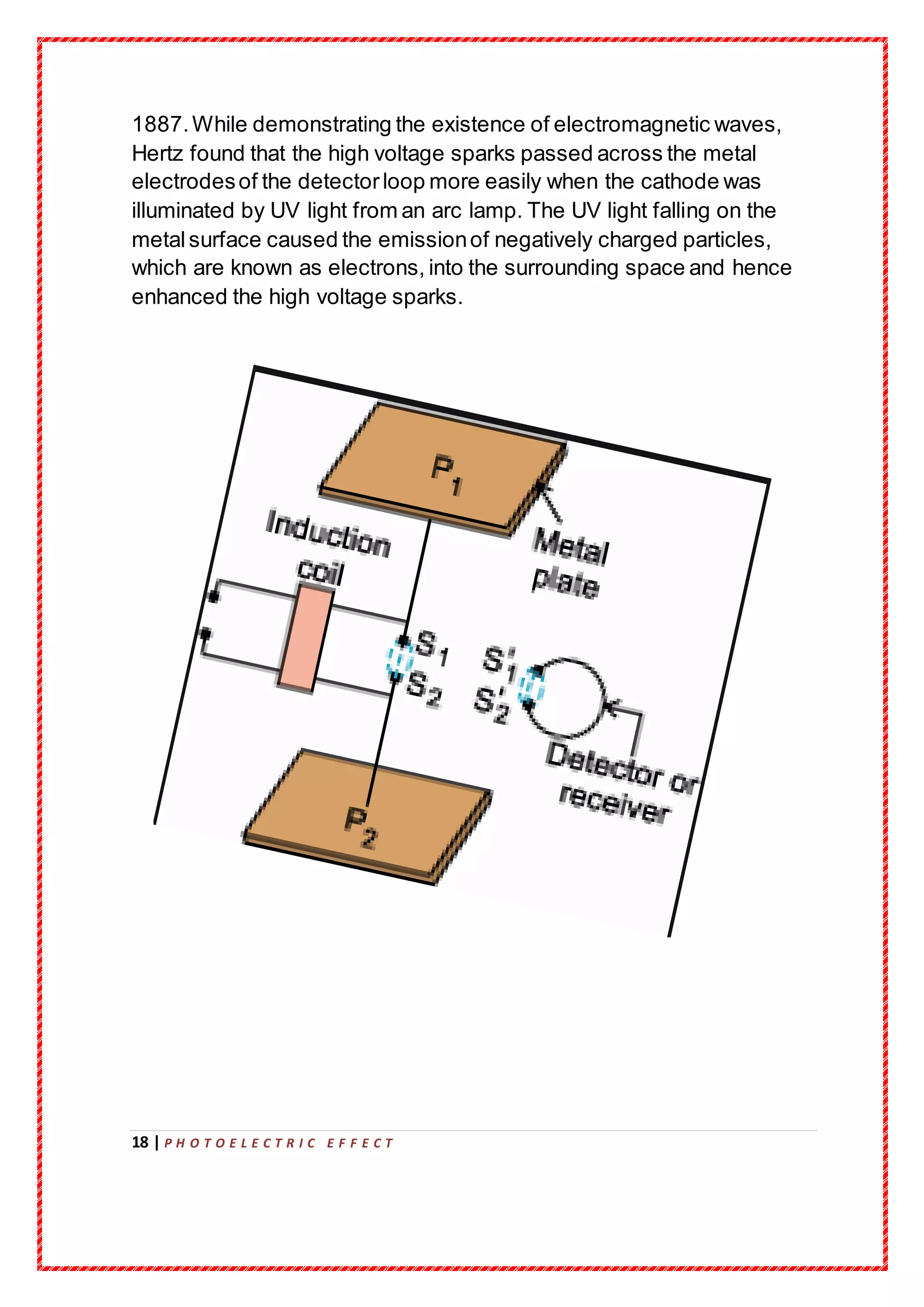
During the years 1886-1902, Wilhelm Hallwachs and Philipp Lenard
investigated the phenomenon of photoelectric emission in detail.
Hallwachs connected a zinc plate to an electroscope. He allowed UV
light to fall on a zinc plate. He observed that the zinc plate became: (i)
uncharged if initially negatively charged, (ii) positively charged if
initially uncharged, (iii) more positively charged if initially positively
charged. From these observations he concluded that some negatively
charged particles were emitted by the zinc plate when exposed to UV
light.
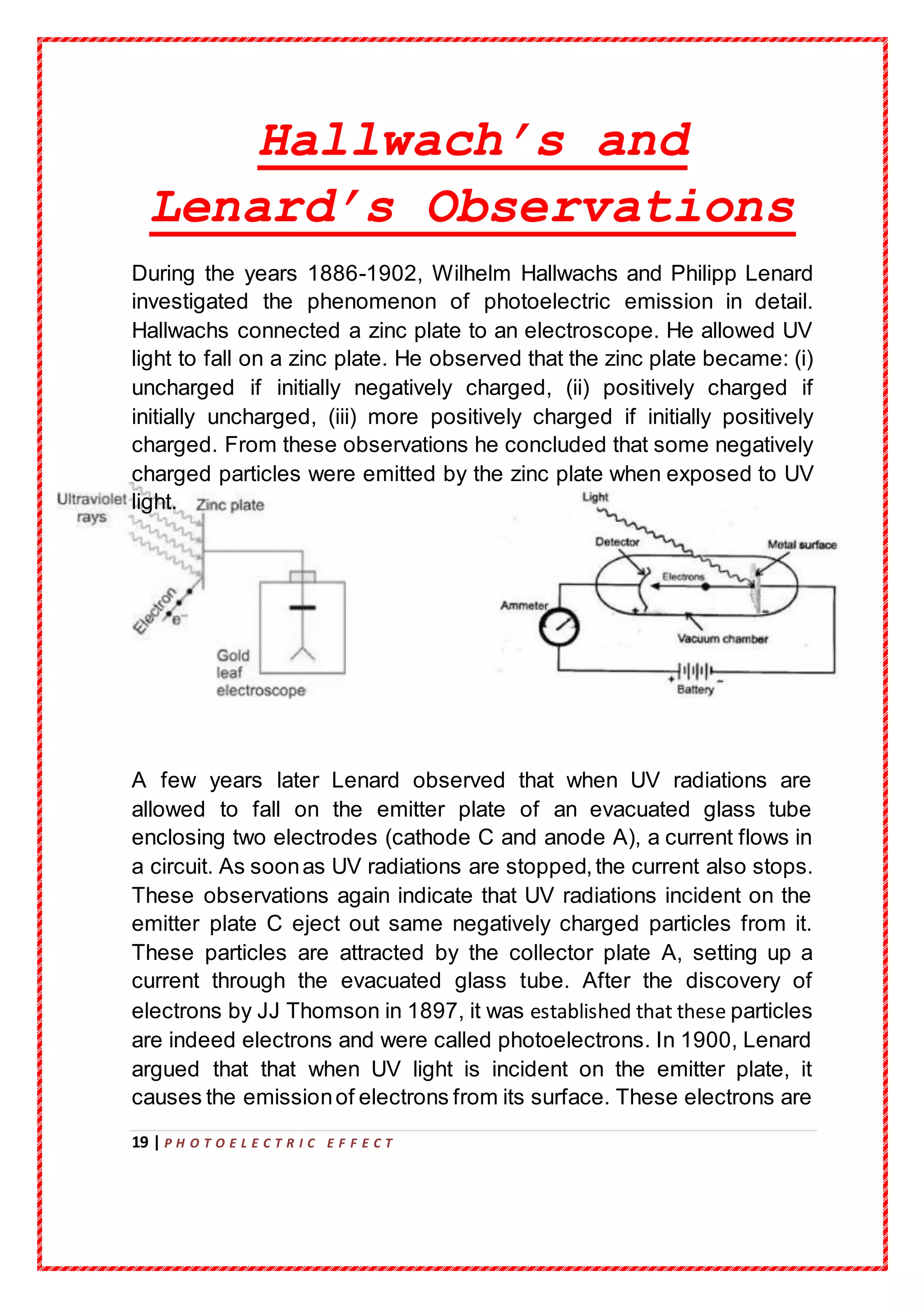
A few years later Lenard observed that when UV radiations are
allowed to fall on the emitter plate of an evacuated glass tube
enclosing two electrodes (cathode C and anode A), a current flows in
a circuit. As soonas UV radiations are stopped,the current also stops.
These observations again indicate that UV radiations incident on the
emitter plate C eject out same negatively charged particles from it.
These particles are attracted by the collector plate A, setting up a
current through the evacuated glass tube. After the discovery of
electrons by JJ Thomson in 1897, it was established that these particles
are indeed electrons and were called photoelectrons. In 1900, Lenard
argued that that when UV light is incident on the emitter plate, it
causes the emissionof electrons from its surface. These electrons are
20 | P H O T O E L E C T R I C E F F E C T
attracted by the positive collector plate so that the circuit is completed
and the current flows. This current was called Photoelectric current.
Hallwachs and Lenard also observed that when the frequency of the
incident light was less than the a certain minimum value, called the
threshold frequency, no photoelectrons were emitted at all.
Different substances emit photoelectrons only when exposed to
radiations of different frequencies. Alkali metals like Li, Na, K, Cs and
R barer highly photosensitive. They emit electrons even with visible
light. Metals like Zn, Cd, Mg, Al etc. respond only to UV light. X-rays
can eject electrons even from heavy metals.
21 | P H O T O E L E C T R I C E F F E C T
Experimental study of
photoelectric effect
An extensive study of photoelectric effectwas made by Lenard and RA
Millikan.
Figure depicts a schematic view
of the arrangement used for the
experimental study of the
photoelectric effect. It consists
of an evacuated glass/quartz
tube having a photosensitive
plate C and another metal plate
A. Monochromatic light from the
source S of sufficiently short
w
a
v
e
l
e
n
g
t
h
p
asses through the window W
and falls on the photosensitive
plate C (emitter). A transparent
22 | P H O T O E L E C T R I C E F F E C T
quartz window is sealed on to
the glass tube, which permits
ultraviolet radiation to pass
through it and irradiate the
photosensitive plate C. The
electrons are emitted by the
plate C and are collected by the
plate A (collector), by the
electric field created by the
battery. The battery maintains
the potential difference between
the platesC and A, that can be
varied. The polarity of the plates
C and A can be reversed by a
commutator. Thus, the plate A
can be maintained at a desired
positive or negative potential
with respect to emitter C. When
the collector plate A is positive
with respect to the emitter plate
C, the electrons are attracted to
it. The emission of electrons
causes flow of electric current in
the circuit. The potential
difference between the emitter
and collectorplates is measured
by a voltmeter (V) whereas the
resulting photo current flowing in
the circuit is measured by a
microammeter (µA). The
photoelectric current can be
increased or decreased by
varying the potential of collector
plate A with respect to the
emitter plate C. The intensity
23 | P H O T O E L E C T R I C E F F E C T
and frequency of the incident
light can be varied, as can the
potential difference V between
the emitter C and the collector
A.
We can use the experimental arrangement of Fig. to study the
variation of photocurrent with (a) intensity of radiation, (b) frequency of
incident radiation, (c) the potential difference betweenthe plates A and
C, and (d) the nature of the material of plate C. Light of different
frequencies can be used by putting appropriate coloured filter or
coloured glass in the path of light falling on the emitter C. The intensity
of light is varied by changing the distance of the light source from the
emitter.
Laws of photoelectric
emission
On the basis of the experimental results on photoelectric effect,
Lenard and Millikan gave the following laws of photoelectric emission:
24 | P H O T O E L E C T R I C E F F E C T
 For a given photosensitive material and frequencyof the incident
radiation, (Above the threshold frequency), the photoelectric
current is directly proportional to the intensity of light. The
saturation current is directly proportional to the intensity of
incident radiation.
 For a given photosensitive material, there exists a certain
minimum cut-off frequency below which no photoelectrons are
emitted, howsoever high is the intensity of incident radiation.
This frequency is called threshold frequency.
 Above the threshold frequency, the stopping potential or
equivalently the maximum kinetic energy of the photoelectrons is
directly proportional to the frequencyof the incident radiation, but
is independent of its intensity.
 The photoelectric emissionis an instantaneous process.The
time lag betweenthe incidence of light radiation and the
emissionof photoelectrons is very small, even less than 10-9
s.
25 | P H O T O E L E C T R I C E F F E C T
Failure of classical
wave theory to explain
photoelectric effect
According to the wave theory, light is an electromagnetic wave
consisting of electric and magnetic fields with continuous distribution of
energy over the region over which the wave extends. This wave
picture of light could not explain the basic features of light as explained
below;
1. According to wave theory, when a wavefront of light strikes a
metal surface, the free electrons at the surface absorb the
radiant energy continuously. Greater the intensity of incident
radiation, greater is the amplitudes of the electric and magnetic
felids, and greater is the energy density of the wave. Hence
higher intensity should liberate photoelectrons with kinetic
energy. But this is contrary to the experimental result that the
maximum kinetic energy of the photoelectrons does not depend
on the intensity of the incident radiation.
2. No matter what the frequency of the incident radiation is, a light
wave of sufficientintensity (over a sufficient time) should be able
to impart enough energy required to eject the electrons from the
metal surface. Thus the wave theory fails to explain the
existence of threshold frequency.
3. The energy of light wave is smoothly and evenly distributed
across its advancing wavefront. Each electron intercepts an
insignificantly small amount of this energy and so it should
require a finite time to escape from metal surface. But actually,
the emission is almost instantaneous.
26 | P H O T O E L E C T R I C E F F E C T
Einstein’s Theory
In 1905, Einstein explained photoelectric effect on the basis of
Planck’s quantum theory according to which radiation travels in the
form of discrete photons. The energy of each photon is hʋ, where h is
planck’s constant and ʋ is the frequency of light.
The main pointsof the Einstein’s Theoryof photoelectric effect
are;
1. Photoelectric emissionis the result of interaction of two particles-
one a photon of radiation and the other an electron of the
photosensitive metal.
2. The free electrons are bound within the surface of the metal due
to restraining forces
of the surface. The minimum energy required to liberate an
electron from the metal surface is called work function W0 of the
metal.
3. Each photon interacts with one electron.The energy hʋ of the
incident photon is used up in two parts;
a. A part of the energy of the photon is used in liberating the
electron from the metal surface, which is equal to the work
function of the metal.
b. The remaining energy of the photon is bused in imparting
kinetic energy to the ejected electron.
27 | P H O T O E L E C T R I C E F F E C T
4. Very few (<1%) photons, whose energies are greater than the
work function are capable of ejecting the photoelectrons.
By the conservation of energy,
Energy of the incident photon = maximum KE of photoelectron+ work
function
hʋ = mv2
max + W0
Kmax = mv2
max = hʋ - W0
If the incident photon is of threshold frequency ʋ0, then its energy hʋ0
is hujust sufficientfrom the metal surface and does not give it any
kinetic energy. So hʋ0 = W0. Hence,
Kmax = mv2
max = hʋ - hʋ0 = h(ʋ - ʋ0)
The above equation is called Einstein’sPhotoelectric Equation and
can be used to explain the laws of photoelectric effectas follows:
 Explanation of effect of intensity: the increase of intensity
means the increase in the number of photons striking the metal
surface per unit time. As each photon ejects only one electron,
so the number of ejected electrons increases with increase in
intensity of incident radiation.
 Explanation of thresholdfrequency: If v < v0 the frequency of
incident radiation is less than the threshold frequency, the KE of
photoelectrons becomes negative. This has no physical
meaning. So photoelectron emission does not occur below the
threshold frequency.
 Explanation of kineticenergy: If v > v0 then
Kmax = mv2
max α ʋ
i.e. above threshold frequency, the maximum kinetic energy of
the electrons increases linearly with increase in the intensity increases
only the number of incident photons and not their energy. Hence the
maximum kinetic energy of the photoelectrons is independentof the
intensity of incident radiation.
28 | P H O T O E L E C T R I C E F F E C T
 Explanation of time lag: photoelectric emissionis the
result of an elastic collision between a photon and an
electron. Thus the absorptionof energy from a photon by a
free electron inside the metal is a single event which
involves transfer of energy in one lump instead of
continuous absorptionof energy as in wave theory of light.
Hence there is no time lag between the incidence of a
photon and the emissionof a photoelectron.
Uses and Effects
PHOTOMULTIPLIERS:
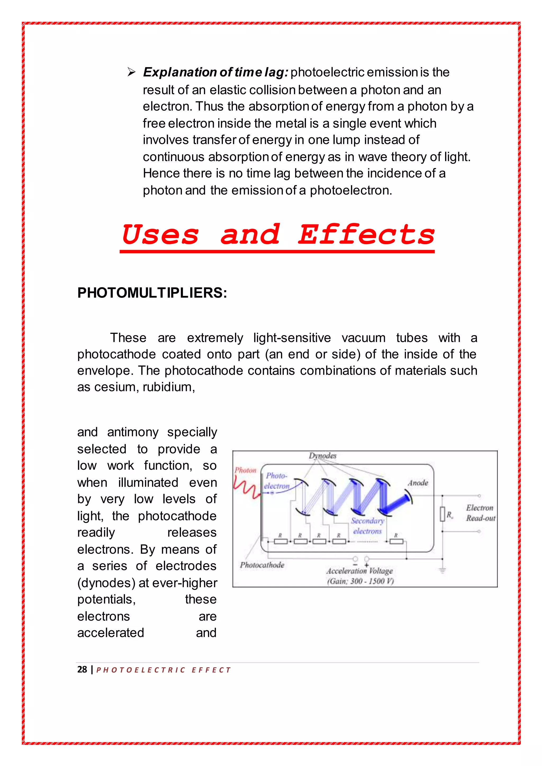
These are extremely light-sensitive vacuum tubes with a
photocathode coated onto part (an end or side) of the inside of the
envelope. The photocathode contains combinations of materials such
as cesium, rubidium,
and antimony specially
selected to provide a
low work function, so
when illuminated even
by very low levels of
light, the photocathode
readily releases
electrons. By means of
a series of electrodes
(dynodes) at ever-higher
potentials, these
electrons are
accelerated and
29 | P H O T O E L E C T R I C E F F E C T
substantially increased
in number
through secondaryemissionto provide a readily detectable output
current. Photomultipliers are still commonlyused wherever low levels
of light must be detected
IMAGE SENSORS:
Video camera tubes in the early days of television used the
photoelectric effect,forexample, Philo Farnsworth's "Image dissector"
used a screen charged by the photoelectric effectto transform an
optical image into a scanned electronic signal.
GOLD-LEAF ELECTROSCOPE:
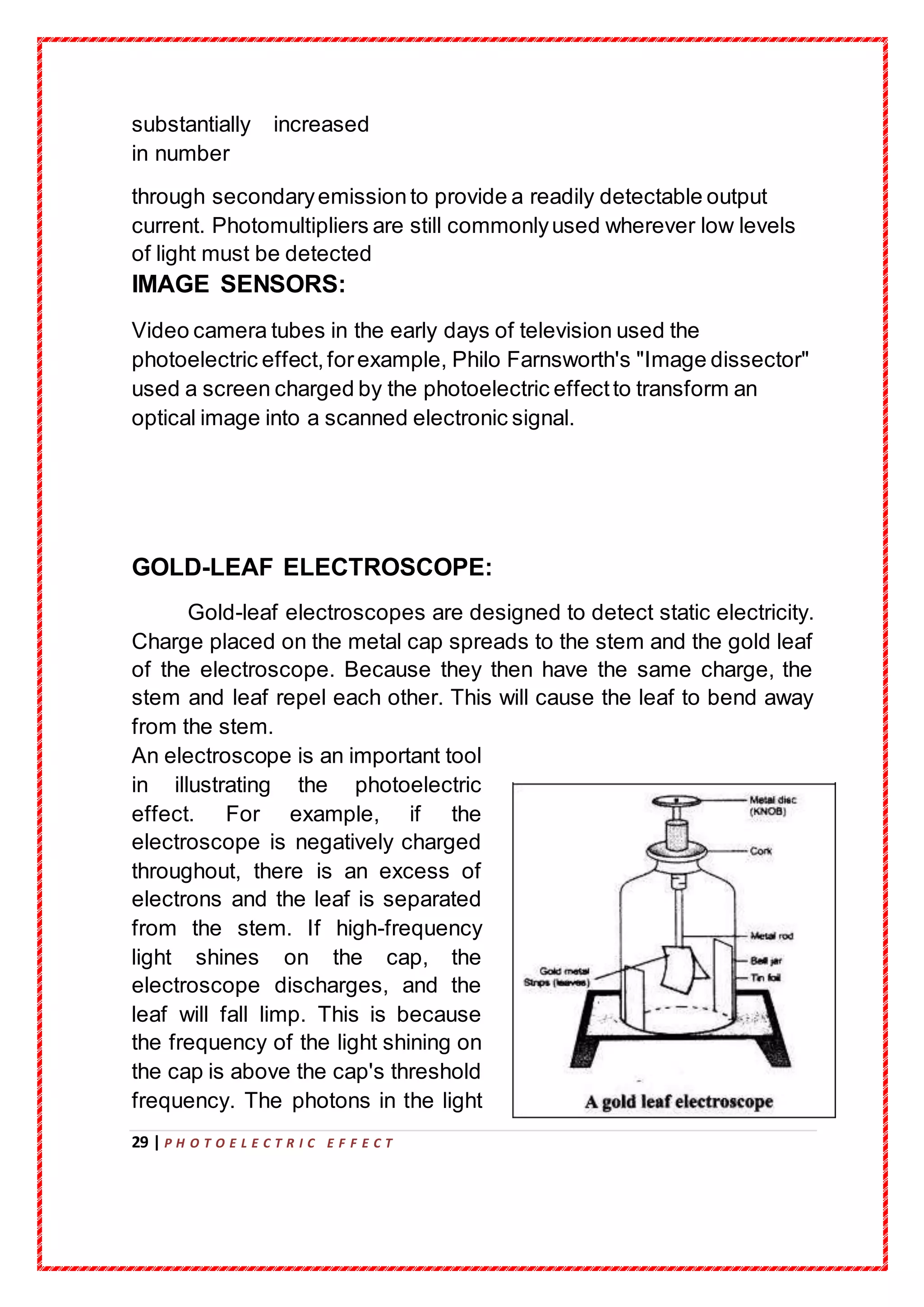
Gold-leaf electroscopes are designed to detect static electricity.
Charge placed on the metal cap spreads to the stem and the gold leaf
of the electroscope. Because they then have the same charge, the
stem and leaf repel each other. This will cause the leaf to bend away
from the stem.
An electroscope is an important tool
in illustrating the photoelectric
effect. For example, if the
electroscope is negatively charged
throughout, there is an excess of
electrons and the leaf is separated
from the stem. If high-frequency
light shines on the cap, the
electroscope discharges, and the
leaf will fall limp. This is because
the frequency of the light shining on
the cap is above the cap's threshold
frequency. The photons in the light
30 | P H O T O E L E C T R I C E F F E C T
have enough energy to liberate
electrons from the cap, reducing its
negative charge. This will discharge
a negatively charged electroscope
and further charge a positive
electroscope. However, if
the electromagnetic radiation hitting the metal cap does not have a
high enough frequency (its frequency is below the threshold value for
the cap), then the leaf will never discharge, no matter how long one
shines the low-frequency light at the cap.
PHOTOELECTRON SPECTROSCOPY:
Since the energy of the photoelectrons emitted is exactly the energy of
the incident photon minus the material's work function or binding
energy, the work function of a sample can be determined by
bombarding it with a monochromatic X-ray source or UV source, and
measuring the kinetic energy distribution of the electrons emitted.
Photoelectron spectroscopy is usually done in a high-vacuum
environment, since the electrons would be scattered by gas molecules
if they were present. However, some companies are now selling
products that allow photoemission in air. The light source can be a
laser, a discharge tube, or a synchrotron radiation source.
The concentric hemispherical analyzer is a typical electron
energy analyzer and uses an electric field to change the directions of
incident electrons, depending on their kinetic
31 | P H O T O E L E C T R I C E F F E C T
Bibliography
https://www.google.co.in/search
https://en.wikipedia.org/wiki/Photoelectric_effect
NCERT Physics Textbook
32 | P H O T O E L E C T R I C E F F E C T
New Simplified Physics by SL Arora


More Related Content

What's hot

Photoelectric effect and experimental setup
Photoelectric effect and experimental setupPhotoelectric effect and experimental setup
Photoelectric effect and experimental setupOmkar Rane
 
FARADAY LAW OF ELECTROMAGNETIC INDUCTION CLASS 12 PROJECT
FARADAY LAW OF ELECTROMAGNETIC INDUCTION CLASS 12 PROJECTFARADAY LAW OF ELECTROMAGNETIC INDUCTION CLASS 12 PROJECT
FARADAY LAW OF ELECTROMAGNETIC INDUCTION CLASS 12 PROJECTAjay Kumar
 
Photoelectric effect ppt
Photoelectric effect pptPhotoelectric effect ppt
Photoelectric effect pptRamkumar2112
 
Physics investigatory project
Physics investigatory projectPhysics investigatory project
Physics investigatory projectNIKHIL DWIVEDI
 
INVESTIGATORY PROJECT ON SEMICONDUCTOR by shivam jhade
INVESTIGATORY PROJECT ON SEMICONDUCTOR by shivam jhade INVESTIGATORY PROJECT ON SEMICONDUCTOR by shivam jhade
INVESTIGATORY PROJECT ON SEMICONDUCTOR by shivam jhade bhopal
 
Physics Investigatory Project Class 12
Physics Investigatory Project Class 12Physics Investigatory Project Class 12
Physics Investigatory Project Class 12Ayush Suman
 
Current Electricity Class 12 Part-1
Current Electricity Class 12 Part-1Current Electricity Class 12 Part-1
Current Electricity Class 12 Part-1Self-employed
 
Electromagnetic induction
Electromagnetic induction Electromagnetic induction
Electromagnetic induction Vishnu Prasad
 
CBSE Class XII Physics Investigatory Project
CBSE Class XII Physics Investigatory ProjectCBSE Class XII Physics Investigatory Project
CBSE Class XII Physics Investigatory ProjectVaibhav Kandwal
 
XII INVESTIGATORY PHYSICS PROJECT
XII INVESTIGATORY PHYSICS PROJECTXII INVESTIGATORY PHYSICS PROJECT
XII INVESTIGATORY PHYSICS PROJECTEr Shambhu Chauhan
 
Physics Investigatory Project Class 12
Physics Investigatory Project Class 12Physics Investigatory Project Class 12
Physics Investigatory Project Class 12Self-employed
 
Physics Investigatory Project
Physics Investigatory  ProjectPhysics Investigatory  Project
Physics Investigatory ProjectDIVYANSHU KUMAR
 
electromagnetic induction ( part 2 )
electromagnetic induction ( part 2 )electromagnetic induction ( part 2 )
electromagnetic induction ( part 2 )Priyanka Jakhar
 
Physics Investigatory - Electromagnetic Induction. CLASS XII
Physics Investigatory - Electromagnetic Induction.    CLASS XIIPhysics Investigatory - Electromagnetic Induction.    CLASS XII
Physics Investigatory - Electromagnetic Induction. CLASS XIIEligetiVishnu
 
project on electromagnetic induction
project on electromagnetic inductionproject on electromagnetic induction
project on electromagnetic inductionLovneesh kumar
 
Dual nature of radiation and matter class 12
Dual nature of radiation and matter class 12Dual nature of radiation and matter class 12
Dual nature of radiation and matter class 12Lovedeep Singh
 

What's hot (20)

Photoelectric effect and experimental setup
Photoelectric effect and experimental setupPhotoelectric effect and experimental setup
Photoelectric effect and experimental setup
 
FARADAY LAW OF ELECTROMAGNETIC INDUCTION CLASS 12 PROJECT
FARADAY LAW OF ELECTROMAGNETIC INDUCTION CLASS 12 PROJECTFARADAY LAW OF ELECTROMAGNETIC INDUCTION CLASS 12 PROJECT
FARADAY LAW OF ELECTROMAGNETIC INDUCTION CLASS 12 PROJECT
 
Photo electric effect
Photo electric effectPhoto electric effect
Photo electric effect
 
Photoelectric effect ppt
Photoelectric effect pptPhotoelectric effect ppt
Photoelectric effect ppt
 
Physics investigatory project
Physics investigatory projectPhysics investigatory project
Physics investigatory project
 
INVESTIGATORY PROJECT ON SEMICONDUCTOR by shivam jhade
INVESTIGATORY PROJECT ON SEMICONDUCTOR by shivam jhade INVESTIGATORY PROJECT ON SEMICONDUCTOR by shivam jhade
INVESTIGATORY PROJECT ON SEMICONDUCTOR by shivam jhade
 
Physics Investigatory Project Class 12
Physics Investigatory Project Class 12Physics Investigatory Project Class 12
Physics Investigatory Project Class 12
 
Current Electricity Class 12 Part-1
Current Electricity Class 12 Part-1Current Electricity Class 12 Part-1
Current Electricity Class 12 Part-1
 
Electromagnetic induction
Electromagnetic induction Electromagnetic induction
Electromagnetic induction
 
CBSE Class XII Physics Investigatory Project
CBSE Class XII Physics Investigatory ProjectCBSE Class XII Physics Investigatory Project
CBSE Class XII Physics Investigatory Project
 
XII INVESTIGATORY PHYSICS PROJECT
XII INVESTIGATORY PHYSICS PROJECTXII INVESTIGATORY PHYSICS PROJECT
XII INVESTIGATORY PHYSICS PROJECT
 
Physics Investigatory Project Class 12
Physics Investigatory Project Class 12Physics Investigatory Project Class 12
Physics Investigatory Project Class 12
 
Physics Investigatory Project
Physics Investigatory  ProjectPhysics Investigatory  Project
Physics Investigatory Project
 
electromagnetic induction ( part 2 )
electromagnetic induction ( part 2 )electromagnetic induction ( part 2 )
electromagnetic induction ( part 2 )
 
Transformer(Class 12 Investigatory Project)
Transformer(Class 12 Investigatory Project)Transformer(Class 12 Investigatory Project)
Transformer(Class 12 Investigatory Project)
 
Physics Project
Physics ProjectPhysics Project
Physics Project
 
Physics Investigatory - Electromagnetic Induction. CLASS XII
Physics Investigatory - Electromagnetic Induction.    CLASS XIIPhysics Investigatory - Electromagnetic Induction.    CLASS XII
Physics Investigatory - Electromagnetic Induction. CLASS XII
 
project on electromagnetic induction
project on electromagnetic inductionproject on electromagnetic induction
project on electromagnetic induction
 
Dual nature of radiation and matter class 12
Dual nature of radiation and matter class 12Dual nature of radiation and matter class 12
Dual nature of radiation and matter class 12
 
Physics investigatory project
Physics investigatory projectPhysics investigatory project
Physics investigatory project
 

Similar to THE PHOTOELECTRIC EFFECT !!!!!!

IB Physic Extended Essay
IB Physic Extended EssayIB Physic Extended Essay
IB Physic Extended EssayErtu?rul Akay
 
Particle Properties of Wave
Particle Properties of WaveParticle Properties of Wave
Particle Properties of WaveBicol University
 
341194430-Quantum-Physics.ppt
341194430-Quantum-Physics.ppt341194430-Quantum-Physics.ppt
341194430-Quantum-Physics.pptMadihaAhmed42
 
Chapter 2 structure of atom class 11
Chapter 2 structure of atom class 11Chapter 2 structure of atom class 11
Chapter 2 structure of atom class 11ritik
 
chapter2-structureofatom-.pdf
chapter2-structureofatom-.pdfchapter2-structureofatom-.pdf
chapter2-structureofatom-.pdfLUXMIKANTGIRI
 
Limitations OF Classical Physics and Birth Of Quantum Mechanics
Limitations OF Classical Physics and Birth Of Quantum MechanicsLimitations OF Classical Physics and Birth Of Quantum Mechanics
Limitations OF Classical Physics and Birth Of Quantum MechanicsCENTER FOR HIGH ENERGY PHYSICS
 
Subhadeep_BSPH101.pptx dsuyfgwf7ywidvweiufwetdfiuqefuhygedfiewgfi
Subhadeep_BSPH101.pptx dsuyfgwf7ywidvweiufwetdfiuqefuhygedfiewgfiSubhadeep_BSPH101.pptx dsuyfgwf7ywidvweiufwetdfiuqefuhygedfiewgfi
Subhadeep_BSPH101.pptx dsuyfgwf7ywidvweiufwetdfiuqefuhygedfiewgfiBirendraNathNandi
 
Photo electric effect 1
Photo electric effect 1Photo electric effect 1
Photo electric effect 1AnnaSrinivas2
 

Similar to THE PHOTOELECTRIC EFFECT !!!!!! (20)

Presentation laser
Presentation  laserPresentation  laser
Presentation laser
 
IB Physic Extended Essay
IB Physic Extended EssayIB Physic Extended Essay
IB Physic Extended Essay
 
Physics
PhysicsPhysics
Physics
 
Dual nature of radiation
Dual nature of radiationDual nature of radiation
Dual nature of radiation
 
CHAPTER 3 The Experimental Basis of Quantum Theory
CHAPTER 3The Experimental Basis of Quantum TheoryCHAPTER 3The Experimental Basis of Quantum Theory
CHAPTER 3 The Experimental Basis of Quantum Theory
 
Particle Properties of Wave
Particle Properties of WaveParticle Properties of Wave
Particle Properties of Wave
 
Modephy note4 1
Modephy note4 1Modephy note4 1
Modephy note4 1
 
Phot eleceffectphy4d
Phot eleceffectphy4dPhot eleceffectphy4d
Phot eleceffectphy4d
 
PHOTOELECTRIC EFFECT
PHOTOELECTRIC EFFECT PHOTOELECTRIC EFFECT
PHOTOELECTRIC EFFECT
 
341194430-Quantum-Physics.ppt
341194430-Quantum-Physics.ppt341194430-Quantum-Physics.ppt
341194430-Quantum-Physics.ppt
 
Chapter 2 structure of atom class 11
Chapter 2 structure of atom class 11Chapter 2 structure of atom class 11
Chapter 2 structure of atom class 11
 
13.1
13.113.1
13.1
 
chapter2-structureofatom-.pdf
chapter2-structureofatom-.pdfchapter2-structureofatom-.pdf
chapter2-structureofatom-.pdf
 
Limitations OF Classical Physics and Birth Of Quantum Mechanics
Limitations OF Classical Physics and Birth Of Quantum MechanicsLimitations OF Classical Physics and Birth Of Quantum Mechanics
Limitations OF Classical Physics and Birth Of Quantum Mechanics
 
Quantum mechanics S5
Quantum mechanics S5 Quantum mechanics S5
Quantum mechanics S5
 
Photo electric effect and compton
Photo electric effect and comptonPhoto electric effect and compton
Photo electric effect and compton
 
Particle Properties of Waves
Particle Properties of Waves Particle Properties of Waves
Particle Properties of Waves
 
lezione_3.ppt
lezione_3.pptlezione_3.ppt
lezione_3.ppt
 
Subhadeep_BSPH101.pptx dsuyfgwf7ywidvweiufwetdfiuqefuhygedfiewgfi
Subhadeep_BSPH101.pptx dsuyfgwf7ywidvweiufwetdfiuqefuhygedfiewgfiSubhadeep_BSPH101.pptx dsuyfgwf7ywidvweiufwetdfiuqefuhygedfiewgfi
Subhadeep_BSPH101.pptx dsuyfgwf7ywidvweiufwetdfiuqefuhygedfiewgfi
 
Photo electric effect 1
Photo electric effect 1Photo electric effect 1
Photo electric effect 1
 

Recently uploaded

GFP in rDNA Technology (Biotechnology).pptx
GFP in rDNA Technology (Biotechnology).pptxGFP in rDNA Technology (Biotechnology).pptx
GFP in rDNA Technology (Biotechnology).pptxAleenaTreesaSaji
 
Is RISC-V ready for HPC workload? Maybe?
Is RISC-V ready for HPC workload? Maybe?Is RISC-V ready for HPC workload? Maybe?
Is RISC-V ready for HPC workload? Maybe?Patrick Diehl
 
Hubble Asteroid Hunter III. Physical properties of newly found asteroids
Hubble Asteroid Hunter III. Physical properties of newly found asteroidsHubble Asteroid Hunter III. Physical properties of newly found asteroids
Hubble Asteroid Hunter III. Physical properties of newly found asteroidsSérgio Sacani
 
Call Girls in Munirka Delhi 💯Call Us 🔝8264348440🔝
Call Girls in Munirka Delhi 💯Call Us 🔝8264348440🔝Call Girls in Munirka Delhi 💯Call Us 🔝8264348440🔝
Call Girls in Munirka Delhi 💯Call Us 🔝8264348440🔝soniya singh
 
Luciferase in rDNA technology (biotechnology).pptx
Luciferase in rDNA technology (biotechnology).pptxLuciferase in rDNA technology (biotechnology).pptx
Luciferase in rDNA technology (biotechnology).pptxAleenaTreesaSaji
 
Unlocking the Potential: Deep dive into ocean of Ceramic Magnets.pptx
Unlocking  the Potential: Deep dive into ocean of Ceramic Magnets.pptxUnlocking  the Potential: Deep dive into ocean of Ceramic Magnets.pptx
Unlocking the Potential: Deep dive into ocean of Ceramic Magnets.pptxanandsmhk
 
A relative description on Sonoporation.pdf
A relative description on Sonoporation.pdfA relative description on Sonoporation.pdf
A relative description on Sonoporation.pdfnehabiju2046
 
Scheme-of-Work-Science-Stage-4 cambridge science.docx
Scheme-of-Work-Science-Stage-4 cambridge science.docxScheme-of-Work-Science-Stage-4 cambridge science.docx
Scheme-of-Work-Science-Stage-4 cambridge science.docxyaramohamed343013
 
Nanoparticles synthesis and characterization​ ​
Nanoparticles synthesis and characterization​  ​Nanoparticles synthesis and characterization​  ​
Nanoparticles synthesis and characterization​ ​kaibalyasahoo82800
 
Call Us ≽ 9953322196 ≼ Call Girls In Mukherjee Nagar(Delhi) |
Call Us ≽ 9953322196 ≼ Call Girls In Mukherjee Nagar(Delhi) |Call Us ≽ 9953322196 ≼ Call Girls In Mukherjee Nagar(Delhi) |
Call Us ≽ 9953322196 ≼ Call Girls In Mukherjee Nagar(Delhi) |aasikanpl
 
Traditional Agroforestry System in India- Shifting Cultivation, Taungya, Home...
Traditional Agroforestry System in India- Shifting Cultivation, Taungya, Home...Traditional Agroforestry System in India- Shifting Cultivation, Taungya, Home...
Traditional Agroforestry System in India- Shifting Cultivation, Taungya, Home...jana861314
 
Spermiogenesis or Spermateleosis or metamorphosis of spermatid
Spermiogenesis or Spermateleosis or metamorphosis of spermatidSpermiogenesis or Spermateleosis or metamorphosis of spermatid
Spermiogenesis or Spermateleosis or metamorphosis of spermatidSarthak Sekhar Mondal
 
Biopesticide (2).pptx .This slides helps to know the different types of biop...
Biopesticide (2).pptx  .This slides helps to know the different types of biop...Biopesticide (2).pptx  .This slides helps to know the different types of biop...
Biopesticide (2).pptx .This slides helps to know the different types of biop...RohitNehra6
 
Cultivation of KODO MILLET . made by Ghanshyam pptx
Cultivation of KODO MILLET . made by Ghanshyam pptxCultivation of KODO MILLET . made by Ghanshyam pptx
Cultivation of KODO MILLET . made by Ghanshyam pptxpradhanghanshyam7136
 
SOLUBLE PATTERN RECOGNITION RECEPTORS.pptx
SOLUBLE PATTERN RECOGNITION RECEPTORS.pptxSOLUBLE PATTERN RECOGNITION RECEPTORS.pptx
SOLUBLE PATTERN RECOGNITION RECEPTORS.pptxkessiyaTpeter
 
Animal Communication- Auditory and Visual.pptx
Animal Communication- Auditory and Visual.pptxAnimal Communication- Auditory and Visual.pptx
Animal Communication- Auditory and Visual.pptxUmerFayaz5
 
Stunning ➥8448380779▻ Call Girls In Panchshil Enclave Delhi NCR
Stunning ➥8448380779▻ Call Girls In Panchshil Enclave Delhi NCRStunning ➥8448380779▻ Call Girls In Panchshil Enclave Delhi NCR
Stunning ➥8448380779▻ Call Girls In Panchshil Enclave Delhi NCRDelhi Call girls
 
G9 Science Q4- Week 1-2 Projectile Motion.ppt
G9 Science Q4- Week 1-2 Projectile Motion.pptG9 Science Q4- Week 1-2 Projectile Motion.ppt
G9 Science Q4- Week 1-2 Projectile Motion.pptMAESTRELLAMesa2
 

Recently uploaded (20)

GFP in rDNA Technology (Biotechnology).pptx
GFP in rDNA Technology (Biotechnology).pptxGFP in rDNA Technology (Biotechnology).pptx
GFP in rDNA Technology (Biotechnology).pptx
 
The Philosophy of Science
The Philosophy of ScienceThe Philosophy of Science
The Philosophy of Science
 
Is RISC-V ready for HPC workload? Maybe?
Is RISC-V ready for HPC workload? Maybe?Is RISC-V ready for HPC workload? Maybe?
Is RISC-V ready for HPC workload? Maybe?
 
Hubble Asteroid Hunter III. Physical properties of newly found asteroids
Hubble Asteroid Hunter III. Physical properties of newly found asteroidsHubble Asteroid Hunter III. Physical properties of newly found asteroids
Hubble Asteroid Hunter III. Physical properties of newly found asteroids
 
Call Girls in Munirka Delhi 💯Call Us 🔝8264348440🔝
Call Girls in Munirka Delhi 💯Call Us 🔝8264348440🔝Call Girls in Munirka Delhi 💯Call Us 🔝8264348440🔝
Call Girls in Munirka Delhi 💯Call Us 🔝8264348440🔝
 
Luciferase in rDNA technology (biotechnology).pptx
Luciferase in rDNA technology (biotechnology).pptxLuciferase in rDNA technology (biotechnology).pptx
Luciferase in rDNA technology (biotechnology).pptx
 
Unlocking the Potential: Deep dive into ocean of Ceramic Magnets.pptx
Unlocking  the Potential: Deep dive into ocean of Ceramic Magnets.pptxUnlocking  the Potential: Deep dive into ocean of Ceramic Magnets.pptx
Unlocking the Potential: Deep dive into ocean of Ceramic Magnets.pptx
 
A relative description on Sonoporation.pdf
A relative description on Sonoporation.pdfA relative description on Sonoporation.pdf
A relative description on Sonoporation.pdf
 
Scheme-of-Work-Science-Stage-4 cambridge science.docx
Scheme-of-Work-Science-Stage-4 cambridge science.docxScheme-of-Work-Science-Stage-4 cambridge science.docx
Scheme-of-Work-Science-Stage-4 cambridge science.docx
 
Nanoparticles synthesis and characterization​ ​
Nanoparticles synthesis and characterization​  ​Nanoparticles synthesis and characterization​  ​
Nanoparticles synthesis and characterization​ ​
 
Call Us ≽ 9953322196 ≼ Call Girls In Mukherjee Nagar(Delhi) |
Call Us ≽ 9953322196 ≼ Call Girls In Mukherjee Nagar(Delhi) |Call Us ≽ 9953322196 ≼ Call Girls In Mukherjee Nagar(Delhi) |
Call Us ≽ 9953322196 ≼ Call Girls In Mukherjee Nagar(Delhi) |
 
Traditional Agroforestry System in India- Shifting Cultivation, Taungya, Home...
Traditional Agroforestry System in India- Shifting Cultivation, Taungya, Home...Traditional Agroforestry System in India- Shifting Cultivation, Taungya, Home...
Traditional Agroforestry System in India- Shifting Cultivation, Taungya, Home...
 
Spermiogenesis or Spermateleosis or metamorphosis of spermatid
Spermiogenesis or Spermateleosis or metamorphosis of spermatidSpermiogenesis or Spermateleosis or metamorphosis of spermatid
Spermiogenesis or Spermateleosis or metamorphosis of spermatid
 
Biopesticide (2).pptx .This slides helps to know the different types of biop...
Biopesticide (2).pptx  .This slides helps to know the different types of biop...Biopesticide (2).pptx  .This slides helps to know the different types of biop...
Biopesticide (2).pptx .This slides helps to know the different types of biop...
 
Cultivation of KODO MILLET . made by Ghanshyam pptx
Cultivation of KODO MILLET . made by Ghanshyam pptxCultivation of KODO MILLET . made by Ghanshyam pptx
Cultivation of KODO MILLET . made by Ghanshyam pptx
 
SOLUBLE PATTERN RECOGNITION RECEPTORS.pptx
SOLUBLE PATTERN RECOGNITION RECEPTORS.pptxSOLUBLE PATTERN RECOGNITION RECEPTORS.pptx
SOLUBLE PATTERN RECOGNITION RECEPTORS.pptx
 
Engler and Prantl system of classification in plant taxonomy
Engler and Prantl system of classification in plant taxonomyEngler and Prantl system of classification in plant taxonomy
Engler and Prantl system of classification in plant taxonomy
 
Animal Communication- Auditory and Visual.pptx
Animal Communication- Auditory and Visual.pptxAnimal Communication- Auditory and Visual.pptx
Animal Communication- Auditory and Visual.pptx
 
Stunning ➥8448380779▻ Call Girls In Panchshil Enclave Delhi NCR
Stunning ➥8448380779▻ Call Girls In Panchshil Enclave Delhi NCRStunning ➥8448380779▻ Call Girls In Panchshil Enclave Delhi NCR
Stunning ➥8448380779▻ Call Girls In Panchshil Enclave Delhi NCR
 
G9 Science Q4- Week 1-2 Projectile Motion.ppt
G9 Science Q4- Week 1-2 Projectile Motion.pptG9 Science Q4- Week 1-2 Projectile Motion.ppt
G9 Science Q4- Week 1-2 Projectile Motion.ppt
 

THE PHOTOELECTRIC EFFECT !!!!!!

  • 1. RMK SENIOR SECONDARY SCHOOL THIRUVERKADU, CHENNAI-77 ACADEMIC YEAR: 2019-20 Project submitted to the Central Board of Secondary Education (CBSE) in partial fulfilment for the requirement of All India Senior School Certificate Examination (AISSCE) 2019-’20, Department of physics. TOPIC: PREPARATION OF A MICROSCOPE BY NAME: D.YASHWANTH REG.NO: ……………………………………
  • 2. 1 | P H O T O E L E C T R I C E F F E C T GUIDED BY Mr. J.Mariappan RMK SENIOR SECONDARY SCHOOL THIRUVERKADU, CHENNAI-77 BONAFIDE CERTIFICATE Certified to be the bonafide record of the project work done by REG.NO:- of class XII in senior physics laboratory during the academic year 2019-20. TEACHER IN-CHARGE Submitted for all India Senior Secondary Practical Physics Examination held on . INTERNAL EXAMINER EXTERNAL EXAMINER
  • 3. 2 | P H O T O E L E C T R I C E F F E C T ACKNOWLEDGEMENT It is customary for me to acknowledgethe contributions and suggestions received from various sources. First of all I would like to thank god almighty for giving me wisdom and knowledge to showcase my talent. I am very thankful to our PrincipalMrs. Sudha Malini for giving me the golden opportunityto do this wonderful project. I wish to acknowledgethe tremendousamount of help received from my Physics Teacher Mr J.Mariaapan,without whose help and encouragement it would not have been possible for me to complete this project. I wish to express my gratitude to all non-teaching staff who helped me to complete my project. Whatever words I choose cannot sufficiently express my deep sense of gratitude towards my parents for their constant understanding, assistance, inspirationandmoral support in completing this project.
  • 4. 3 | P H O T O E L E C T R I C E F F E C T I would also like to acknowledge my thanks to my friends for their valuablesuggestions and timely help. PHOTOELEC TRIC
  • 5. 4 | P H O T O E L E C T R I C E F F E C T EFFECT BRAINED BY: S.HITESH BORHA CONTENT INTRODUCTION HISTORY Hertz’s Observations Hallwach’s and Lenard’s Observations
  • 6. 5 | P H O T O E L E C T R I C E F F E C T Experimental study of photoelectric effect Laws of photoelectric emission Failure of classical wave theory to explain photoelectric effect Einstein’s Theory Uses and Effects Bibliography INTRODUCTION The photoelectric effect is the emission of electrons or other free carriers when light shines on a material. Electrons emitted in this manner can be called photo electrons. This phenomenon is commonly studied in electronic physics, as well as in fields of chemistry, such as quantum chemistry or electrochemistry. According to classical electromagnetic theory, this effect can be attributed to the transfer of energy from the light
  • 7. 6 | P H O T O E L E C T R I C E F F E C T to an electron. From this perspective, an alteration in the intensity of light would induce changes in the kinetic energy of the electrons emitted from the metal. Furthermore, according to this theory, a sufficiently dim light would be expected to show a time lag between the initial shining of its light and the subsequent emission of an electron. However, the experimental results did not correlate with either of the two predictions made by classical theory. Instead, electrons are dislodged only by the impingement of photons when those photons reach or exceed a threshold frequency (energy). Below that threshold, no electrons are emitted from the material regardless of the light intensity or the length of time of exposure to the light. (Rarely, an electron will escape by absorbing two or more quanta. However, this is extremely rare because by the time it absorbs enough quanta to escape, the electron will probably have emitted the rest of the quanta.) To make sense of the fact that light can eject electrons even if its intensity is low, Albert Einstein proposed that a beam of light is not a wave propagating through space, but rather a collection of discrete wave packets (photons), each with energy hν. This shed light on Max Planck's previous discovery of the Planck relation (E = hν) linking energy (E) and frequency (ν) as arising from quantization of energy. The factor h is known as the Planck constant. In 1887, Heinrich Hertz discovered that electrodes illuminated with ultraviolet light create electric sparks more easily. In 1900, while studying black-body radiation, the German physicist Max Planck suggested
  • 8. 7 | P H O T O E L E C T R I C E F F E C T that the energy carried by electromagnetic waves could only be released in "packets" of energy. In 1905, Albert Einstein published a paper advancing the hypothesis that light energy is carried in discrete quantized packets to explain experimental data from the photoelectric effect. This model contributed to the development of quantum mechanics. In 1914, Millikan's Experiment supported Einstein's model of the photoelectric effect. Einstein was awarded the Nobel Prize in 1921 for "his discovery of the law of the photoelectric effect", and Robert Millikan was awarded the Nobel Prize in 1923 for "his work on the elementary charge of electricity and on the photoelectric effect". The photoelectric effect requires photons with energies approaching zero (in the case of negative electron affinity) to over 1 MeV for core electrons in elements with a high atomic number. Emission of conduction electrons from typical metals usually requires a few electron-volts, corresponding to short-wavelength visible or ultraviolet light. Study of the photoelectric effect led to important steps in understanding the quantum nature of light and electrons and influenced the formation of the concept of wave–particle duality. Other phenomena where light affects the movement of electric charges include the photoconductive effect (also known as photoconductivity or photo resistivity), the photovoltaic effect, and the photo electrochemical effect.
  • 9. 8 | P H O T O E L E C T R I C E F F E C T Photoemission can occur from any material, but it is most easily observable from metals or other conductors because the process produces a charge imbalance, and if this charge imbalance is not neutralized by current flow (enabled by conductivity), the potential barrier to emissionincreases until the emission current ceases. It is also usual to have the emitting surface in a vacuum, since gases impede the flow of photoelectrons and make them difficult to observe.Additionally, the energy barrier to photoemission is usually increased by thin oxide layers on metal surfaces if the metal has been exposed to oxygen, so most practical experiments and devices based on the photoelectric effect use clean metal surfaces in a vacuum. When the photoelectron is emitted into a solid rather than into a vacuum, the term internal photoemission is often used, and emissioninto a vacuum distinguished as external photoemission.
  • 10. 9 | P H O T O E L E C T R I C E F F E C T
  • 11. 10 | P H O T O E L E C T R I C E F F E C T HISTORY When a surface is exposed to electromagnetic radiation above a certain threshold frequency (typically visible light for alkali metals, near ultraviolet for other metals, and extreme ultraviolet for non-metals), the radiation is absorbed and electrons are emitted. Light, and especially ultra-violet light, discharges negatively electrified bodies with the production of rays of the same nature as cathode rays. Under certain circumstances it can directly ionize gases. The first of these phenomena was discovered by Hertz and Hallwachs in 1887. The second was announced first by Philipp Lenard in 1900. The ultra-violet light to produce these effects may be obtained from an arc lamp, or by burning magnesium, or by sparking with an induction coil between zinc or cadmium terminals, the light from which is very rich in ultra-violet rays. Sunlight is not rich in ultra-violet rays, as these have been absorbed by the atmosphere, and it does not produce nearly so large an effect as the arc-light. Many substances besides metals discharge negative electricity under the action of ultraviolet light: lists of these substances will be found in papers by G. C. Schmidt and O. Knoblauch.
  • 12. 11 | P H O T O E L E C T R I C E F F E C T 19TH CENTURY: In 1839, Alexandre Edmond Becquerel discovered the photovoltaic effect while studying the effect of light on electrolytic cells. Though not equivalent to the photoelectric effect, his work on photovoltaic was instrumental in showing a strong relationship between light and electronic properties of materials. In 1873, Willoughby Smith discovered photoconductivity in selenium while testing the metal for its high resistance properties in conjunction with his work involving submarine telegraph cables. Johann Elster (1854–1920) and Hans Geitel (1855–1923), students in Heidelberg, developed the first practical photoelectric cells that could be used to measure the intensity of light. Elster and Geitel had investigated with great success the effects produced by light on electrified bodies. In 1887, Heinrich Hertz observed the photoelectric effect and the production and reception of electromagnetic waves. He published these observations in the journal Annalen der Physik. His receiver consisted of a coil with a spark gap, where a spark would be seen upon detection of electromagnetic waves. He placed the apparatus in a darkened box to see the spark better. However, he noticed that the maximum spark length was reduced when in the box. A glass panel placed between the source of electromagnetic waves and the receiver absorbed ultraviolet radiation that
  • 13. 12 | P H O T O E L E C T R I C E F F E C T assisted the electrons in jumping across the gap. When removed, the spark length would increase. He observed no decrease in spark length when he replaced the glass with quartz, as quartz does not absorb UV radiation. Hertz concluded his months of investigation and reported the results obtained. He did not further pursue the investigation of this effect. The discovery by Hertz in 1887 that the incidence of ultra-violet light on a spark gap facilitated the passage of the spark, led immediately to a series of investigations by Hallwachs, Hoor, Righi and Stoletow on the effect of light, and especially of ultra-violet light, on charged bodies. It was proved by these investigations that a newly cleaned surface of zinc, if charged with negative electricity, rapidly loses this charge however small it may be when ultra-violet light falls upon the surface; while if the surface is uncharged to begin with, it acquires a positive charge when exposed to the light, the negative electrification going out into the gas by which the metal is surrounded; this positive electrification can be much increased by directing a strong air blast against the surface. If however the zinc surface is positively electrified it suffers no loss of charge when exposed to the light: this result has been questioned, but a very careful examination of the phenomenon by Elster and Geitel has shown that the loss observed under certain circumstances is due to the discharge by the light reflected from the zinc surface of negative electrification on neighbouring conductors induced by the positive charge, the negative electricity under the influence of the electric field moving up to the positively electrified surface. With regard to the Hertz effect, the researchers from the start showed a great complexity of the phenomenon of photoelectric fatigue — that is, the progressive diminution of the effect observed upon fresh metallic surfaces. According to an important research by Wilhelm Hallwachs, ozone played an important part in the phenomenon.
  • 14. 13 | P H O T O E L E C T R I C E F F E C T However, other elements enter such as oxidation, the humidity, the mode of polish of the surface, etc. It was at the time not even sure that the fatigue is absent in a vacuum. In the period from February 1888 and until 1891, a detailed analysis of photo effect was performed by Aleksandr Stoletov with results published in 6 works; four of them in Comptes Rendus, one review in Physikalische Revue (translated from Russian), and the last work in Journal de Physique. First, in these works Stoletov invented a new experimental setup which was more suitable for a quantitative analysis of photo effect. Using this setup, he discovered the direct proportionality between the intensity of light and the induced photo electric current (the first law of photo effect or Stoletov’s law). One of his other findings resulted from measurements of the dependence of the intensity of the electric photo current on the gas pressure, where he found the existence of an optimal gas pressure Pm corresponding to a maximum photocurrent; this property was used for a creation of solar cells.In 1899, J. J. Thomson investigated ultraviolet light in Crookes tubes. Thomson deduced that the ejected particles were the same as those previously found in the cathode ray, later called electrons, which he called "corpuscles". In the research, Thomson enclosed a metal plate (a cathode) in a vacuum tube, and exposed it to high-frequency radiation. It was thought that the oscillating electromagnetic fields caused the atoms' field to resonate and, after reaching certain amplitude, caused a subatomic "corpuscle" to be emitted, and current to be detected. The amount of this current varied with the intensity and colour of the radiation. Larger radiation intensity or frequency would produce more current.
  • 15. 14 | P H O T O E L E C T R I C E F F E C T 20TH CENTURY: The discovery of the ionization of gases by ultra-violet light was made by Philipp Lenard in 1900. As the effect was produced across several centimeters of air and made very great positive and small negative ions, it was natural to interpret the phenomenon, as did J. J. Thomson, as a Hertz effect upon the solid or liquid particles present in the gas. In 1902, Lenard observed that the energy of individual emitted electrons increased with the frequency (which is related to the colour) of the light. This appeared to be at odds with Maxwell's wave theory of light, which predicted that the electron energy would be proportional to the intensity of the radiation. Lenard observed the variation in electron energy with light frequency using a powerful electric arc lamp which enabled him to investigate large changes in intensity, and that had sufficient power to enable him to investigate the variation of potential with light frequency. His experiment directly measured potentials, not electron kinetic energy: he found the electron energy by relating it to the maximum stopping potential (voltage) in a phototube. He found that the calculated maximum electron kinetic energy is determined by the frequency of the light. For example, an increase in frequency results in an increase in the maximum kinetic energy calculated for an electron upon liberation – ultraviolet radiation would require a higher applied stopping potential to stop current in a phototube than blue light. However, Lenard's results were qualitative
  • 16. 15 | P H O T O E L E C T R I C E F F E C T rather than quantitative because of the difficulty in performing the experiments: the experiments needed to be done on freshly cut metal so that the pure metal was observed, but it oxidized in a matter of minutes even in the partial vacuums he used. The current emitted by the surface was determined by the light's intensity, or brightness: doubling the intensity of the light doubled the number of electrons emitted from the surface. The researches of Langevin and those of Eugene Bloch have shown that the greater part of the Lenard effect is certainly due to this 'Hertz effect'. The Lenard effect upon the gas[itself nevertheless does exist. Refound by J. J. Thomson and then more decisively by Frederic Palmer, Jr., it was studied and showed very different characteristics than those at first attributed to it by Lenard. In 1905, Albert Einstein solved this apparent paradox by describing light as composed of discrete quanta, now called photons, rather than continuous waves. Based upon Max Planck's theory of black-bodyradiation, Einstein theorized that the energy in each quantum of light was equal to the frequency multiplied by a constant, later called Planck's constant. A photon above a threshold frequency has the required energy to eject a single electron, creating the observed effect. This discovery led to the quantum revolution in physics and earned Einstein the Nobel Prize in Physics in 1921. By wave-particle duality the effect can be analyzed purely in terms of waves though not as conveniently.
  • 17. 16 | P H O T O E L E C T R I C E F F E C T Albert Einstein's mathematical description of how the photoelectric effect was caused by absorption of quanta of light was in one of his 1905 papers, named "On a Heuristic Viewpoint Concerning the Production and Transformation of Light". This paper proposed the simple description of "light quanta", or photons, and showed how they explained such phenomena as the photoelectric effect. His simple explanation in terms of absorption of discrete quanta of light explained the features of the phenomenon and the characteristic frequency. The idea of light quanta began with Max Planck's published law of black-body radiation ("On the Law of Distribution of Energy in the Normal Spectrum") by assuming that Hertzian oscillators could only exist at energies E proportional to the frequency f of the oscillator by E = hf, where h is Planck's constant. By assuming that light actually consisted of discrete energy packets, Einstein wrote an equation for the photoelectric effect that agreed with experimental results. It explained why the energy of photoelectrons was dependent only on the frequency of the incident light and not on its intensity: a low- intensity, the high-frequency source could supply a few high energy photons, whereas a high-intensity, the low-frequency source would supply no photons of sufficient individual energy to dislodge any electrons.This was an enormous theoretical leap, but the concept was strongly resisted at first because it contradicted the wave theory of light that followed naturally from James Clerk Maxwell's equations for electromagnetic behavior, and more generally, the assumption of infinite divisibility of energy in physical systems. Even after experiments showed that Einstein's equations for the photoelectric effectwere accurate, resistance to the idea of photons continued since it appeared to contradict Maxwell's equations, which were well understood and verified. Einstein's work predicted that the energy of individual ejected electrons increases linearly with the frequency of the light. Perhaps surprisingly, the precise relationship had not at that time been tested. By 1905 it was known that the energy of photoelectrons increases with increasing
  • 18. 17 | P H O T O E L E C T R I C E F F E C T frequency of incident light and is independent of the intensity of the light. However, the manner of the increase was not experimentally determined until 1914 when Robert Andrews Millikan showed that Einstein's prediction was correct. The photoelectric effecthelped to propelthe then-emerging concept of wave–particle duality in the nature of light. Light simultaneously possesses the characteristics of both waves and particles, each being manifested according to the circumstances.The effect was impossible to understand in terms of the classical wave description of light, as the energy of the emitted electrons did not depend on the intensity of the incident radiation. Classical theory predicted that the electrons would 'gather up' energy over a period of time, and then be emitted. Hertz’s Observations The phenomenon of photoelectric effectwas first discoveredby Heinrich Hertz in
  • 19. 18 | P H O T O E L E C T R I C E F F E C T 1887.While demonstrating the existence of electromagnetic waves, Hertz found that the high voltage sparks passed across the metal electrodesof the detectorloop more easily when the cathode was illuminated by UV light from an arc lamp. The UV light falling on the metal surface caused the emissionof negatively charged particles, which are known as electrons, into the surrounding space and hence enhanced the high voltage sparks.
  • 20. 19 | P H O T O E L E C T R I C E F F E C T Hallwach’s and Lenard’s Observations During the years 1886-1902, Wilhelm Hallwachs and Philipp Lenard investigated the phenomenon of photoelectric emission in detail. Hallwachs connected a zinc plate to an electroscope. He allowed UV light to fall on a zinc plate. He observed that the zinc plate became: (i) uncharged if initially negatively charged, (ii) positively charged if initially uncharged, (iii) more positively charged if initially positively charged. From these observations he concluded that some negatively charged particles were emitted by the zinc plate when exposed to UV light. A few years later Lenard observed that when UV radiations are allowed to fall on the emitter plate of an evacuated glass tube enclosing two electrodes (cathode C and anode A), a current flows in a circuit. As soonas UV radiations are stopped,the current also stops. These observations again indicate that UV radiations incident on the emitter plate C eject out same negatively charged particles from it. These particles are attracted by the collector plate A, setting up a current through the evacuated glass tube. After the discovery of electrons by JJ Thomson in 1897, it was established that these particles are indeed electrons and were called photoelectrons. In 1900, Lenard argued that that when UV light is incident on the emitter plate, it causes the emissionof electrons from its surface. These electrons are
  • 21. 20 | P H O T O E L E C T R I C E F F E C T attracted by the positive collector plate so that the circuit is completed and the current flows. This current was called Photoelectric current. Hallwachs and Lenard also observed that when the frequency of the incident light was less than the a certain minimum value, called the threshold frequency, no photoelectrons were emitted at all. Different substances emit photoelectrons only when exposed to radiations of different frequencies. Alkali metals like Li, Na, K, Cs and R barer highly photosensitive. They emit electrons even with visible light. Metals like Zn, Cd, Mg, Al etc. respond only to UV light. X-rays can eject electrons even from heavy metals.
  • 22. 21 | P H O T O E L E C T R I C E F F E C T Experimental study of photoelectric effect An extensive study of photoelectric effectwas made by Lenard and RA Millikan. Figure depicts a schematic view of the arrangement used for the experimental study of the photoelectric effect. It consists of an evacuated glass/quartz tube having a photosensitive plate C and another metal plate A. Monochromatic light from the source S of sufficiently short w a v e l e n g t h p asses through the window W and falls on the photosensitive plate C (emitter). A transparent
  • 23. 22 | P H O T O E L E C T R I C E F F E C T quartz window is sealed on to the glass tube, which permits ultraviolet radiation to pass through it and irradiate the photosensitive plate C. The electrons are emitted by the plate C and are collected by the plate A (collector), by the electric field created by the battery. The battery maintains the potential difference between the platesC and A, that can be varied. The polarity of the plates C and A can be reversed by a commutator. Thus, the plate A can be maintained at a desired positive or negative potential with respect to emitter C. When the collector plate A is positive with respect to the emitter plate C, the electrons are attracted to it. The emission of electrons causes flow of electric current in the circuit. The potential difference between the emitter and collectorplates is measured by a voltmeter (V) whereas the resulting photo current flowing in the circuit is measured by a microammeter (µA). The photoelectric current can be increased or decreased by varying the potential of collector plate A with respect to the emitter plate C. The intensity
  • 24. 23 | P H O T O E L E C T R I C E F F E C T and frequency of the incident light can be varied, as can the potential difference V between the emitter C and the collector A. We can use the experimental arrangement of Fig. to study the variation of photocurrent with (a) intensity of radiation, (b) frequency of incident radiation, (c) the potential difference betweenthe plates A and C, and (d) the nature of the material of plate C. Light of different frequencies can be used by putting appropriate coloured filter or coloured glass in the path of light falling on the emitter C. The intensity of light is varied by changing the distance of the light source from the emitter. Laws of photoelectric emission On the basis of the experimental results on photoelectric effect, Lenard and Millikan gave the following laws of photoelectric emission:
  • 25. 24 | P H O T O E L E C T R I C E F F E C T  For a given photosensitive material and frequencyof the incident radiation, (Above the threshold frequency), the photoelectric current is directly proportional to the intensity of light. The saturation current is directly proportional to the intensity of incident radiation.  For a given photosensitive material, there exists a certain minimum cut-off frequency below which no photoelectrons are emitted, howsoever high is the intensity of incident radiation. This frequency is called threshold frequency.  Above the threshold frequency, the stopping potential or equivalently the maximum kinetic energy of the photoelectrons is directly proportional to the frequencyof the incident radiation, but is independent of its intensity.  The photoelectric emissionis an instantaneous process.The time lag betweenthe incidence of light radiation and the emissionof photoelectrons is very small, even less than 10-9 s.
  • 26. 25 | P H O T O E L E C T R I C E F F E C T Failure of classical wave theory to explain photoelectric effect According to the wave theory, light is an electromagnetic wave consisting of electric and magnetic fields with continuous distribution of energy over the region over which the wave extends. This wave picture of light could not explain the basic features of light as explained below; 1. According to wave theory, when a wavefront of light strikes a metal surface, the free electrons at the surface absorb the radiant energy continuously. Greater the intensity of incident radiation, greater is the amplitudes of the electric and magnetic felids, and greater is the energy density of the wave. Hence higher intensity should liberate photoelectrons with kinetic energy. But this is contrary to the experimental result that the maximum kinetic energy of the photoelectrons does not depend on the intensity of the incident radiation. 2. No matter what the frequency of the incident radiation is, a light wave of sufficientintensity (over a sufficient time) should be able to impart enough energy required to eject the electrons from the metal surface. Thus the wave theory fails to explain the existence of threshold frequency. 3. The energy of light wave is smoothly and evenly distributed across its advancing wavefront. Each electron intercepts an insignificantly small amount of this energy and so it should require a finite time to escape from metal surface. But actually, the emission is almost instantaneous.
  • 27. 26 | P H O T O E L E C T R I C E F F E C T Einstein’s Theory In 1905, Einstein explained photoelectric effect on the basis of Planck’s quantum theory according to which radiation travels in the form of discrete photons. The energy of each photon is hʋ, where h is planck’s constant and ʋ is the frequency of light. The main pointsof the Einstein’s Theoryof photoelectric effect are; 1. Photoelectric emissionis the result of interaction of two particles- one a photon of radiation and the other an electron of the photosensitive metal. 2. The free electrons are bound within the surface of the metal due to restraining forces of the surface. The minimum energy required to liberate an electron from the metal surface is called work function W0 of the metal. 3. Each photon interacts with one electron.The energy hʋ of the incident photon is used up in two parts; a. A part of the energy of the photon is used in liberating the electron from the metal surface, which is equal to the work function of the metal. b. The remaining energy of the photon is bused in imparting kinetic energy to the ejected electron.
  • 28. 27 | P H O T O E L E C T R I C E F F E C T 4. Very few (<1%) photons, whose energies are greater than the work function are capable of ejecting the photoelectrons. By the conservation of energy, Energy of the incident photon = maximum KE of photoelectron+ work function hʋ = mv2 max + W0 Kmax = mv2 max = hʋ - W0 If the incident photon is of threshold frequency ʋ0, then its energy hʋ0 is hujust sufficientfrom the metal surface and does not give it any kinetic energy. So hʋ0 = W0. Hence, Kmax = mv2 max = hʋ - hʋ0 = h(ʋ - ʋ0) The above equation is called Einstein’sPhotoelectric Equation and can be used to explain the laws of photoelectric effectas follows:  Explanation of effect of intensity: the increase of intensity means the increase in the number of photons striking the metal surface per unit time. As each photon ejects only one electron, so the number of ejected electrons increases with increase in intensity of incident radiation.  Explanation of thresholdfrequency: If v < v0 the frequency of incident radiation is less than the threshold frequency, the KE of photoelectrons becomes negative. This has no physical meaning. So photoelectron emission does not occur below the threshold frequency.  Explanation of kineticenergy: If v > v0 then Kmax = mv2 max α ʋ i.e. above threshold frequency, the maximum kinetic energy of the electrons increases linearly with increase in the intensity increases only the number of incident photons and not their energy. Hence the maximum kinetic energy of the photoelectrons is independentof the intensity of incident radiation.
  • 29. 28 | P H O T O E L E C T R I C E F F E C T  Explanation of time lag: photoelectric emissionis the result of an elastic collision between a photon and an electron. Thus the absorptionof energy from a photon by a free electron inside the metal is a single event which involves transfer of energy in one lump instead of continuous absorptionof energy as in wave theory of light. Hence there is no time lag between the incidence of a photon and the emissionof a photoelectron. Uses and Effects PHOTOMULTIPLIERS: These are extremely light-sensitive vacuum tubes with a photocathode coated onto part (an end or side) of the inside of the envelope. The photocathode contains combinations of materials such as cesium, rubidium, and antimony specially selected to provide a low work function, so when illuminated even by very low levels of light, the photocathode readily releases electrons. By means of a series of electrodes (dynodes) at ever-higher potentials, these electrons are accelerated and
  • 30. 29 | P H O T O E L E C T R I C E F F E C T substantially increased in number through secondaryemissionto provide a readily detectable output current. Photomultipliers are still commonlyused wherever low levels of light must be detected IMAGE SENSORS: Video camera tubes in the early days of television used the photoelectric effect,forexample, Philo Farnsworth's "Image dissector" used a screen charged by the photoelectric effectto transform an optical image into a scanned electronic signal. GOLD-LEAF ELECTROSCOPE: Gold-leaf electroscopes are designed to detect static electricity. Charge placed on the metal cap spreads to the stem and the gold leaf of the electroscope. Because they then have the same charge, the stem and leaf repel each other. This will cause the leaf to bend away from the stem. An electroscope is an important tool in illustrating the photoelectric effect. For example, if the electroscope is negatively charged throughout, there is an excess of electrons and the leaf is separated from the stem. If high-frequency light shines on the cap, the electroscope discharges, and the leaf will fall limp. This is because the frequency of the light shining on the cap is above the cap's threshold frequency. The photons in the light
  • 31. 30 | P H O T O E L E C T R I C E F F E C T have enough energy to liberate electrons from the cap, reducing its negative charge. This will discharge a negatively charged electroscope and further charge a positive electroscope. However, if the electromagnetic radiation hitting the metal cap does not have a high enough frequency (its frequency is below the threshold value for the cap), then the leaf will never discharge, no matter how long one shines the low-frequency light at the cap. PHOTOELECTRON SPECTROSCOPY: Since the energy of the photoelectrons emitted is exactly the energy of the incident photon minus the material's work function or binding energy, the work function of a sample can be determined by bombarding it with a monochromatic X-ray source or UV source, and measuring the kinetic energy distribution of the electrons emitted. Photoelectron spectroscopy is usually done in a high-vacuum environment, since the electrons would be scattered by gas molecules if they were present. However, some companies are now selling products that allow photoemission in air. The light source can be a laser, a discharge tube, or a synchrotron radiation source. The concentric hemispherical analyzer is a typical electron energy analyzer and uses an electric field to change the directions of incident electrons, depending on their kinetic
  • 32. 31 | P H O T O E L E C T R I C E F F E C T Bibliography https://www.google.co.in/search https://en.wikipedia.org/wiki/Photoelectric_effect NCERT Physics Textbook
  • 33. 32 | P H O T O E L E C T R I C E F F E C T New Simplified Physics by SL Arora 