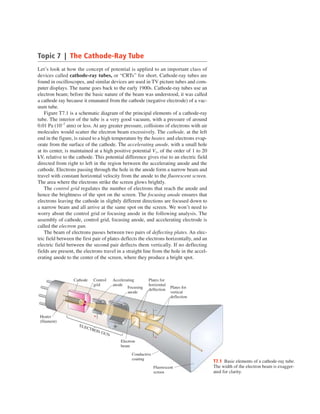
Cathode-ray tubes use an electron beam emitted from a cathode and accelerated by a positive anode to produce a spot on a fluorescent screen. The beam is deflected by electric or magnetic fields, causing the spot to move and allowing the tube to display images. The amount of deflection is directly proportional to the voltage applied. This principle is used in oscilloscopes to display signal information over time and in television and computer displays to show pictures and text.
This document discusses solar thermal power and provides an overview of solar radiation topics including:
1. The sun is an abundant source of energy that can be harnessed using solar thermal technologies.
2. It describes the solar resource and measurements of solar radiation, including quality control of data and methods to estimate radiation values.
3. It lists typical contents like the solar spectrum, relationships between the sun and earth, and databases/tools for working with solar radiation data.
This document provides an errata listing corrections to errors found in the 6th edition of the textbook "Introduction to Electric Circuits" by R.C. Dorf and J.A. Svoboda. The errata is organized by chapter and page number and provides corrections to issues such as incorrect equations, figures, answers to problems, and typos or grammatical errors in the text. A link is also provided to access the errata online which contains additional corrections not listed in the printed document.
1) Maxwell derived equations showing that changing electric fields induce magnetic fields and vice versa, allowing electromagnetic waves to propagate through space.
2) These electromagnetic waves travel at the speed of light and have oscillating electric and magnetic fields perpendicular to each other and the direction of propagation.
3) Plane electromagnetic waves satisfy the wave equation and can be described by sinusoidal functions with the electric and magnetic fields in phase but oriented at 90 degrees to each other.
In this paper a new mixed nodal-mesh formulation of the PEEC
method is proposed. Based on the hypothesis that charges reside
only on the surface of conductors and that current density is
solenoidal inside them, a novel scheme is developed fully
exploiting the physical properties of charges and currents. It
comes out that the presented approach allows to reduce the number
of unknowns while preserving the accuracy. An elegant and
efficient algorithm, based on graph theory, is proposed to
automatically search independent loops on three dimensional
rectangular grids such as those arising in volumetric PEEC
formulation. The method is validated through numerical results
that confirm the accuracy of the proposed formulation from
DC-to-daylight and its capability to provide memory saving.
This document summarizes information about magnetrons, which are microwave devices that use magnetic and electric fields to generate microwaves. Some key points:
1) Magnetrons were an early microwave device and were crucial for radar technology in World War II, allowing for the development of high-power microwave sources. Commercial magnetrons now provide powers up to several megawatts.
2) Magnetrons operate by using magnetic and electric fields to cause electrons emitted from a cathode to travel in spiral paths around an anode, interacting with resonant cavities to generate microwave oscillations.
3) The electrons form a cloud-like structure called the Brillouin cloud, confined by the magnetic field. The Hull cutoff condition relates the
Spectroscopic ellipsometry is a technique for investigating the optical properties and electrodynamics of materials. It has several advantages over other optical techniques:
1) It provides an exact numerical inversion with no need for Kramers-Kronig transformations, allowing consistency checks.
2) Measurements are non-invasive and highly reproducible as they do not require reference samples.
3) It is very sensitive to thin film properties due to its ability to measure at oblique angles of incidence.
Ellipsometry has been used to study phenomena like superconductivity in cuprates and pnictides by measuring changes in spectral weight, and collective charge ordering in oxide superlattices.
[E book] introduction to electric circuits 6th ed [r. c. dorf and j. a. svoboda]tensasparda
This document provides an errata listing corrections to errors found in the 6th edition of the textbook "Introduction to Electric Circuits" by R.C. Dorf and J.A. Svoboda. The errata is organized by chapter and page number and provides corrections to issues such as incorrect equations, figures, answers to problems, and textual errors. A link is also provided to access the errata online which contains additional corrections not listed in the printed document.
The document discusses key topics in microwave engineering including:
1. Maxwell's equations which describe the fundamentals of electromagnetics.
2. Explanations of important concepts like electric and magnetic fields, vectors, divergence, curl and boundary conditions.
3. An overview of industries utilizing RF components and analysis of the RF components market including development trends, major companies and factors changing the industry.
This document discusses electromagnetic waves and microwave engineering concepts. It covers:
1. Deriving the wave equation for electric and magnetic fields and describing wave propagation with simplified wave equations.
2. Defining key concepts like Poynting vector, electromagnetic power, wave impedance, and plane wave representations.
3. Explaining reflection, transmission, boundary conditions, and visualization of waves at interfaces between different media.
This 3 sentence summary provides the high level information about the document:
The document is an unsolved physics paper from 2007 that contains 29 multiple choice questions about various physics concepts. The questions cover topics like mechanics, electromagnetism, optics, modern physics, and thermodynamics. Each question has 4 possible answer choices, with only one being correct. The document tests conceptual understanding of fundamental physics principles through multiple choice problem solving.
1) The document provides examples of physics problems involving relativity, the photoelectric effect, and waves and particles. It includes 22 sample problems with calculations related to topics such as relativistic time dilation, relativistic length contraction, photon energy, electron kinetic energy, momentum, and de Broglie wavelength.
2) Problem 38-13 calculates the work function and kinetic energy of photoelectrons emitted from a metal surface illuminated by light of a given wavelength. It finds the work function is 1.04 eV and the kinetic energy of the emitted electrons is 2.07 eV.
3) Problem 38-21 determines the de Broglie wavelength of an electron accelerated through a potential difference. It finds the electron's momentum and calculates
1) The document summarizes key concepts from Chapter 25 of a Physics textbook about electric potential and potential energy. It includes example problems calculating work done by electric fields, potential energy, electric potential, and the relationships between charge, distance, and potential energy.
2) The chapter discusses how electric potential energy depends on the positions of charges. It can be calculated from the potential energy of a charge or the electric potential at a point in space.
3) Sample problems demonstrate calculating potential energy for various charge configurations and distances, and determining electric potential, work done by fields, and changes in potential energy when charge positions are altered.
PROBLEMAS RESUELTOS (42) DE LABORATORIO N° 1 DE FÍSICA II - TIPPENSLUIS POWELL
This document summarizes key concepts and formulas related to electric current, resistance, and Ohm's law from a physics textbook chapter. It includes:
- Formulas for calculating current, charge, resistance, voltage, power, and energy from given values.
- Examples of applying the formulas to calculate values in electric circuits.
- Concepts of resistivity and how resistance changes with temperature based on the material's temperature coefficient of resistance.
The document discusses the structure of atoms and the development of atomic models. It summarizes:
1) The subatomic particles that make up atoms - electrons, protons, and neutrons - along with their relative charges and masses.
2) Early experiments that led to the discovery of electrons and the Thomson and Rutherford atomic models.
3) Quantum numbers like atomic number and mass number that are used to describe atoms.
4) Developments in quantum theory that resulted in Bohr's model of the hydrogen atom and explanation of atomic spectra through quantized energy levels.
This summary provides the key information from the document in 3 sentences:
The document discusses nuclear physics concepts such as nuclear structure, binding energy, mass defect, radioactive decay, and half-life. It includes examples calculating physical properties like mass, radius, binding energy, and activity for various nuclei. The examples analyze nuclear reactions and decays, and solve related problems involving time, mass, energy, and radioactive decay calculations.
This chapter discusses refraction of light, including:
- The index of refraction, which is the ratio of the speed of light in a vacuum to its speed in a medium.
- Snell's law, which relates the angles of incidence and refraction based on the indices of refraction of the media.
- Total internal reflection, which occurs when light travels from an optically dense medium to a less dense one at an angle greater than the critical angle.
- Wavelength changes when light moves between media due to the index of refraction.
Several example problems are worked through applying these concepts to compute angles, indices of refraction, wavelengths and speeds of light in various materials.
This document summarizes problems from Chapter 37 on interference, diffraction, and polarization. It includes problems on Young's experiment involving constructive and destructive interference using different path lengths. Other problems cover diffraction gratings, resolving power of instruments, and the limits of angular resolution. Key concepts covered are the conditions for interference, using gratings to disperse light, and factors determining an instrument's ability to distinguish small details.
Apresentação do professor Pedro Grande, da seção UFRGS do Instituto Nacional de Engenharia de Superfície. Palestra convidada do Simpósio Engenharia de Superfície do X Encontro da SBPMAT. Realizada no dia 26 de setembro de 2011 em Gramado (RS).
- The document discusses the wave theory of light proposed by Christian Huygens in 1679, which explained properties such as interference, diffraction, and polarization that Newton's particle theory could not.
- It describes the principles of coherence and superposition of waves, which are required for the interference of light. Coherent sources exhibit a predictable correlation in amplitude and phase. The principle of superposition states that the resultant displacement of overlapping waves is the algebraic sum of the individual displacements.
- Young's double-slit experiment is discussed as providing the first evidence of light interference. When light passes through two slits, the waves spread out and interfere with each other on the screen, creating bright and dark interference fr
Problemas del Capítulo II de Física Iiiguestf39ed9c1
1) The document provides examples solving for electric field intensity and force given information about charges, distances between charges, and applied forces.
2) Gauss's law is used to show that the electric field outside a solid charged sphere is given by the equation E=Q/(4πε0r^2), where Q is the total charge on the sphere.
3) An example uses Gauss's law to solve for the electric field on the surface of a hollow metal sphere of radius 3 cm that has a +5 nC charge placed on its surface.
The Smith chart is a graphical method that is essential for microwave engineering. It allows microwave engineers to represent normalized impedances on a chart. Developed by Philip Smith in 1939, the chart maps the reflection coefficient Γ which relates the load and source impedances. It uses constant resistance and reactance circles to plot impedance points. Microwave engineers can use the Smith chart and vector network analyzers to measure reflection coefficients over frequency sweeps.
1. The document discusses various electromagnetic boundary conditions including:
- Electric and magnetic field boundary conditions between dielectric-dielectric interfaces where the normal component of B and tangential component of E are continuous.
- Conductor-dielectric boundary conditions where the surface charge density is related to the normal electric field component.
2. Faraday's law relates the rate of change of magnetic flux through a loop to the induced electromotive force around the loop. Lenz's law states that the induced current will flow such that it creates a magnetic field opposing the original change in flux.
3. The plane wave solution for electromagnetic waves in free space represents the electric and magnetic fields as propagating sinusoidal functions of space and time with
The document discusses the band structure of electrons in solids. It explains that when electrons are placed in a periodic potential, as in metals and semiconductors, the allowed energy levels split and form bands separated by band gaps. The nearly-free electron model is introduced to account for this band structure by treating electrons as interacting with a periodic lattice potential rather than being completely free. The key outcomes are that the energy-momentum relationship becomes a series of bands rather than continuous, and band gaps open up where electron states are forbidden. This distinguishes conductors, semiconductors and insulators.
The document provides details about the cathode ray oscilloscope (CRO). It discusses that the CRO is an electronic device capable of providing a visual representation of signal waveforms. It contains a cathode ray tube that uses an electron beam to produce a visible spot on a fluorescent screen. The electron beam is deflected by vertical and horizontal plates to trace electrical variations over time. The CRO contains amplifiers, a time base generator, and power supplies to operate the cathode ray tube and deflection systems. It is a versatile instrument used to observe and measure AC waveforms.
This document provides an overview of key concepts in semiconductor physics. It begins by introducing the crystal structure of silicon and how dopants can create an excess or deficiency of electrons (N-type or P-type silicon). It then discusses the energy band model and defines important terms like the band gap, Fermi energy level, density of states, and thermal equilibrium. The document derives expressions for the concentrations of electrons and holes as a function of doping, temperature, and the Fermi level position. It also examines intrinsic carrier concentration and how doping affects charge neutrality. Overall, the document establishes fundamental principles for understanding how electrons and holes behave in semiconductors.
This document discusses modeling frequency mixers as pseudo two-port devices to aid in their analysis and design. It begins with an introduction to mixers and their use in downconverters. It then presents five theories: (1) an ideal commutator model, (2) a model using Schottky diodes, (3) modeling mixers as two-port devices, (4) modeling them as linear devices, and (5) characterizing them with S-parameters. The document explores the nonlinear behavior of mixers, deriving equations to show the generation of sum and difference frequencies. It also discusses spurious products and techniques for predicting interference-free frequency ranges.
The document discusses key concepts related to optoelectronic devices and communication networks. It covers topics such as optical sources, fiber optics, optical amplifiers, add/drop devices, and optical switches. It also discusses some fundamental properties of light as an electromagnetic wave, including reflection, refraction, polarization, interference, and diffraction. Finally, it reviews key concepts regarding the behavior of light in semiconductors and optical fibers, such as refractive index, total internal reflection, and propagation of modes.
The document discusses vector fields and their representations. It defines vector fields as regions exhibiting certain properties that can be described mathematically using vector and scalar functions. The gradient, divergence and curl operators provide critical information about fields by mapping how the field varies in different coordinate systems. Any vector field can be uniquely defined and decomposed using the Helmholtz theorem based on its divergence and curl. Examples are given of different field types based on whether they are solenoidal, irrotational, or neither.
Electrochemical impedance spectroscopy is a technique used to analyze electrochemical systems by applying a small AC potential perturbation and measuring the electrical response over a range of frequencies. It allows distinguishing between different electrochemical processes and components based on their dielectric and electric properties. The technique provides quantitative data on resistances and capacitances of individual elements in a non-destructive manner and can monitor ongoing corrosion or reaction processes. Impedance data is commonly presented as Nyquist or Bode plots, with the Nyquist plot showing impedance components on the x-y axes and Bode plots using log frequency on the x-axis.
Electrochemical impedance spectroscopy is a technique used to analyze electrochemical systems. It involves applying a small AC potential perturbation and measuring the current response. The response is used to calculate impedance as a complex number. Common circuit elements like resistors and capacitors are used to model experimental data. Impedance spectroscopy provides information about individual components and processes in electrochemical systems like corrosion and batteries over time in a non-destructive way.
This document provides an overview of quantum dots. It discusses how quantum dots confine electrons in nanometer-sized volumes, behaving like artificial atoms. Transport in quantum dots exhibits Coulomb blockade, where conduction only occurs when the energy needed to add an electron to the dot is balanced by the gate potential. This leads to peaks in the conductance that are spaced by either the charging energy or level spacing of the dot. The spacing of these peaks can provide information about interactions between electrons in the quantum dot.
The document discusses optical properties of semiconductors. It begins by introducing Maxwell's equations and how they describe light propagation in a medium with both bound and free electrons. The complex refractive index is then derived, which accounts for changes to the light's velocity and damping due to absorption. Reflectivity and transmission through a thin semiconductor slab are also examined. Key equations for the complex refractive index, reflectivity, and transmission through a thin slab are provided.
The document discusses several types of semiconductor devices used for microwave generation and amplification, including MESFETs, IMPATT diodes, and TRAPATT diodes. MESFETs are metal-semiconductor field-effect transistors that operate similarly to MOSFETs but lack an insulating layer. IMPATT and TRAPATT diodes generate microwaves by exploiting carrier transit time effects during avalanche breakdown. IMPATT diodes use impact ionization in a reverse-biased p-n junction, while TRAPATT diodes trap the generated plasma carriers to achieve higher efficiencies than IMPATT diodes.
This document discusses various topics related to dielectrics and capacitors including:
- What a capacitor and dielectric material are
- How capacitance can be increased by using a dielectric
- Different polarization mechanisms in materials including electronic, ionic, orientational and interfacial polarization
- How polarization leads to the development of bound surface charges in dielectrics
- The relationship between polarization, electric susceptibility, relative permittivity and dielectric constant
- Frequency dependence of real and imaginary parts of relative permittivity due to dielectric losses
- Derivation of the Clausius-Mossotti equation relating polarization to relative permittivity
- Calculation of relative permittivity for a material considering both electronic and
Metal surfaces contain many free electrons that can escape when heated, a process known as thermionic emission. When a metal is heated, its free electrons gain enough energy to be released onto the surface. This release of electrons due to heating is what enables devices like cathode ray tubes, televisions, and computer monitors to generate beams of electrons known as cathode rays.
The document discusses various mechanisms of charge carrier transport in semiconductors including drift and diffusion. It defines carrier drift as the movement of electrons and holes under the influence of an applied electric field. Carrier mobility is introduced as a material property that determines how fast carriers drift in response to an electric field. Diffusion is defined as the movement of carriers from areas of high concentration to low concentration due to random thermal motion. The Einstein relation links diffusion and mobility through the carrier temperature. Total current in a semiconductor is the sum of drift and diffusion currents.
The Hall effect occurs when a current-carrying conductor is placed in a magnetic field. This causes charge carriers to experience a Lorentz force and build up on one side of the conductor, creating a voltage (the Hall voltage) perpendicular to both the current and the magnetic field. Measuring the Hall voltage allows determining properties of the charge carriers such as their type (electrons or holes) and density. The classical Drude model describes the Hall effect by considering electrons as particles scattering between collisions. It relates the Hall coefficient to the carrier density, providing a way to experimentally measure carrier density via the Hall effect.
Chapter3 introduction to the quantum theory of solidsK. M.
The document provides an introduction to the quantum theory of solids, including:
1. How allowed and forbidden energy bands form in solids due to the interaction of atomic electron wave functions when atoms are brought close together in a crystal lattice.
2. Electrical conduction in solids is explained using the concept of electron effective mass and holes, within the framework of the energy band model.
3. The Kronig-Penney model is used to quantitatively relate the energy, wave number, and periodic potential within a solid, resulting in allowed and forbidden energy bands.
The document discusses the theory of X-ray crystallography. X-rays have wavelengths that are suitable for probing atomic-level structure through diffraction. When X-rays hit a crystal, the scattered waves undergo constructive and destructive interference in a pattern determined by the crystal structure. Bragg's law describes the conditions under which diffraction occurs. Crystallography works by performing a Fourier transform on the electron density of the crystal to obtain structure factors, which contain information about atomic positions.
Lawrence Livermore National Laboratory
المحرك الصاروخي المعدل بقي حقيقه وقفزة علمية
بدأ اعتمادا علي المحاكاة فقط وصلا للنجاح وطبعا تحت مظلة وزاره الدفاع الامريكيه لتأمين الدعم اللازم و...
اضافة مؤثرة فعلا في تلك الصناعة
وأهم حاجه فيه ان الثرست زاد مع زياده الكفاءه ايضا ده غير ان الثرست نفسه بيعتمد علي الارتفاع
ده هيطور رحلات الذهاب >> والعوده!! كمان بشكل كبير
https://str.llnl.gov/november-2015/burton
Options for optimizing combined cycle plantsHossam Zein
This document discusses several options for optimizing the efficiency of combined cycle power plants, including:
1. Improving compressor cleanliness by using HEPA filters, which can increase power output by 6% and extend time between cleanings.
2. Making operational adjustments such as optimizing low load setpoints and reducing heat loss.
3. Installing aftermarket systems like ECOMAX automated combustion tuning to improve heat rate by 0.2-0.25% and boost output up to 11 MW.
4. A technology called TurboPHASE that uses a reciprocating engine to add compressed air to combustion turbines, allowing 10-20% faster response time and up to 7% improved heat rate.
Improve plant heat rate with feedwater heater controlHossam Zein
This document discusses improving thermal efficiency in power plants by optimizing feedwater heater performance and control. It contains the following key points:
1. Small deviations in heat rate can have large impacts on annual fuel costs, so precise control of feedwater heater levels is important for efficiency. Poor level control leads to heat losses.
2. Feedwater heaters use extraction steam to preheat feedwater and improve boiler efficiency. Accurate level control ensures optimal heat transfer. Instrument errors can degrade performance.
3. Two case studies show how unreliable level controls increased annual fuel costs by $243,000 in one plant and led to excessive heater bypasses in another. Updating controls provided paybacks of 1
A breeder reactor produces more fuel than it consumes through the conversion of uranium-238 into plutonium-239. Superphenix was a French liquid-metal fast breeder reactor that operated from 1985 to 1998. It had a thermal output of 3000 MW and an electrical output of 1174 MW. It used liquid sodium as a coolant and fuel made of MOX containing 15% uranium and 85% plutonium. Despite advantages like efficient use of uranium resources, breeder reactors also have disadvantages such as producing weapons-grade plutonium and high construction costs.
Climate change-implications-for-the-energy-sector-summary-from-ipcc-ar5-2014-...Hossam Zein
The document summarizes key findings from an IPCC report on the implications of climate change for the energy sector. It finds that climate change presents challenges for energy production and transmission as rising temperatures and extreme weather events affect infrastructure and operations. The energy sector is a major contributor to greenhouse gas emissions, and without mitigation policies emissions are projected to rise significantly by 2050 due to increasing energy demand. To keep warming below 2°C, the share of low-carbon electricity generation will need to triple or quadruple by 2050, and fossil fuel use without carbon capture will need to be phased out by 2100. Significant cuts in emissions can be achieved through measures like improving efficiency, switching fuels, expanding renewables, and carbon capture storage
امن الطاقة والبني التختيه في ضوء التخديات الخاليةHossam Zein
This document discusses critical infrastructure security in the energy sector and outlines challenges, threats, and recommendations. It defines critical infrastructure as any facility whose damage or destruction would significantly impact customers, grid reliability, national security, the economy or public health and safety. The document recommends that companies individually define and identify their critical facilities, assess security guidelines, and implement workshops to support industry. It notes recent cyberattacks like Stuxnet and outlines potential weak points and attack strategies at the facility and management levels, including available information on past terrorist attacks on international critical infrastructure related to electricity, oil/gas, water, and transportation.
Development of of power plants functionality Hossam Zein
This document discusses implementing an electrical network monitoring and control system. It examines challenges with using serial communication links for control and proposes adopting Ethernet as the physical and data link layer protocol. Specifically, it recommends replacing gateway-based architectures with a client-server model to allow multiple systems like DCS and ENMCS to independently communicate with devices like motor protection relays over high-bandwidth Ethernet. This achieves flexible communications, easy engineering access, and responses fast enough for motor control.
Planning and Zoning for Solar in North Carolina - Pandzsolar2014Hossam Zein
The document provides an overview of solar energy planning and zoning in North Carolina. It discusses the growth of the solar industry in the state and defines key solar technology terms. The summary is:
Solar energy development is growing rapidly in North Carolina, driven by falling costs and state incentives. There are two main types: solar photovoltaics (PV) convert sunlight to electricity, while solar thermal uses sunlight as heat. PV systems are composed of cells made into panels and arrays, which can be linked into large solar farms of multiple megawatts. Proper planning and zoning aims to facilitate responsible solar development while addressing potential land use impacts.
This document provides technical specifications for three photovoltaic tracking systems (sonnen_system 3_30, 3_40, 3_60) including their dimensions, weight, components, performance specifications, safety features, and monitoring capabilities. The tracking systems use an astronomical control unit and electric drives to track the sun for increased energy yield compared to fixed systems. They integrate with SMA communication and monitoring equipment to enable remote operation and performance monitoring.
The document is a user manual for the SOLTRK control unit, which controls PV tracking systems. It provides instructions for installing, connecting, commissioning and operating the SOLTRK. The SOLTRK automatically tracks the sun's position and aligns PV modules accordingly. It connects to an SMA Sunny WebBox data logger for configuration and monitoring via RS485 communication. The manual includes wiring diagrams, settings, functions and troubleshooting information to support installers and operators.
The document describes a solar tracking system called the sonnen_system that is designed to maximize solar energy collection. It precisely tracks the sun's movement throughout the day to maintain an optimal angle for solar panels, increasing energy yields by up to 45% compared to fixed systems. The sonnen_system uses a robust design and precise controls to reliably produce electricity even in extreme weather conditions, and its modular design allows for monitoring and maintenance from anywhere in the world.
SMA - SUNNY DESIGN 3 and SUNNY DESIGN WEBHossam Zein
This document is the user manual for the Sunny Design 3 and Sunny Design Web software from SMA Solar Technology AG. It provides legal information, descriptions of the product and its functions, system requirements for use, instructions for installation and use, and other guidance. The document is copyright protected and intended to help users design PV projects and systems using SMA's Sunny Design software.
Solar Power Analysis and Design Specifications Houston solarHossam Zein
This document provides a summary of technical assistance provided by SRA International to the City of Houston regarding the development of a 10 MW solar farm on a former landfill. Key points include:
- SRA conducted a site visit of the Holmes Road Landfill and determined the southern half of the site was best suited for solar development due to utility infrastructure and solar panel orientation.
- The site will require clearing and grading which may disturb the landfill cap. Contamination was also a consideration.
- Tasks performed included engineering assessments, determining the optimal solar system size and design, developing cost estimates, and conducting an economic analysis.
- The project aims to redevelop the brownfield site into a solar farm to
multi mission radar (MMR) - EL/M-2084 FOR IRON DOMEHossam Zein
multi mission radar (MMR) - EL/M-2084 FOR IRON DOME
from IAI MELTA
for more detailed info. visit -::-
http://hossamozein.blogspot.com/2011/10/iron-dome.html
1. Topic 7 | The Cathode-Ray Tube
Let’s look at how the concept of potential is applied to an important class of
devices called cathode-ray tubes, or “CRTs” for short. Cathode-ray tubes are
found in oscilloscopes, and similar devices are used in TV picture tubes and com-
puter displays. The name goes back to the early 1900s. Cathode-ray tubes use an
electron beam; before the basic nature of the beam was understood, it was called
a cathode ray because it emanated from the cathode (negative electrode) of a vac-
uum tube.
Figure T7.1 is a schematic diagram of the principal elements of a cathode-ray
tube. The interior of the tube is a very good vacuum, with a pressure of around
0.01 Pa (10−7 atm) or less. At any greater pressure, collisions of electrons with air
molecules would scatter the electron beam excessively. The cathode, at the left
end in the figure, is raised to a high temperature by the heater, and electrons evap-
orate from the surface of the cathode. The accelerating anode, with a small hole
at its center, is maintained at a high positive potential V1, of the order of 1 to 20
kV, relative to the cathode. This potential difference gives rise to an electric field
directed from right to left in the region between the accelerating anode and the
cathode. Electrons passing through the hole in the anode form a narrow beam and
travel with constant horizontal velocity from the anode to the fluorescent screen.
The area where the electrons strike the screen glows brightly.
The control grid regulates the number of electrons that reach the anode and
hence the brightness of the spot on the screen. The focusing anode ensures that
electrons leaving the cathode in slightly different directions are focused down to
a narrow beam and all arrive at the same spot on the screen. We won’t need to
worry about the control grid or focusing anode in the following analysis. The
assembly of cathode, control grid, focusing anode, and accelerating electrode is
called the electron gun.
The beam of electrons passes between two pairs of deflecting plates. An elec-
tric field between the first pair of plates deflects the electrons horizontally, and an
electric field between the second pair deflects them vertically. If no deflecting
fields are present, the electrons travel in a straight line from the hole in the accel-
erating anode to the center of the screen, where they produce a bright spot.
Cathode Control Accelerating Plates for
grid anode horizontal
Focusing Plates for
deflection
anode vertical
deflection
–
Heater +
(filament)
ELE
CTR
ON
GUN
+
Electron
beam
Conductive
coating
T7.1 Basic elements of a cathode-ray tube.
Fluorescent The width of the electron beam is exagger-
screen ated for clarity.
2. To analyze the electron motion, let’s first calculate the speed v of the electrons
as they leave the electron gun. The initial speeds at which the electrons are emit-
ted from the cathode are very small in comparison to their final speeds, so we
assume that the initial speeds are zero. Then the speed vx of the electrons as they
leave the electron gun is given by
2eV1 (T7.1)
vx 5
Å m
The kinetic energy of an electron leaving the anode depends only on the potential
difference between anode and cathode, not on the details of the fields or the elec-
tron trajectories within the electron gun. As a numerical example, if V1 = 2000 V,
2 1 1.60 3 10219 C 2 1 2.00 3 103 V 2
vx 5 5 2.65 3 107 m/s
Å 9.11 3 10231 kg
This is about 9% of the speed of light in a vacuum.
If there is no electric field between the horizontal-deflection plates, the elec-
trons enter the region between the vertical-deflection plates (shown in Fig. T7.2)
with speed vx. If there is a potential difference (voltage) V2 between these plates,
with the upper plate at higher potential, there is a downward electric field with
magnitude E = V2/d between the plates. A constant upward force with magnitude
eE then acts on the electrons, and their upward (y-component) acceleration is
eE eV2
ay 5 5 (T7.2)
m md
The horizontal component of velocity vx is constant. The path of the electrons in
the region between the plates is a parabolic trajectory. A particle moves with
constant x-velocity and constant y-acceleration. After the electrons emerge from
this region, their paths again become straight lines, and they strike the screen at
a point a distance y above its center. We are going to prove that this distance is
directly proportional to the deflecting potential difference V2.
We first note that the time t required for the electrons to travel the length L of
the plates is
L
t5 (T7.3)
vx
During this time, they acquire an upward velocity component vy given by
vy 5 ayt (T7.4)
Combining Eqs. (T7.2), (T7.3), and (T7.4), we find
eV2 L
vy 5 (T7.5)
md vx
When the electrons emerge from the deflecting field, their velocity µ makes an
angle u with the x-axis given by
vy
tan u 5 (T7.6)
vx
3. y Screen
–
vy v
+ + + + y
r vx
E u
d – x
O vx
– – – –
T7.2 Electrostatic deflection of an electron
L D beam in a cathode-ray tube.
Ordinarily, the length L of the deflection plates is much smaller than the distance
D from the plates to the screen. In this case the angle u is also given approximately
by tan u = y/D. Combining this with Eq. (T7.6), we find
y vy (T7.7)
5
D vx
or, using Eq. (T7.5) to eliminate vy, we get
DeV2L
y5 (T7.8)
mdvx 2
Finally, we substitute the expression for vx given by Eq. (T7.1) into Eq. (T7.8); the
result is
y5
LD V2
2d V1 1 2 (T7.9)
The factor in parentheses depends only on the dimensions of the system, which
are all constants. So we have proved that the deflection y is proportional to the
deflecting voltage V2, as claimed. It is also inversely proportional to the acceler-
ating voltage V1. This isn’t surprising; the faster the electrons are going, the less
they are deflected by the deflecting voltage.
If there is also a field between the horizontal deflecting plates, the beam is also
deflected in the horizontal direction, perpendicular to the plane of Fig. T7.2. The
coordinates of the luminous spot on the screen are then proportional to the hori-
zontal and vertical deflecting voltages, respectively. This is the principle of the
cathode-ray oscilloscope. If the horizontal deflection voltage sweeps the beam
from left to right at a uniform rate, the beam traces out a graph of the vertical volt-
age as a function of time. Oscilloscopes are extremely useful laboratory instru-
ments in many areas of pure and applied science.
The picture tube in a television set is similar, but the beam is deflected by mag-
netic fields rather than electric fields. In the system currently used in the United
States and Canada, the electron beam traces out the area of the picture 30 times
per second in an array of 525 horizontal lines, and the intensity of the beam is var-
ied to make bright and dark areas on the screen. (In a color set, the screen is an
array of dots of phosphors with three different colors.) The accelerating voltage in
TV picture tubes (V1 in the above discussion) is typically about 20 kV. Computer
displays and monitors operate on the same principle, using a magnetically
deflected electron beam to trace out images on a fluorescent screen. In this con-
text the device is called a CRT display or a VDT (video display terminal). (Flat
screen monitors and TVs use an entirely different technology.)