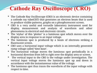
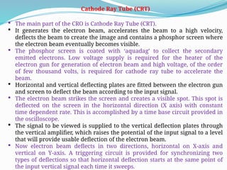
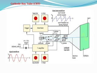
Cathode Ray Oscilloscope(CRO)
The Cathode Ray Oscilloscope (CRO) is an electronic device containing
a cathode ray tube(CRT) that generates an electron beam that is used
to produce visible patterns, graphs on a phosphorescent screen.
CRO is a very useful and versatile laboratory instrument used for
display, measurement and analysis of waveform and other
phenomena in electrical and electronic circuits.
The ‘stylus’ of this ‘plotter’ is a luminous spot which moves over the
display area in response to an input voltage.
The luminous spot is produced by a beam of electrons striking a
fluorescent screen.
CRO uses a horizontal input voltage which is an internally generated
ramp voltage called ‘time base’.
The horizontal voltage moves the luminous spot periodically in a
horizontal direction from left to right over the display area or screen.
The vertical input to the CRO is the voltage under investigation. The
vertical input voltage moves the luminous spot up and down in
accordance with the instantaneous value of the voltage.
The luminous spot thus traces the waveform of the input voltage with
respect to time.
3.
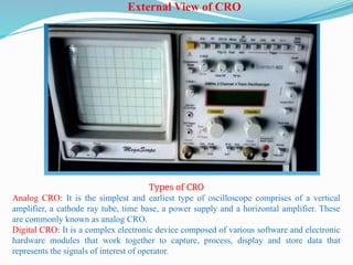
External View ofCRO
Types of CRO
Analog CRO: It is the simplest and earliest type of oscilloscope comprises of a vertical
amplifier, a cathode ray tube, time base, a power supply and a horizontal amplifier. These
are commonly known as analog CRO.
Digital CRO: It is a complex electronic device composed of various software and electronic
hardware modules that work together to capture, process, display and store data that
represents the signals of interest of operator.
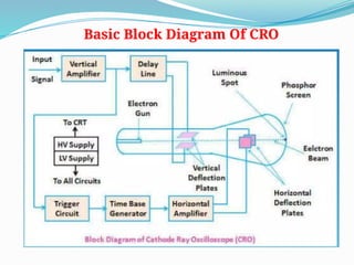
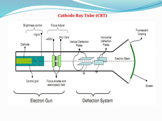
Cathode Ray Tube(CRT)
The main part of the CRO is Cathode Ray Tube (CRT).
It generates the electron beam, accelerates the beam to a high velocity,
deflects the beam to create the image and contains a phosphor screen where
the electron beam eventually becomes visible.
The phosphor screen is coated with ‘aquadag’ to collect the secondary
emitted electrons. Low voltage supply is required for the heater of the
electron gun for generation of electron beam and high voltage, of the order
of few thousand volts, is required for cathode ray tube to accelerate the
beam.
Horizontal and vertical deflecting plates are fitted between the electron gun
and screen to deflect the beam according to the input signal.
The electron beam strikes the screen and creates a visible spot. This spot is
deflected on the screen in the horizontal direction (X axis) with constant
time dependent rate. This is accomplished by a time base circuit provided in
the oscilloscope.
The signal to be viewed is supplied to the vertical deflection plates through
the vertical amplifier, which raises the potential of the input signal to a level
that will provide usable deflection of the electron beam.
Now electron beam deflects in two directions, horizontal on X-axis and
vertical on Y-axis. A triggering circuit is provided for synchronizing two
types of deflections so that horizontal deflection starts at the same point of
the input vertical signal each time it sweeps.
7.
The CRT iscomposed of two main parts:
Electron Gun:
Deflection System :
Electron gun:
It provides a sharply focused electron beam directed toward the
fluorescent-coated screen.
The thermally heated cathode emits electrons in many directions. The
control grid provides an axial direction for the electron beam and controls
the number and speed of electrons in the beam.
The momentum of the electrons determines the intensity, or brightness, of
the light emitted from the fluorescent coating due to the electron
bombardment. Because electrons are negatively charged, a repulsion
force is created by applying a negative voltage to the control grid, to adjust
their number and speed.
A more negative voltage results in less number of electrons in the beam
and hence decreased brightness of the beam spot. Since the electron beam
consists of many electrons, the beam tends to diverge. This is because the
similar (negative) charges on the electrons repulse each other. To
compensate for such repulsion forces, an adjustable electrostatic field is
created between two cylindrical anodes, called the focusing anodes. The
variable positive voltage on the second anode cylinder is therefore used to
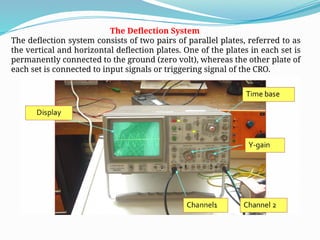
The Deflection System
Thedeflection system consists of two pairs of parallel plates, referred to as
the vertical and horizontal deflection plates. One of the plates in each set is
permanently connected to the ground (zero volt), whereas the other plate of
each set is connected to input signals or triggering signal of the CRO.
10.
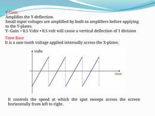
Y-Gain
Amplifies the Y-deflection.
Smallinput voltages are amplified by built-in amplifiers before applying
to the Y-plates.
Y- Gain = 0.5 V/div • 0.5 volt will cause a vertical deflection of 1 division
Time Base
It is a saw-tooth voltage applied internally across the X-plates.
It controls the speed at which the spot sweeps across the screen
horizontally from left to right.
11.
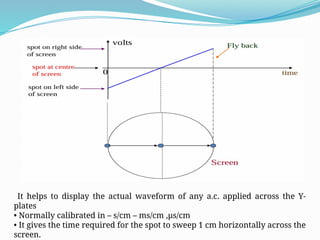
It helps todisplay the actual waveform of any a.c. applied across the Y-
plates
• Normally calibrated in – s/cm – ms/cm ,µs/cm
• It gives the time required for the spot to sweep 1 cm horizontally across the
screen.
12.
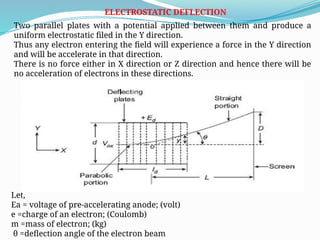
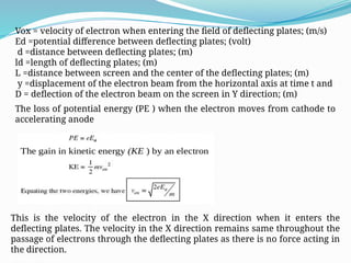
ELECTROSTATIC DEFLECTION
Two parallelplates with a potential applied between them and produce a
uniform electrostatic filed in the Y direction.
Thus any electron entering the field will experience a force in the Y direction
and will be accelerate in that direction.
There is no force either in X direction or Z direction and hence there will be
no acceleration of electrons in these directions.
Let,
Ea = voltage of pre-accelerating anode; (volt)
e =charge of an electron; (Coulomb)
m =mass of electron; (kg)
θ =deflection angle of the electron beam
13.
Vox = velocityof electron when entering the field of deflecting plates; (m/s)
Ed =potential difference between deflecting plates; (volt)
d =distance between deflecting plates; (m)
ld =length of deflecting plates; (m)
L =distance between screen and the center of the deflecting plates; (m)
y =displacement of the electron beam from the horizontal axis at time t and
D = deflection of the electron beam on the screen in Y direction; (m)
The loss of potential energy (PE ) when the electron moves from cathode to
accelerating anode
This is the velocity of the electron in the X direction when it enters the
deflecting plates. The velocity in the X direction remains same throughout the
passage of electrons through the deflecting plates as there is no force acting in
the direction.
14.
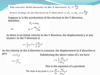
Suppose ay isthe acceleration of the electron in the Y direction,
therefore
As there is no initial velocity in the Y direction, the displacement y at any
instant t in the Y direction is
As the velocity in the X direction is constant, the displacement in X direction is
given by Substituting the above value of t, we have
This is the equation of a parabola
15.
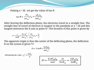
Putting x =ld , we get the value of tan θ.
After leaving the deflection plates, the electrons travel in a straight line. The
straight line of travel of electron is tangent to the parabola at x = ld and this
tangent intersects the X axis at point O’. The location of this point is given by
The apparent origin is thus the center of the deflecting plates, the deflection
D on the screen is given by
16.
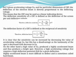
For a givenaccelerating voltage Ea, and for particular dimensions of CRT, the
deflection of the electron beam is directly proportional to the deflecting
voltage.
This means that the CRT may be used as a linear indicating device.
The deflection sensitivity of a CRT is defined as the deflection of the screen
per unit deflection voltage.
The deflection factor of a CRT is defined as the reciprocal of sensitivity
It is clear that the sensitivity can be increased by decreasing the value of
accelerating voltage Ea. but this has a disadvantage as the luminosity of the
spot is decreased with decrease in Ea.
On the other hand a high value of Ea, produced a highly accelerated beam
and thus produces a bright spot. However, a high accelerating voltage (Ea)
requires a high deflection potential (Ed) for a given deflection.
Highly accelerated beam is more difficult to deflect and is sometimes called
hard beam.
17.
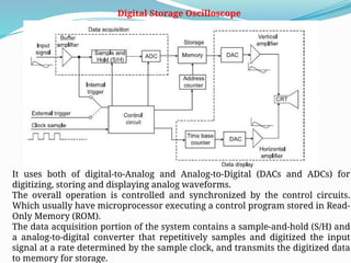
Digital Storage Oscilloscope
Ituses both of digital-to-Analog and Analog-to-Digital (DACs and ADCs) for
digitizing, storing and displaying analog waveforms.
The overall operation is controlled and synchronized by the control circuits.
Which usually have microprocessor executing a control program stored in Read-
Only Memory (ROM).
The data acquisition portion of the system contains a sample-and-hold (S/H) and
a analog-to-digital converter that repetitively samples and digitized the input
signal at a rate determined by the sample clock, and transmits the digitized data
to memory for storage.
18.
The control circuitmakes sure that successive data points are stored in
successive memory locations by continually updating the memory’s address
counter.
Data acquisition and the storage process continue until the control circuit
receives a trigger signal from either the input waveform (internal trigger) or
an external trigger source.
When the triggering occurs, the system stops acquiring data further and
enters the display mode of operation, in which all or part of the memory data
is repetitively displayed on the Cathode Ray Tube (CRT).
In display operation two DACs are employed for providing the vertical and
horizontal deflecting voltages for the cathode ray tube.
Data from memory produce the vertical deflection of the electron beam,
while the time base counter provides the horizontal deflection in the form of
a staircase sweep signal.
The control circuits synchronize the display operation by incrementing the
memory address counter and the time base counter at the same time so that
each horizontal step of the electron beam is accompanied by a new data
value from the memory to the vertical DAC.
The counters are continuously recycled so that the stored data points are
repetitively re-plotted on the screen of the CRT.