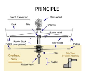
TELEMOTOR
STRG GEAR
• Three types
• Fully hydraulic type
• Electro-hydraulic type
• Fully electric type
• Electro-hydraulic type gear arrangement is
most common.
COMPONENTS
• Complete Steering Gear system consists of
three main parts namely
• Telemotor
• Control Unit
• Power Unit.
• Transmission to rudder
WORKING
• The steering gear provides a movement of the
rudder in response to signal from the bridge.
• The control equipment conveys a signal of
desired rudder angle from the bridge and
activates the power unit and transmission
system until the desired angle is reached.
WORKING
• The power unit provides the force, when
required and with immediate effect, to move
the rudder to the desired angle.
• The transmission system & the steering gear,
is the means by which the movement of the
rudder is accomplished.
Telemotor control
• Telemotor control is a hydraulic control system
employing a transmitter, a receiver, pipes and a
charging unit.
• The transmitter is built into the steering wheel
console on the bridge.
• The receiver is mounted on the steering gear.
• The charging unit is located near to the receiver
and the system is charged with a non-freezing
fluid.
CONTROL/PWR UNITS
• Control Unit is the link between the Telemotor and the
Power Unit.
• It receives signal from the Telemotor and operates the
Power Unit until it receives another signal, this time
from the Rudder through the Hunting Gear, to stop the
operation of Power Unit.
• Power Unit can be any prime mover like an electric
motor directly coupled to the Rudder;
• Or a electro-hydraulic unit
• or an all- electric unit complete with the Tele motor.
RAMS
• Two rams are present in the transmitter which
move in opposite directions as the steering wheel
is turned.
• The fluid is therefore pumped down one pipe
line and drawn in from the other. The pumped
fluid passes through piping to the receiver and
forces the telemotor cylinder unit to move.
• The suction of fluid from the opposite cylinder
enables this movement to take place.
VARIABLE DISP PP
• The displacement, or amount of fluid pumped
per revolution of the pump's input shaft can
be varied while the pump is running.
• The cylinder unit has a control spindle connected to it by a
pin.
• If the changeover pin is removed from the cylinder unit
and inserted in the local hand wheel drive then manual
control of the steering gear is possible.
• Stops are fitted on the receiver to limit movement to the
maximum rudder angle required.
• The charging unit consists of a tank, a pump, and shut-off
cocks for each and is fitted in the main piping between the
transmitter and receiver.
• In the transmitter a replenishing tank surrounds the rams,
ensuring that air cannot enter the system.
• A bypass between the two cylinders opens as the
wheel passes midships.
• Also at mid position the supercharging unit provides a
pressure in the system which ensures rapid response of
the system to a movement of the wheel.
• This supercharging unit draws in replenishing fluid if
required in the system, and provides a relief valve
arrangement if the pressure is too high.
• Pressure gauges are connected to each main pipeline
and air vent cocks are also provided.
• In normal operation the working pressure of about 20
to 30 bar.
• The wheel should not be forced beyond the 'hard over'
position as this will strain the gear.
The replenishing tank should be checked regularly and
any lubrication points should receive attention.
• Any leaking or damaged equipment must be repaired
or replaced as soon as possible.
• The system should be regularly checked for pressure
tightness.
• The rudder response to wheel movement
should be checked and if sluggish or slow then
air venting undertaken.
• If, after long service, air venting does not
remove sluggishness, it may be necessary to
recharge the system with new fluid.
• As per standard requirements, the steering gear
should be capable of steering the ship from 35
degrees port to 35 degrees starboard and vice-
versa with the vessel moving ahead at a steady
head-on speed for maximum continuous rated
shaft rpm and summer load waterline within a
time frame of maximum 28 seconds
•
• Emergency Power Supply: The steering gear
system is to be provided with additional
power unit (hydraulic pump etc.) connected to
the emergency power supply from Emergency
Generator.
• Deficiency of fluid made up automatically
from replenishing tanks facilitated by a by pass
valve in the transmitting unit.
PRINCIPLE
FOLLOWUP
• Hunting gear used.
• Activates the hyd pp for moving rams so that
rudder reaches the right posn.
• It is a feed back mechanism of steering gear
which repositions the floating lever of
hydraulic pump as the tiller moves to the
desired position.
NON FOLLOWUP
AIR IN STRG SYS
• INDICATIONS
• Jumping pressure gauges
• Jerky operation
• Defective steering
EMRG STRG
• In the case of Telemotor failure, by switching the
change over pin, emergency steering can be
carried out by isolating the receiver cylinder and
directly controlling the connecting rod of the
main steering power unit’s pump lever.
• The rudder angle indicator and communication
system to bridge is provided at the emergency
station.
Control test
• 1 hour before departure of vessel.
•
Control test
• 12 hour before departure
• Operation of main & auxiliary steering gear.
• Operation of remote control system.
• Operation of emergency power supply.
• Alarm test.
• Actual rudder angle & indicator.
• Communication system.(Bridge, Engine room &
Steering gear room)
•
Every 3 months interval
• Emergency steering gear drill at steering flat /
bridge with sound communication system.
•
TELEMOTOR steering gear and its components

TELEMOTOR steering gear and its components

  • 1.
  • 2.
    STRG GEAR • Threetypes • Fully hydraulic type • Electro-hydraulic type • Fully electric type • Electro-hydraulic type gear arrangement is most common.
  • 3.
    COMPONENTS • Complete SteeringGear system consists of three main parts namely • Telemotor • Control Unit • Power Unit. • Transmission to rudder
  • 4.
    WORKING • The steeringgear provides a movement of the rudder in response to signal from the bridge. • The control equipment conveys a signal of desired rudder angle from the bridge and activates the power unit and transmission system until the desired angle is reached.
  • 5.
    WORKING • The powerunit provides the force, when required and with immediate effect, to move the rudder to the desired angle. • The transmission system & the steering gear, is the means by which the movement of the rudder is accomplished.
  • 6.
    Telemotor control • Telemotorcontrol is a hydraulic control system employing a transmitter, a receiver, pipes and a charging unit. • The transmitter is built into the steering wheel console on the bridge. • The receiver is mounted on the steering gear. • The charging unit is located near to the receiver and the system is charged with a non-freezing fluid.
  • 7.
    CONTROL/PWR UNITS • ControlUnit is the link between the Telemotor and the Power Unit. • It receives signal from the Telemotor and operates the Power Unit until it receives another signal, this time from the Rudder through the Hunting Gear, to stop the operation of Power Unit. • Power Unit can be any prime mover like an electric motor directly coupled to the Rudder; • Or a electro-hydraulic unit • or an all- electric unit complete with the Tele motor.
  • 8.
    RAMS • Two ramsare present in the transmitter which move in opposite directions as the steering wheel is turned. • The fluid is therefore pumped down one pipe line and drawn in from the other. The pumped fluid passes through piping to the receiver and forces the telemotor cylinder unit to move. • The suction of fluid from the opposite cylinder enables this movement to take place.
  • 9.
    VARIABLE DISP PP •The displacement, or amount of fluid pumped per revolution of the pump's input shaft can be varied while the pump is running.
  • 10.
    • The cylinderunit has a control spindle connected to it by a pin. • If the changeover pin is removed from the cylinder unit and inserted in the local hand wheel drive then manual control of the steering gear is possible. • Stops are fitted on the receiver to limit movement to the maximum rudder angle required. • The charging unit consists of a tank, a pump, and shut-off cocks for each and is fitted in the main piping between the transmitter and receiver. • In the transmitter a replenishing tank surrounds the rams, ensuring that air cannot enter the system.
  • 11.
    • A bypassbetween the two cylinders opens as the wheel passes midships. • Also at mid position the supercharging unit provides a pressure in the system which ensures rapid response of the system to a movement of the wheel. • This supercharging unit draws in replenishing fluid if required in the system, and provides a relief valve arrangement if the pressure is too high. • Pressure gauges are connected to each main pipeline and air vent cocks are also provided.
  • 12.
    • In normaloperation the working pressure of about 20 to 30 bar. • The wheel should not be forced beyond the 'hard over' position as this will strain the gear. The replenishing tank should be checked regularly and any lubrication points should receive attention. • Any leaking or damaged equipment must be repaired or replaced as soon as possible. • The system should be regularly checked for pressure tightness.
  • 13.
    • The rudderresponse to wheel movement should be checked and if sluggish or slow then air venting undertaken. • If, after long service, air venting does not remove sluggishness, it may be necessary to recharge the system with new fluid.
  • 14.
    • As perstandard requirements, the steering gear should be capable of steering the ship from 35 degrees port to 35 degrees starboard and vice- versa with the vessel moving ahead at a steady head-on speed for maximum continuous rated shaft rpm and summer load waterline within a time frame of maximum 28 seconds •
  • 15.
    • Emergency PowerSupply: The steering gear system is to be provided with additional power unit (hydraulic pump etc.) connected to the emergency power supply from Emergency Generator.
  • 16.
    • Deficiency offluid made up automatically from replenishing tanks facilitated by a by pass valve in the transmitting unit.
  • 17.
  • 18.
    FOLLOWUP • Hunting gearused. • Activates the hyd pp for moving rams so that rudder reaches the right posn. • It is a feed back mechanism of steering gear which repositions the floating lever of hydraulic pump as the tiller moves to the desired position.
  • 19.
  • 20.
    AIR IN STRGSYS • INDICATIONS • Jumping pressure gauges • Jerky operation • Defective steering
  • 21.
    EMRG STRG • Inthe case of Telemotor failure, by switching the change over pin, emergency steering can be carried out by isolating the receiver cylinder and directly controlling the connecting rod of the main steering power unit’s pump lever. • The rudder angle indicator and communication system to bridge is provided at the emergency station.
  • 22.
    Control test • 1hour before departure of vessel. •
  • 23.
    Control test • 12hour before departure • Operation of main & auxiliary steering gear. • Operation of remote control system. • Operation of emergency power supply. • Alarm test. • Actual rudder angle & indicator. • Communication system.(Bridge, Engine room & Steering gear room) •
  • 24.
    Every 3 monthsinterval • Emergency steering gear drill at steering flat / bridge with sound communication system. •