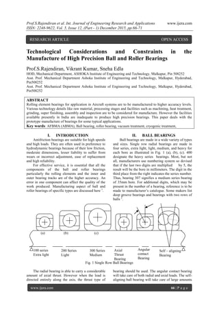
Manufacture of High Precision Ball and Roller Bearings
•
0 likes•116 views

Rolling element bearings for application in Aircraft systems are to be manufactured to higher accuracy levels. Various technology details like raw material, processing stages and facilities such as machining, heat treatment, grinding, super finishing, assembly and inspection are to be considered for manufacture. However the facilities available presently in India are inadequate to produce high precision bearings. This paper deals with the prototype manufacture of bearings for some typical applications.
![Prof.S.Rajendiran et al. Int. Journal of Engineering Research and Applications www.ijera.com
ISSN: 2248-9622, Vol. 5, Issue 12, (Part - 1) December 2015, pp.66-71
www.ijera.com 67 | P a g e
of angular misalignment. An increase in radial
capacity may be secured by using rings with deep
grooves, or by employing a double row radial
bearing.
Radial bearings are divided into two general
classes, depending on the method of assembly (Fig.
2). These are the Conrad, or nonfilling-notch type,
and the maximum, or filling-notch type. In Conrad
bearing, the balls are placed between the rings as
shown in Fig 2.(a). Then they are evenly spaced and
the separator is riveted in place. In the maximum
type bearing, the balls are inserted through a filling
notch ground into each ring, as shown in Fig.2.(b).
Because more balls can be placed in such bearings,
their load capacity is greater than that of the Conrad
type. However the presence of the notches limits the
load-carrying capacity of these bearings in the axial
direction.
(a) (b)
Fig 2. Ball Bearings Assembly3
Fig. 3. Types of Roller Bearings3
III. CYLINDRICAL ROLLER
BEARING
The cylindrical roller bearings have greater
radial load capacity than ball bearings of same
external dimensions and are particularly suitable for
arduous duties. The bearings feature a modified
line contact between rollers and raceways to
eliminate edge stressing 3
. The direction of axial
load, which a bearing can take, depends upon the
geometry of the bearing. Many variations available
are shown in Fig. 3.
IV. PRECISION LEVELS OF
BEARINGS
A wide variety of rolling-contact bearings are
normally manufactured to standard boundary
dimensions (Bore, outside diameter, width) and
tolerances, which have been standardized by
AFBMA. All bearing manufacturers conform to
these standards, thereby permitting
interchangeability. ANSI has adopted these and
published them jointly as AFBMA / ANSI standards
as shown in table.1.
Table 1. AFBMA Standards 4
Title Standard Title Standard
Terminology
Gauging
practice
Mounting
Dimensions
Mounting
Accessories
Ball load
Ratings
1
4
7
8.2
9
Ball
standards
Roller load
Ratings
Instrument
bearings
Vibration
and Noise
Basic
boundary
Dimensions
10
11
12
13
20
The Annular Bearings Engineers Committee
(ABEC) of AFBMA has established progressive
levels of precision for all ball bearings, designated as
ABEC – 1, ABEC – 3, ABEC – 5, ABEC – 7, and
ABEC – 9. These standards specify tolerances for
bore, outside diameter, width, and radial runout.
Similarly, Roller Bearings Engineers Committee
have established precision levels as RBEC – 1,
RBEC – 5 etc,.
The comparative classes of precision levels in
different standards are given in Table 2.
Table 2. Comparison of standards
ABMA (AFBMA) ABEC 1 ABEC 3 ABEC 5 ABEC 7 ABEC 9
JIS / ISO CLASS 0 CLASS 6 CLASS 5 CLASS 4 CLASS 2
DIN P 0 P 6 P 5 P 4 P 2
[Source: promowebnet.qc.ca]](data:image/gif;base64,R0lGODlhAQABAIAAAAAAAP///yH5BAEAAAAALAAAAAABAAEAAAIBRAA7)
Recommended
More Related Content
What's hot
What's hot (20)
Viewers also liked
Viewers also liked (20)
Similar to Manufacture of High Precision Ball and Roller Bearings
Similar to Manufacture of High Precision Ball and Roller Bearings (20)
Recently uploaded
Recently uploaded (20)
Manufacture of High Precision Ball and Roller Bearings
- 1. Prof.S.Rajendiran et al. Int. Journal of Engineering Research and Applications www.ijera.com ISSN: 2248-9622, Vol. 5, Issue 12, (Part - 1) December 2015, pp.66-71 www.ijera.com 66 | P a g e 100 series Extra light 200 Series Light 300 Series Medium Axial Thrust Bearing Angular contact Bearing Self – aligning Bearing Technological Considerations and Constraints in the Manufacture of High Precision Ball and Roller Bearings Prof.S.Rajendiran, Vikrant Kumar, Sneha Edla HOD, Mechanical Department, ASHOKA Institute of Engineering and Technology, Malkapur, Pin 508252 Asst. Prof. Mechanical Department Ashoka Institute of Engineering and Technology, Malkapur, Hyderabad, Pin508252 Asst. Prof. Mechanical Department Ashoka Institute of Engineering and Technology, Malkapur, Hyderabad, Pin508252 ABSTRACT Rolling element bearings for application in Aircraft systems are to be manufactured to higher accuracy levels. Various technology details like raw material, processing stages and facilities such as machining, heat treatment, grinding, super finishing, assembly and inspection are to be considered for manufacture. However the facilities available presently in India are inadequate to produce high precision bearings. This paper deals with the prototype manufacture of bearings for some typical applications. Key words: AFBMA (ABMA), Ball bearing, roller bearing, vacuum treatment, cryogenic treatment, I. INTRODUCTION Antifriction bearings are suitable for high speeds and high loads. They are often used in preference to hydrodynamic bearings because of their low friction, moderate dimensions, lesser liability to suffer from wears or incorrect adjustment, ease of replacement and high reliability. For effective service, it is essential that all the components of the ball and roller bearings particularly the rolling elements and the inner and outer bearing tracks are of the higher accuracy. An error in one component can affect the quality of the work produced. Manufacturing aspect of ball and roller bearings of specific types are discussed here 1 . II. BALL BEARINGS Ball bearings are made in a wide variety of types and sizes. Single row radial bearings are made in four series, extra light, light, medium, and heavy for each bore as illustrated in Fig. 1 (a), (b), (c). 400 designate the heavy series bearings. Most, but not all, manufacturers use numbering system so devised that if the last two digits are multiplied by 5, the result will be the bore in millimeters. The digit in the third place from the right indicates the series number. Thus, bearing 307 signifies a medium series bearing of 35mm bore. For additional digits, which may be present in the number of a bearing, reference is to be made to manufacturer’s catalogue. Some makers list deep groove bearings and bearings with two rows of balls 2 . (a) (b) (c) Fig. 1 Single Row Ball Bearings The radial bearing is able to carry a considerable amount of axial thrust. However when the load is directed entirely along the axis, the thrust type of bearing should be used. The angular contact bearing will take care of both radial and axial loads. The self- aligning ball bearing will take care of large amounts RESEARCH ARTICLE OPEN ACCESS
- 2. Prof.S.Rajendiran et al. Int. Journal of Engineering Research and Applications www.ijera.com ISSN: 2248-9622, Vol. 5, Issue 12, (Part - 1) December 2015, pp.66-71 www.ijera.com 67 | P a g e of angular misalignment. An increase in radial capacity may be secured by using rings with deep grooves, or by employing a double row radial bearing. Radial bearings are divided into two general classes, depending on the method of assembly (Fig. 2). These are the Conrad, or nonfilling-notch type, and the maximum, or filling-notch type. In Conrad bearing, the balls are placed between the rings as shown in Fig 2.(a). Then they are evenly spaced and the separator is riveted in place. In the maximum type bearing, the balls are inserted through a filling notch ground into each ring, as shown in Fig.2.(b). Because more balls can be placed in such bearings, their load capacity is greater than that of the Conrad type. However the presence of the notches limits the load-carrying capacity of these bearings in the axial direction. (a) (b) Fig 2. Ball Bearings Assembly3 Fig. 3. Types of Roller Bearings3 III. CYLINDRICAL ROLLER BEARING The cylindrical roller bearings have greater radial load capacity than ball bearings of same external dimensions and are particularly suitable for arduous duties. The bearings feature a modified line contact between rollers and raceways to eliminate edge stressing 3 . The direction of axial load, which a bearing can take, depends upon the geometry of the bearing. Many variations available are shown in Fig. 3. IV. PRECISION LEVELS OF BEARINGS A wide variety of rolling-contact bearings are normally manufactured to standard boundary dimensions (Bore, outside diameter, width) and tolerances, which have been standardized by AFBMA. All bearing manufacturers conform to these standards, thereby permitting interchangeability. ANSI has adopted these and published them jointly as AFBMA / ANSI standards as shown in table.1. Table 1. AFBMA Standards 4 Title Standard Title Standard Terminology Gauging practice Mounting Dimensions Mounting Accessories Ball load Ratings 1 4 7 8.2 9 Ball standards Roller load Ratings Instrument bearings Vibration and Noise Basic boundary Dimensions 10 11 12 13 20 The Annular Bearings Engineers Committee (ABEC) of AFBMA has established progressive levels of precision for all ball bearings, designated as ABEC – 1, ABEC – 3, ABEC – 5, ABEC – 7, and ABEC – 9. These standards specify tolerances for bore, outside diameter, width, and radial runout. Similarly, Roller Bearings Engineers Committee have established precision levels as RBEC – 1, RBEC – 5 etc,. The comparative classes of precision levels in different standards are given in Table 2. Table 2. Comparison of standards ABMA (AFBMA) ABEC 1 ABEC 3 ABEC 5 ABEC 7 ABEC 9 JIS / ISO CLASS 0 CLASS 6 CLASS 5 CLASS 4 CLASS 2 DIN P 0 P 6 P 5 P 4 P 2 [Source: promowebnet.qc.ca]
- 3. Prof.S.Rajendiran et al. Int. Journal of Engineering Research and Applications www.ijera.com ISSN: 2248-9622, Vol. 5, Issue 12, (Part - 1) December 2015, pp.66-71 www.ijera.com 68 | P a g e V. MANUFACTURING ASPECTS 5.1 Parts of Bearings A Bearing consists of Outer race, Inner race, Rolling elements (Balls or rollers) Cages and /or rivets 5.2 Materials for bearing elements For ideal operating conditions, the requirements are (i) low cost, (ii) adequate strength and rigidity, (iii) good thermal conductivity, and (iv) ease of being machined. However, there are some deviations such as (i) starting and stopping, low speed, (ii) too high load at too low speed – thereby having partial support by direct contact between surfaces, (iii) shaft deflection under load – rubbing at the ends, (iv) inadequate lubricant supply, (v) fluctuating loads as for example in connecting rod, main bearings in I.C Engines and compressors etc., (vi) contaminated lubricant, and (vii) lack of surface smoothness. All these place additional requirements on bearing materials. These requirements can be listed as 4 : 1. Score resistance (Compatibility) 2. Conformability 3. Embedability 4. Compressive strength 5. Fatigue strength 6. Corrosion resistance 7. Modulus of Elasticity 8. Thermal conductivity 9. Cost and availability Various materials used for various rolling elements of bearing are M50, SAE 52100 / 100 Cr 6, 80DCV 40DFV (AMS 6491) etc., The cages are made out of bronze tube and rivets are made out of steel wire to AMS 5689. Bearings steels, depending on the reliability, must be in a condition with less impurity level to improve fatigue resistance. The material should undergo one of the various refining processes viz. Vacuum degassing (VD), Electro slag remelting (ESR), a consumable electrode vacuum remelt (CEVM) or double vacuum remelt. 5.3 TECHNICAL REQUIREMENTS OF BEARING STEELS Technical requirements of Bearings steels as per AMS 6491A is as follows Material composition (percentage) C – 0.8 – 0.85 P – 0.015 max Mo – 0.25 max Co – 0.25 max Mn – 0.15 – 0.35 S – 0.008 max V – 0.90 – 1.10 W – 0.25 max Si – 0.25 max Cr – 4.0 – 4.25 Ni – 0.15 max Cu – 0.10 max Tests shall be carried out for tensile strength, Hardness, Grain size, inclusion rating – macro structure and micro inclusion ratings. VI. HEAT TREATMENT 6.1 Vacuum Hardening Bearing steels for high precision bearings are subjected to vacuum hardening and tempering. Vacuum heat-treating consists of thermally treating metals in heated enclosures that are evacuated to partial pressures compatible with the specific metals and processes5 . Vacuum is substituted for the more commonly used protective gas atmospheres during part of all of the heat treatment. Furnace equipment used in vacuum heat treatment differs widely in size, shape, construction and method of loading. Although originally developed for the processing of electron tube materials and refractory metals for aerospace applications, vacuum furnaces are now employed in brazing, sintering, heat treating and the diffusion bonding of metals. Vacuum furnaces also are used for annealing, nitriding, barbarizing, ion barbarizing, heating and quenching, and tempering and stress relieving. Furnace for vacuum heat treating are equipped for work loads ranging from several grams to 90 Mg (100 Ton), and heated working chambers range in size from 0.03 m3 (1cu.ft) to hundreds of cubic feet. Although most vacuum furnace are batch type installation, continuous vacuum furnace with multiple zones for purging, pre heating, high temperature processing, and cooling by gas or liquid quenching also are used. Vacuum heat treating furnaces also: Prevent surface reactions, such as oxidation or decarburization, on work pieces, thus retaining a clean surface intact. Remove surface contaminates such as oxides, films and residual traces of lubricants resulting from fabricating operations. Add a substance to the surface layer of the work (through carburization, for example) Remove dissolved contaminating substances from metals by means of the degassing effect of a vacuum (removal of H2 from Titanium, for example) Remove O2 diffused on metal surfaces by means of vacuum erosion techniques 6.2 Cryogenic treatment Typical cryogenic treatment consists of a slow cool-down (~2.5 ºC / min, or 4.5 ºF / min) from ambient temperature to liquid nitrogen temperature. When the material reaches approximately 80 K (- 315ºF), it is soaked for an appropriate time (generally 24 Hr.). At the end of the soak period, the material is removed from the liquid nitrogen and allowed to
- 4. Prof.S.Rajendiran et al. Int. Journal of Engineering Research and Applications www.ijera.com ISSN: 2248-9622, Vol. 5, Issue 12, (Part - 1) December 2015, pp.66-71 www.ijera.com 69 | P a g e warm to room temperature in ambient air. The temperature-time plot for this cryogenic treatment is shown in Fig. 4. By conducting the cool-down cycle in gaseous nitrogen, temperature can be controlled accurately and thermal shock to the material is avoided. Single-cycle tempering is usually performed after cryogenic treatment to improve impact resistance, although double or triple tempering cycles are sometimes used. Fig. .4 6.2.1 Kinematics of Cryogenic Treatment There are several theories concerning reasons for the effects of cryogenic treatment. One theory involves the more nearly complete transformation of retained austenite into martensite. This theory has been verified by X-ray diffraction measurements. Another theory is based on the strengthening of the material brought about by precipitation of submicroscopic carbides as a result of the cryogenic treatment. Allied with this is the reduction in internal stresses in the martensite that happens when the sub- microscopic carbide precipitation occurs. A reduction in microcracking tendencies resulting from reduced internal stresses is also suggested as a reason for improved properties. VII. SURFACE FINISH The surface finish value for balls of different grades as per ABMA Standard 10 is as shown in Table 3. Table 3. Ball Grade Chart 6 Grade Nominal diameter in mm Ball diameter variation in µm Deviation from spherical form inµm Surface Roughness Ra in (µm) 3 5 10 16 20 28 40 12.7 18 30 50 80 0.08 0.13 0.25 0.40 0.50 0.70 1.00 0.08 0.13 0.25 0.40 0.50 0.70 1.00 0.012 0.020 0.025 0.032 0.040 0.050 0.080 The roughness values for typical raceways and rolling elements are indicated in the following Fig. 5. Fig. 5.a. Ball bearing
- 5. Prof.S.Rajendiran et al. Int. Journal of Engineering Research and Applications www.ijera.com ISSN: 2248-9622, Vol. 5, Issue 12, (Part - 1) December 2015, pp.66-71 www.ijera.com 70 | P a g e Fig. 5.b. Roller bearing Fig. 5.c. Roller VIII. MANUFACTURING OPERATIONS 8.1 Outer race & Inner race 1. Blank preparation 2. Turning 3. Grinding 4. Milling (Flange) 5. Heat treatment 6. Sub zero treatment / Cryogenic treatment 7. Tempering 8. Grinding 9. Race way grinding 10. Crack detection 11. Superfinishing 12. Identification marking 13. Cleaning 8.2 Balls 1. Spherical forming 2. Semi finishing of Balls 3. Heat treatment 4. Tempering 5. Sub zero treatment 6. Grinding 7. Lapping 8.3 Rollers 1. Profile turning 2. Heat treatment 3. Sub zero Treatment 4. Tempering 5. Grinding 6. Crowning (Multi stage) 7. Superfinishing (Multi stage) 8.4 Cages 1. Face Grinding 2. Turning 3. Grinding 4. Pocket milling 5. Heat treatment 6. Subzero treatment 7. Tempering 8. Face grinding 9. Lapping 10. Grinding 11. Silver / Cadmium plating IX. CONSTRAINTS IN DEVELOPMENT OF PRECISION BEARINGS 9.1 Machine Tools It is well known that the accuracy of a product depends on the accuracy of the machine tool or equipment on which it is processed. The indigenously existing facilities can produce only bearings upto quality level ABEC 3 or RBEC 3 as per ABMA standards or P0 and P6 quality levels as per ISO or DIN standards. Also technologies for production of specific types of rolling element bearings are to be created. 9.2 Vacuum Heat Treatment & Cryogenic Treatment These facilities are very limited and their availability for the developmental work is to be ascertained. 9.3 Development of roller Bearing For application of roller bearings to Aircrafts, the raceways and rollers are given logarithmic profiles. Generation of these logarithmic profiles needs specialized machine tools. 9.4 Assembly Assembly of the high precision bearings requires clean environments. The environment is to be created as per Federal standard 209-E. 9.5 Testing Presently, only noise levels are measured after assembling the bearings. But for precision high speed bearings various facilities for developmental tests,
- 6. Prof.S.Rajendiran et al. Int. Journal of Engineering Research and Applications www.ijera.com ISSN: 2248-9622, Vol. 5, Issue 12, (Part - 1) December 2015, pp.66-71 www.ijera.com 71 | P a g e Acceptance tests and qualification tests are to be created and carried out. 9.6 Packaging Special packaging of bearings in nitrogen purged packets with rust preventive oil is to be established. X. CONCLUSION The manufacturing aspects of high precision bearings are discussed. The constraints are studied in detail for augmentation and to carryout developments of high precision bearings indigenously. REFERENCES [1.] Mechtronics, HMT Ltd., TATA McGraw- Hill Publishing co., Ltd. New Delhi, 2001. [2.] Quality bearings and Components– catalogue, 2001 [3.] ARB-bearings catalogue [4.] B.C. Majumdar, Theory and design of fluid film Bearings, IIT, Kharagpur [5.] ASM Hand Book, Vol.4, Heat treatment [6.] ABMA STD - 10