SlideShare a Scribd company logo
1 of 10
Download to read offline
Development of Fracture Splitting
Method for Case Hardened
Connecting Rods
Tsuyoshi Kubota Shinya Iwasaki Tsuneo Isobe Toshikatsu Koike
●Advanced Technology Research Div. Research & Development�Operations /
Manufacturing Engineering Div.
Abstract
The fracture splitting (hereafter FS) method is being increasingly used for
manufacturing connecting rods that are made of the powder forging material, high-carbon
steel, etc., which are comparatively easy to fracture, in order to improve the accuracy and
productivity. On the other hand, case hardened steel (for instance, JIS SCM420), which has
a high fatigue strength, is used for the connecting rod in high performance motorcycles in
order to reduce the motorcycle's weight.
In this report, the application of the FS method was examined for manufacturing the
connecting rod which used the JIS SCM420 carburized steel. The hardness of this material
varies according to the depth from the surface, becoming less hard and less brittle toward
the center. Therefore, a brittle fracture surface over the entire fractured surface area was
not obtained by the conventional fracturing method, and it was impossible to reassemble
the fractured parts. Moreover, there was a problem that the fracture starting point was
irregular and it caused the breakaway of tiny fractions from the fracture surface. The
condition to obtain the brittle fracture
surface was then elucidated using a weight
falling-type splitting machine with the
temperature and the virtual strain rate as
parameters. Moreover, as for the fracture
starting point, measures were taken by
analyzing it using the nonlinear simulation
of the explicit method. The production of the
connecting rod for the Yamaha supersport
model YZF-R1(Figure 1)using this method
was started in 2003.
� INTRODUCTION
Generally, the connecting rod for a
multiple cylinder engine has a structure
such that the big end can be separated into
the rod and the cap in order to assemble it
with the crank shaft (Figure 2). Recently,
in order to improve the accuracy and to
Figure 1. YZF-R1
Figure 2. FS carburized connecting rod
2005.04.06
Technical
Papersand
Articles
YAMAHA MOTOR TECHNICAL REVIEWYAMAHA MOTOR TECHNICAL REVIEW
decrease the manufacturing cost for the
connecting rod having such a structure, the
Fracture Splitting (FS) method has attracted
attention, and its adoption is being seriously
considered.
In the FS method, the cap and the rod
are forged and machined in the form of one
body, and then the body is separated into
two pieces by making an impact, forming a
notch groove at the inside diameter of the big
end as the crack initiation point. As a result,
the machining for positioning becomes
unnecessary because precise positioning
during assembling becomes possible by
having the fractured surface face each other. Reduction of the production cost becomes
possible by applying this method due to the integration of the machining processes of the
cap and the rod and the elimination of machining the end face and positioning. Moreover,
the efficacy of improving the reliability and decreasing the power loss is expected because
the accuracy of the inside diameter of the big end is improved due to the improvement in
the positioning accuracy between the cap and the rod.
The application of the FS method for the production of the connecting rod using
sintered forged steel was started in the 1990's [1]. The applications of the FS method for
the connecting rod using a high fatigue strength material were then examined due to
the requirement of improving the engine performance and the fuel economy. Olaniran
et al.[2] and Repgen[3] developed a method for applying the FS method to forging steels,
which have a higher fatigue strength compared to the sintered forged steel. Furthermore,
Fukuda et al.[4], Inoue et al.[5] and Park et al.[6] developed a method for applying the FS
method to microalloyed steel, which excels in fatigue strength and machinability among
the forging steels. The microalloyed steel developed by Inoue et al. exhibited a fatigue
limit that reached 480MPa. All these materials had improved cracking capability due
to the increase in the brittleness while maintaining or improving the fatigue strengths,
therefore, the application of the FS method was enabled.
On the other hand, as for the heat treatment, the quenching and the tempering is
effective for obtaining forging steels with a higher fatigue strength. In particular, the
carburizing quenching and tempering of the low carbon case hardening steel is widely
used for the connecting rod of high performance small engines in view of the balance of
Forging
Machining
Carburizing, quenching and tempering
Fracture Splitting (FS)
Assembly of cap and rod
Grinding
Separation of cap from rod
Assembly with crank shaft
Figure 3. Fabrication process for carburized
FS connecting rods
Development of Fracture Splitting Method for Case Hardened Connecting RodsTechnical
Papersand
Articles
Technical
Papersand
Articles
YAMAHA MOTOR TECHNICAL REVIEWYAMAHA MOTOR TECHNICAL REVIEW
machining ease before the heat treatment and the high fatigue strength and toughness
after the heat treatment.
In this report, the application of the FS method was examined for connecting rods made
of carburized quenched and tempered steel of JIS SCM420 (effective hardening depth:
0.5mm, fatigue limit: 800MPa, hereafter abbreviated as SCM420 carburized steel), which
is generally used for large volume displacement motorcycle engines. The properties of this
material are the hardness changes in accordance with the depth, and the hardness and
the brittleness are lower on the inside. Therefore, there were some problems such that a
brittle fracture was not obtained for all the fracture surfaces and the mode of the fracture
was irregular. Consequently, these two problems were examined.
� CONDITIONS OF OBTAINING BRITTLENESS FRACTURE SURFACE
2.1 Target
One of the properties required for the FS method is that the shape and the dimensions
of the connecting rod after assembly do not change during processing. Moreover, it is
required to have a precise positioning within microns by facing the fracture surface
in order to assemble the cap and the rod. Therefore, the fracture surface is required to
undergo brittle fracture, and various examinations were carried out on the characteristics
of the material and the fracture conditions [2-6].
In the vicinity of the surface of the SCM420 carburized steel, it is easy to obtain a brittle
fracture due to the high carbon and high hardness. However, on the inside, it is expected
that the brittle fracture is not easily obtained compared to the material examined up
to now because of the low carbon and low brittleness. For instance, the Charpy impact
value of the JIS3 test specimen was 19-23 J/cm2
for the forging steels [5], which has been
evaluated for the FS method, while it is 59J/cm2
or more for the inside of this material [7].
The fracture condition for obtaining the brittle fracture over the fracture surface including
the inside was examined for the SCM420 carburized steel.
Development of Fracture Splitting Method for Case Hardened Connecting RodsTechnical
Papersand
Articles
Technical
Papersand
Articles
YAMAHA MOTOR TECHNICAL REVIEWYAMAHA MOTOR TECHNICAL REVIEW
2.2 Experimental procedure
Concerning the fracture conditions, it is postulated that the condition required for the
actual connecting rod cannot be reproduced by the standardized test method such as
the Charpy impact test, etc. The test method similar to the production method was done
using the actual connecting rod as the test piece in order to reflect the results obtained
under production conditions. A schematic drawing of the test method is shown in Figure
4. The test piece was prepared by the following method: the JIS SCM420 material was hot
forged into the shape of the connecting rod, and after the machining was completed, it
was subjected to carburizing, quenching and tempering. The distribution of the hardness
is shown in Figure 5. Grooves for the crack initiation were formed by electric discharge
machining on the inner surface of the big end. The shape of the grooves is shown in
Figure 6.
L
Free fallDropping height
(Hwt1)
θ = 4° θ = 4°
Connecting rod
Wedge
Weight
(mass: Mwt)
Wedge
(mass: Mwg)
Weight
(mass: Mwt)
Slider 1
Slider 2
Connecting rod
stress concentration
factor : α
Maximum height of the weight and
the wedge after cracking
Initial position
Initial position
of the wedge
Maximum height
of the weight
(Hwt2)
Maximum height
of the wedge
(Hwg2)
Figure 4. Connecting rod and jigs for FS experiments
300
400
500
600
700
800
0 0.2 0.4 0.6 0.8 1 1.2 1.61.4
Vickershardness/HV0.3
Distance from surface / mm
Figure 5. Hardness of specimen Figure 6. Shape and dimension of the groove
Development of Fracture Splitting Method for Case Hardened Connecting RodsTechnical
Papersand
Articles
Technical
Papersand
Articles
YAMAHA MOTOR TECHNICAL REVIEWYAMAHA MOTOR TECHNICAL REVIEW
It is considered that a significant energy is required for fracture of the SCM420
carburized steel compared with the conventional material. In order to examine the
fracture conditions of such a material, a falling weight type splitting machine was used.
As shown in Figure 4, the potential energy of the weight is given to the wedge, and the
wedge opens the slider in the direction of the axis of the connecting rod, and it breaks
the big end of the connecting rod. After fracturing, the weight is repelled up with the
damper. This splitting machine can produce a larger energy and larger distortion velocity
compared to the splitting machine activated by an oil hydraulic press, crank press, etc.
Furthermore, the rate of strain and the energy can be easily adjusted by changing the
mass of the weight and its falling height.
In this test method, the brittleness transition of the fracture surface cannot be measured
by a method like the Charpy impact test, etc., because the energy absorption due to the
friction of the jig, etc., cannot be accurately calculated. Two parameters of the "Quasi-
Absorbed Energy" and the "Quasi-strain ratio" were then defined for this test method.
The Quasi-Absorbed Energy is the total sum of the energy, which was absorbed by the
connecting rod and the jig during fracturing, and is defined as follows:
E= MwtgHwt1-MwtgHwt2-MwggHwg2 (1)
where Mwt is the mass of the weight, Mwg is the mass of the wedge, g is the gravitational
acceleration, Hwt1 is the initial height of the weight, Hwt2 is the maximum height of the
weight after the fracture, and Hwg2 is the maximum height of the wedge (Figure 4). The
height of the weight and the height of the wedge were measured by a laser displacement
meter. Moreover, the Quasi-strain ratio was defined by the next equation.
S =    α (2)
2Vwgtan4°
  L
where Vwg is the maximum velocity of the wedge, α is the stress concentration factor at
the bottom of the grooves starting the fracture, and L is the distance between the working
points of the slider (Figure 4). The fracture surface was observed by SEM (Scaninng
Electron Microscope) as a method for determining the brittleness/ductility of the fracture
surface. The one, which exhibited a cleavage
fracture surface over the entire fracture
surface of the connecting rod as shown
in Figure 7a, was defined as having a
brittle fracture surface, and the one, which
exhibited dimples as shown in Figure 7b,
was defined as having a ductile fracture
surface.
Figure 7. Fracture Surfaces
a. Cleavage fracture b. Dimple
Development of Fracture Splitting Method for Case Hardened Connecting RodsTechnical
Papersand
Articles
Technical
Papersand
Articles
YAMAHA MOTOR TECHNICAL REVIEWYAMAHA MOTOR TECHNICAL REVIEW
2.3 Results
Figure 8 shows the relations between
the fracture temperature and the Quasi-
Absorbed Energy examined at the Quasi-
strain ratio of 10 sec-1
. The fractography
varied at the temperature of 230K and the
Quasi-Absorbed Energy of about 45J. The
ductile-brittle transition temperature in
this test method is considered to be 230K
at the Quasi-strain ratio of 10 sec-1
. The
relations between the fracture temperature
and the Quasi-strain ratio are shown in
Figure 9. Under the condition of the Quasi-
strain ratio of 7.5 sec-1
or less (broken line),
it was impossible to stably obtain a brittle
fracture surface regardless of the fracture
temperature. At the higher Quasi-strain
ratio, changes in the fractography were
observed as indicated by the alternate long
and short dashed line. These two borders
are the ductile-brittle transition lines, which
indicates the condition in order to obtain a
brittle fracture surface by this test method.
10
20
30
40
50
60
70
150 200 250 300
Quasi-absorbedenergy/J
Temperature/K
Brittle fracture
Ductile fracture
Figure 8. Relationship between temperature
and Quasi-Absorbed Energy
3
6
9
12
150 190 230 270
Quasi-strainratio/sec-1
Temperature/K
Brittle fracture
Ductile fracture
Figure 9. Relationship between temperature
and Quasi-strain ratio
Development of Fracture Splitting Method for Case Hardened Connecting RodsTechnical
Papersand
Articles
Technical
Papersand
Articles
YAMAHA MOTOR TECHNICAL REVIEWYAMAHA MOTOR TECHNICAL REVIEW
� CAUSES AND MEASURES OF MULTIPLE FRACTURE SURFACE OCCURRENCES
3.1 Target
Among the connecting rods, which had
the brittle fracture surface, gaps were
observed in three areas, i.e., (i), (ii), and (iii)
in Figure 10. These gaps occurred by the
overlapping of multiple fracture surfaces
as shown in Figures 11 and 12. As for gap
(iii), it was confirmed not to be a problem
for manufacturing and use. However, as
for gaps (i) and (ii), there is the possibility
of producing a tiny fraction during the
processing when the machining allowance
for chamfering and grinding overlaps
with the gap as shown in Figure 12. This
tiny fraction separates from the fracture
surface when the cap and rod are separated.
Afterwards, it is likely to become a problem
when in use as for the inclusion in engine oil
or it becomes the cause of defective assembly
due to sticking between the two fracture
surfaces during assembly of the crank.
Therefore, it is necessary to investigate the
cause of these cracks and then prevent the
occurrence of such gaps.
3.2 Experimental procedure
In order to investigate the cause of the
multiple fracture surface, a nonlinear
simulation of the explicit method, which
could calculate the high-speed impact
phenomenon, was carried out. The stress
that was generated at the cross section was
analyzed, and the portion where there was
the possibility of starting a fracture was
investigated. LS-DYNA960 was used as the
( ii )
Fracture AFracture A
Fracture BFracture B
GrindingChamfering
Figure 11. Enlargement of Figure.10(ii)
Fracture A
Fracture B
The gap
Chamfering and grinding
Tiny fraction
Cap
Rod
Assembly of cap and rod
Separation of cap from rod
Figure 12. Schematic cross section of the gap
( i )
( ii )
( iii )
Figure 10. The gap in the fracture surface
Development of Fracture Splitting Method for Case Hardened Connecting RodsTechnical
Papersand
Articles
Technical
Papersand
Articles
YAMAHA MOTOR TECHNICAL REVIEWYAMAHA MOTOR TECHNICAL REVIEW
solver.
A half size model was selected by taking
the symmetry of the entire body into
consideration. The general view is shown in
Figure 13. The point at which the weight
came in contact with the wedge was defined
as the starting time, and the initial velocity of
the weight was assumed to be 650 mm/sec.
Moreover, the calculation was carried out by
assuming that the wedge and the slider were
solid bodies. For the shape of the connecting
rod, the calculation was carried out for the
shape such that the groove of the crack
initiation point at the edge was removed,
besides the current shape. (Figure 15)
3.3 Results
The results of the stress analysis by the
simulation ares shown in Figure 14. The
stress was concentrated at 3 points (a, b,
and c) in the figure, and the possibility
that these gaps independently became the
crack initiation points was confirmed. It is
considered that gaps (i) and (ii) occurred
by joining of the fracture surfaces, which
started at the stress concentration zones
of points a and b, and points b and c,
respectively. The crack initiation point
grooves at points a and c were then removed
in order to decrease the stress concentration
in this area (Figure 15), and the simulation
was carried out again. As a result, it was
confirmed that the stress concentration at
points a and c were relaxed as shown in
Figure 16. The connecting rod having this
shape was experimentally manufactured and
Wedge
mass:13.2kg
gravity force:9800mm/sec2
Weight
mass:200kg
initial speed:650 mm/sec
gravity force:9800mm/sec2
Figure 13. FEM simulation of the FS method
Figure 15. Machining shape of the cross section
Figure 16. Stress distribution in the cross section
a
b
c
b. after removala. before removal
a
b
c
Figure 14. Stress distribution in the cross section
a
b
c
Development of Fracture Splitting Method for Case Hardened Connecting RodsTechnical
Papersand
Articles
Technical
Papersand
Articles
YAMAHA MOTOR TECHNICAL REVIEWYAMAHA MOTOR TECHNICAL REVIEW
tested. No fracture surface that originated
at points a and c was observed as shown
in Figure 17, and it was confirmed that
the occurrence of gaps (i) and (ii) could be
prevented. As a result, it was confirmed that
the tiny fractions did not occur during the
processing after the splitting.
� CONCLUSION
Two problems were examined for use of the FS method for making connecting rods
using SCM420 carburized steel.
1. It was found that the temperature and the Quasi-strain ratio affected the brittleness of
the fracture surface, and the ductile-brittle transition line was selected as the variable
in order to determine the condition for obtaining a brittle fracture surface.
2. Concerning the cause of the multiple fracture surface and the efficacy of its measures,
it was found that they could be investigated by a nonlinear simulation. As a result,
the occurrence of the tiny fractions during the processing after the splitting could be
prevented.
Consequently, the application of the FS method for making the connecting rod, which
used SCM420 carburized steel with the fatigue limit of 800Mpa, became possible, and
increased the efficacy of reliability improvement by improving the accuracy of the big
end part with about a 30% reduction in the production cost for small high performance
motorcycle engines. The production of the connecting rod for the supersport model
YZF-R1 using this method was begun in 2003.
Figure 17. Fracture surface after stress reduction
Development of Fracture Splitting Method for Case Hardened Connecting RodsTechnical
Papersand
Articles
Technical
Papersand
Articles
YAMAHA MOTOR TECHNICAL REVIEWYAMAHA MOTOR TECHNICAL REVIEW
■REFERENCES
[1] M. Weber; SAE Technical Paper Series, No.910157(1991).
[2] M. A. Olaniran, C. A. Stickels; SAE Technical Paper Series, No.980033 (1993).
[3] B. Repgen; SAE Technical Paper Series, No.980882 (1998).
[4] S. Fukuda, H. Etou; Conference Proceedings of the Society of Automotive Engineers of Japan, No. 86-00,
13 (2000).
[5] K. Inoue, S. Nakamura; Electric Furnace Steel, 71-1, 81 (2000).
[6] H. Parks, Y. S. Ko, S. C. Jung, B. T. Song, Y. H. Jun, B. C. Lee and J. D. Lim; SAE Technical Paper Series,
No.2003-01-1309 (2003).
[7] JIS G4105.
■AUTHORS
 
Tsuyoshi Kubota
 
Shinya Iwasaki
 
Tsuneo Isobe
 
Toshikatsu Koike
Development of Fracture Splitting Method for Case Hardened Connecting RodsTechnical
Papersand
Articles
Technical
Papersand
Articles
YAMAHA MOTOR TECHNICAL REVIEWYAMAHA MOTOR TECHNICAL REVIEW

More Related Content

What's hot

Ahmed ibrahim razooqi -- study the microstructure and mechanical properties ...
Ahmed ibrahim razooqi  -- study the microstructure and mechanical properties ...Ahmed ibrahim razooqi  -- study the microstructure and mechanical properties ...
Ahmed ibrahim razooqi -- study the microstructure and mechanical properties ...ahmed Ibrahim
 
Buckling Analysis of Cold Formed Steel Compression Members at Elevated Temper...
Buckling Analysis of Cold Formed Steel Compression Members at Elevated Temper...Buckling Analysis of Cold Formed Steel Compression Members at Elevated Temper...
Buckling Analysis of Cold Formed Steel Compression Members at Elevated Temper...IJMER
 
IRJET- Friction Stir Welding of Magnesium Alloy: A Review of Experimental Fin...
IRJET- Friction Stir Welding of Magnesium Alloy: A Review of Experimental Fin...IRJET- Friction Stir Welding of Magnesium Alloy: A Review of Experimental Fin...
IRJET- Friction Stir Welding of Magnesium Alloy: A Review of Experimental Fin...IRJET Journal
 
Design and Fatigue Failure Analysis of hybrid fiber metal laminated Leaf Spring
Design and Fatigue Failure Analysis of hybrid fiber metal laminated Leaf SpringDesign and Fatigue Failure Analysis of hybrid fiber metal laminated Leaf Spring
Design and Fatigue Failure Analysis of hybrid fiber metal laminated Leaf SpringBharaniTharan12
 
Surface hybrid nanocomposites via friction stir processing
Surface hybrid nanocomposites via friction stir processingSurface hybrid nanocomposites via friction stir processing
Surface hybrid nanocomposites via friction stir processingmohammed noor
 
Chapter 1 pointwise
Chapter 1 pointwiseChapter 1 pointwise
Chapter 1 pointwiseauto84
 
Design and Analysis of Bolted Joint in Composite Laminated
Design and Analysis of Bolted Joint in Composite LaminatedDesign and Analysis of Bolted Joint in Composite Laminated
Design and Analysis of Bolted Joint in Composite LaminatedIJMER
 
Comparative Study on the High-Stress Abrasive Wear Behaviour of Zinc and Copp...
Comparative Study on the High-Stress Abrasive Wear Behaviour of Zinc and Copp...Comparative Study on the High-Stress Abrasive Wear Behaviour of Zinc and Copp...
Comparative Study on the High-Stress Abrasive Wear Behaviour of Zinc and Copp...IRJET Journal
 
Article 2 ijaet volii issue iii july sept 2011
Article 2 ijaet volii issue iii july sept 2011Article 2 ijaet volii issue iii july sept 2011
Article 2 ijaet volii issue iii july sept 2011Graphic Era University
 
Studying the Fatigue Properties Of Hardened For Carbon Steel
Studying the Fatigue Properties Of Hardened For Carbon SteelStudying the Fatigue Properties Of Hardened For Carbon Steel
Studying the Fatigue Properties Of Hardened For Carbon Steelijceronline
 
Theoretical study of axially compressed Cold Formed Steel Sections
Theoretical study of axially compressed Cold Formed Steel SectionsTheoretical study of axially compressed Cold Formed Steel Sections
Theoretical study of axially compressed Cold Formed Steel SectionsIJASCSE
 
Steel in automotive industry
Steel in automotive industrySteel in automotive industry
Steel in automotive industryAhmed Khalaf
 
IRJET- Material Characterization on Functionally Graded AL-CU Alloy Fabricate...
IRJET- Material Characterization on Functionally Graded AL-CU Alloy Fabricate...IRJET- Material Characterization on Functionally Graded AL-CU Alloy Fabricate...
IRJET- Material Characterization on Functionally Graded AL-CU Alloy Fabricate...IRJET Journal
 
IRJET- Improvement in the Wear Resistance and Mechanical Properties of Carbur...
IRJET- Improvement in the Wear Resistance and Mechanical Properties of Carbur...IRJET- Improvement in the Wear Resistance and Mechanical Properties of Carbur...
IRJET- Improvement in the Wear Resistance and Mechanical Properties of Carbur...IRJET Journal
 

What's hot (20)

Ahmed ibrahim razooqi -- study the microstructure and mechanical properties ...
Ahmed ibrahim razooqi  -- study the microstructure and mechanical properties ...Ahmed ibrahim razooqi  -- study the microstructure and mechanical properties ...
Ahmed ibrahim razooqi -- study the microstructure and mechanical properties ...
 
30120140507015
3012014050701530120140507015
30120140507015
 
Dual phase steels (1)
Dual phase steels (1)Dual phase steels (1)
Dual phase steels (1)
 
Buckling Analysis of Cold Formed Steel Compression Members at Elevated Temper...
Buckling Analysis of Cold Formed Steel Compression Members at Elevated Temper...Buckling Analysis of Cold Formed Steel Compression Members at Elevated Temper...
Buckling Analysis of Cold Formed Steel Compression Members at Elevated Temper...
 
IRJET- Friction Stir Welding of Magnesium Alloy: A Review of Experimental Fin...
IRJET- Friction Stir Welding of Magnesium Alloy: A Review of Experimental Fin...IRJET- Friction Stir Welding of Magnesium Alloy: A Review of Experimental Fin...
IRJET- Friction Stir Welding of Magnesium Alloy: A Review of Experimental Fin...
 
Design and Fatigue Failure Analysis of hybrid fiber metal laminated Leaf Spring
Design and Fatigue Failure Analysis of hybrid fiber metal laminated Leaf SpringDesign and Fatigue Failure Analysis of hybrid fiber metal laminated Leaf Spring
Design and Fatigue Failure Analysis of hybrid fiber metal laminated Leaf Spring
 
Surface hybrid nanocomposites via friction stir processing
Surface hybrid nanocomposites via friction stir processingSurface hybrid nanocomposites via friction stir processing
Surface hybrid nanocomposites via friction stir processing
 
Chapter 1 pointwise
Chapter 1 pointwiseChapter 1 pointwise
Chapter 1 pointwise
 
Design and Analysis of Bolted Joint in Composite Laminated
Design and Analysis of Bolted Joint in Composite LaminatedDesign and Analysis of Bolted Joint in Composite Laminated
Design and Analysis of Bolted Joint in Composite Laminated
 
Comparative Study on the High-Stress Abrasive Wear Behaviour of Zinc and Copp...
Comparative Study on the High-Stress Abrasive Wear Behaviour of Zinc and Copp...Comparative Study on the High-Stress Abrasive Wear Behaviour of Zinc and Copp...
Comparative Study on the High-Stress Abrasive Wear Behaviour of Zinc and Copp...
 
Article 2 ijaet volii issue iii july sept 2011
Article 2 ijaet volii issue iii july sept 2011Article 2 ijaet volii issue iii july sept 2011
Article 2 ijaet volii issue iii july sept 2011
 
30720130101006
3072013010100630720130101006
30720130101006
 
Studying the Fatigue Properties Of Hardened For Carbon Steel
Studying the Fatigue Properties Of Hardened For Carbon SteelStudying the Fatigue Properties Of Hardened For Carbon Steel
Studying the Fatigue Properties Of Hardened For Carbon Steel
 
Theoretical study of axially compressed Cold Formed Steel Sections
Theoretical study of axially compressed Cold Formed Steel SectionsTheoretical study of axially compressed Cold Formed Steel Sections
Theoretical study of axially compressed Cold Formed Steel Sections
 
selection of material
selection of materialselection of material
selection of material
 
Steel in automotive industry
Steel in automotive industrySteel in automotive industry
Steel in automotive industry
 
High strength if steels
High strength if steelsHigh strength if steels
High strength if steels
 
IRJET- Material Characterization on Functionally Graded AL-CU Alloy Fabricate...
IRJET- Material Characterization on Functionally Graded AL-CU Alloy Fabricate...IRJET- Material Characterization on Functionally Graded AL-CU Alloy Fabricate...
IRJET- Material Characterization on Functionally Graded AL-CU Alloy Fabricate...
 
30120130405034
3012013040503430120130405034
30120130405034
 
IRJET- Improvement in the Wear Resistance and Mechanical Properties of Carbur...
IRJET- Improvement in the Wear Resistance and Mechanical Properties of Carbur...IRJET- Improvement in the Wear Resistance and Mechanical Properties of Carbur...
IRJET- Improvement in the Wear Resistance and Mechanical Properties of Carbur...
 

Similar to 5 39gr 09

Performance of Armor Steel Gas Metal Arc Welded Joints
Performance of Armor Steel Gas Metal Arc Welded JointsPerformance of Armor Steel Gas Metal Arc Welded Joints
Performance of Armor Steel Gas Metal Arc Welded JointsIRJET Journal
 
A Review on Optimization of the Process Parameters in Friction Stir Welding o...
A Review on Optimization of the Process Parameters in Friction Stir Welding o...A Review on Optimization of the Process Parameters in Friction Stir Welding o...
A Review on Optimization of the Process Parameters in Friction Stir Welding o...IJAEMSJORNAL
 
Effect of pin profile on friction stir welded aluminum matrix composites
Effect of pin profile on friction stir welded aluminum matrix compositesEffect of pin profile on friction stir welded aluminum matrix composites
Effect of pin profile on friction stir welded aluminum matrix compositesAsif Ali
 
IRJET-Analysis and Optimization of Cutting Parameters in Turning using Tic -...
IRJET-Analysis and Optimization of Cutting Parameters in Turning  using Tic -...IRJET-Analysis and Optimization of Cutting Parameters in Turning  using Tic -...
IRJET-Analysis and Optimization of Cutting Parameters in Turning using Tic -...IRJET Journal
 
Machining of Aircraft Bearing Rings using High Quality Bearing Steel
Machining of Aircraft Bearing Rings using High Quality Bearing SteelMachining of Aircraft Bearing Rings using High Quality Bearing Steel
Machining of Aircraft Bearing Rings using High Quality Bearing SteelIJERA Editor
 
Analysis of Tensile Strength Properties for FG260 Welded Cast Iron : A Review
Analysis of Tensile Strength Properties for  FG260 Welded Cast Iron : A ReviewAnalysis of Tensile Strength Properties for  FG260 Welded Cast Iron : A Review
Analysis of Tensile Strength Properties for FG260 Welded Cast Iron : A ReviewIRJET Journal
 
EVALUATION OF PROCESSES PARAMETER AND MECHANICAL PROPERTIES IN FRICTION STIR ...
EVALUATION OF PROCESSES PARAMETER AND MECHANICAL PROPERTIES IN FRICTION STIR ...EVALUATION OF PROCESSES PARAMETER AND MECHANICAL PROPERTIES IN FRICTION STIR ...
EVALUATION OF PROCESSES PARAMETER AND MECHANICAL PROPERTIES IN FRICTION STIR ...IAEME Publication
 
Various Parameter Effects on Friction Stir Welding- A Review
Various Parameter Effects on Friction Stir Welding- A ReviewVarious Parameter Effects on Friction Stir Welding- A Review
Various Parameter Effects on Friction Stir Welding- A ReviewIRJET Journal
 
Optimization of Process Parameters of Friction Stir Welding for Similar He-30...
Optimization of Process Parameters of Friction Stir Welding for Similar He-30...Optimization of Process Parameters of Friction Stir Welding for Similar He-30...
Optimization of Process Parameters of Friction Stir Welding for Similar He-30...IRJET Journal
 
Numerical simulation of friction stir butt welding processes for az91 magnesi...
Numerical simulation of friction stir butt welding processes for az91 magnesi...Numerical simulation of friction stir butt welding processes for az91 magnesi...
Numerical simulation of friction stir butt welding processes for az91 magnesi...eSAT Journals
 
Numerical simulation of friction stir butt welding processes for az91 magnesi...
Numerical simulation of friction stir butt welding processes for az91 magnesi...Numerical simulation of friction stir butt welding processes for az91 magnesi...
Numerical simulation of friction stir butt welding processes for az91 magnesi...eSAT Publishing House
 
IRJET- Friction Stir Welding of AA5052& AA6061 Aluminium Alloy by using T...
IRJET-  	  Friction Stir Welding of AA5052& AA6061 Aluminium Alloy by using T...IRJET-  	  Friction Stir Welding of AA5052& AA6061 Aluminium Alloy by using T...
IRJET- Friction Stir Welding of AA5052& AA6061 Aluminium Alloy by using T...IRJET Journal
 
Mechanism of Fracture in Friction Stir Processed Aluminium Alloy
Mechanism of Fracture in Friction Stir Processed Aluminium AlloyMechanism of Fracture in Friction Stir Processed Aluminium Alloy
Mechanism of Fracture in Friction Stir Processed Aluminium AlloyDr. Amarjeet Singh
 
Study of Tungsten Carbide Behavior in Hot Forging Application
Study of Tungsten Carbide Behavior in Hot Forging ApplicationStudy of Tungsten Carbide Behavior in Hot Forging Application
Study of Tungsten Carbide Behavior in Hot Forging ApplicationAM Publications
 
Repair welding of steam turbine shrouds and blades
Repair welding of steam turbine shrouds and bladesRepair welding of steam turbine shrouds and blades
Repair welding of steam turbine shrouds and bladesRAMASUBBU VELAYUTHAM
 
Repair welding of steam turbine shrouds and blades
Repair welding of steam turbine shrouds and bladesRepair welding of steam turbine shrouds and blades
Repair welding of steam turbine shrouds and bladesRAMASUBBU VELAYUTHAM
 
Studies on Al8081-B4C Metal Matrix Composites Fabricated by Stir Casting Method
Studies on Al8081-B4C Metal Matrix Composites Fabricated by  Stir Casting MethodStudies on Al8081-B4C Metal Matrix Composites Fabricated by  Stir Casting Method
Studies on Al8081-B4C Metal Matrix Composites Fabricated by Stir Casting MethodIJMER
 
Fatigue Performance in Grinding and Turning: An Overview
Fatigue Performance in Grinding and Turning: An OverviewFatigue Performance in Grinding and Turning: An Overview
Fatigue Performance in Grinding and Turning: An OverviewIJMER
 
Anirban sadhu Project Report on Austempering
Anirban sadhu Project Report on AustemperingAnirban sadhu Project Report on Austempering
Anirban sadhu Project Report on AustemperingAnirban Sadhu
 

Similar to 5 39gr 09 (20)

Performance of Armor Steel Gas Metal Arc Welded Joints
Performance of Armor Steel Gas Metal Arc Welded JointsPerformance of Armor Steel Gas Metal Arc Welded Joints
Performance of Armor Steel Gas Metal Arc Welded Joints
 
A Review on Optimization of the Process Parameters in Friction Stir Welding o...
A Review on Optimization of the Process Parameters in Friction Stir Welding o...A Review on Optimization of the Process Parameters in Friction Stir Welding o...
A Review on Optimization of the Process Parameters in Friction Stir Welding o...
 
Effect of pin profile on friction stir welded aluminum matrix composites
Effect of pin profile on friction stir welded aluminum matrix compositesEffect of pin profile on friction stir welded aluminum matrix composites
Effect of pin profile on friction stir welded aluminum matrix composites
 
Isfm poster
Isfm posterIsfm poster
Isfm poster
 
IRJET-Analysis and Optimization of Cutting Parameters in Turning using Tic -...
IRJET-Analysis and Optimization of Cutting Parameters in Turning  using Tic -...IRJET-Analysis and Optimization of Cutting Parameters in Turning  using Tic -...
IRJET-Analysis and Optimization of Cutting Parameters in Turning using Tic -...
 
Machining of Aircraft Bearing Rings using High Quality Bearing Steel
Machining of Aircraft Bearing Rings using High Quality Bearing SteelMachining of Aircraft Bearing Rings using High Quality Bearing Steel
Machining of Aircraft Bearing Rings using High Quality Bearing Steel
 
Analysis of Tensile Strength Properties for FG260 Welded Cast Iron : A Review
Analysis of Tensile Strength Properties for  FG260 Welded Cast Iron : A ReviewAnalysis of Tensile Strength Properties for  FG260 Welded Cast Iron : A Review
Analysis of Tensile Strength Properties for FG260 Welded Cast Iron : A Review
 
EVALUATION OF PROCESSES PARAMETER AND MECHANICAL PROPERTIES IN FRICTION STIR ...
EVALUATION OF PROCESSES PARAMETER AND MECHANICAL PROPERTIES IN FRICTION STIR ...EVALUATION OF PROCESSES PARAMETER AND MECHANICAL PROPERTIES IN FRICTION STIR ...
EVALUATION OF PROCESSES PARAMETER AND MECHANICAL PROPERTIES IN FRICTION STIR ...
 
Various Parameter Effects on Friction Stir Welding- A Review
Various Parameter Effects on Friction Stir Welding- A ReviewVarious Parameter Effects on Friction Stir Welding- A Review
Various Parameter Effects on Friction Stir Welding- A Review
 
Optimization of Process Parameters of Friction Stir Welding for Similar He-30...
Optimization of Process Parameters of Friction Stir Welding for Similar He-30...Optimization of Process Parameters of Friction Stir Welding for Similar He-30...
Optimization of Process Parameters of Friction Stir Welding for Similar He-30...
 
Numerical simulation of friction stir butt welding processes for az91 magnesi...
Numerical simulation of friction stir butt welding processes for az91 magnesi...Numerical simulation of friction stir butt welding processes for az91 magnesi...
Numerical simulation of friction stir butt welding processes for az91 magnesi...
 
Numerical simulation of friction stir butt welding processes for az91 magnesi...
Numerical simulation of friction stir butt welding processes for az91 magnesi...Numerical simulation of friction stir butt welding processes for az91 magnesi...
Numerical simulation of friction stir butt welding processes for az91 magnesi...
 
IRJET- Friction Stir Welding of AA5052& AA6061 Aluminium Alloy by using T...
IRJET-  	  Friction Stir Welding of AA5052& AA6061 Aluminium Alloy by using T...IRJET-  	  Friction Stir Welding of AA5052& AA6061 Aluminium Alloy by using T...
IRJET- Friction Stir Welding of AA5052& AA6061 Aluminium Alloy by using T...
 
Mechanism of Fracture in Friction Stir Processed Aluminium Alloy
Mechanism of Fracture in Friction Stir Processed Aluminium AlloyMechanism of Fracture in Friction Stir Processed Aluminium Alloy
Mechanism of Fracture in Friction Stir Processed Aluminium Alloy
 
Study of Tungsten Carbide Behavior in Hot Forging Application
Study of Tungsten Carbide Behavior in Hot Forging ApplicationStudy of Tungsten Carbide Behavior in Hot Forging Application
Study of Tungsten Carbide Behavior in Hot Forging Application
 
Repair welding of steam turbine shrouds and blades
Repair welding of steam turbine shrouds and bladesRepair welding of steam turbine shrouds and blades
Repair welding of steam turbine shrouds and blades
 
Repair welding of steam turbine shrouds and blades
Repair welding of steam turbine shrouds and bladesRepair welding of steam turbine shrouds and blades
Repair welding of steam turbine shrouds and blades
 
Studies on Al8081-B4C Metal Matrix Composites Fabricated by Stir Casting Method
Studies on Al8081-B4C Metal Matrix Composites Fabricated by  Stir Casting MethodStudies on Al8081-B4C Metal Matrix Composites Fabricated by  Stir Casting Method
Studies on Al8081-B4C Metal Matrix Composites Fabricated by Stir Casting Method
 
Fatigue Performance in Grinding and Turning: An Overview
Fatigue Performance in Grinding and Turning: An OverviewFatigue Performance in Grinding and Turning: An Overview
Fatigue Performance in Grinding and Turning: An Overview
 
Anirban sadhu Project Report on Austempering
Anirban sadhu Project Report on AustemperingAnirban sadhu Project Report on Austempering
Anirban sadhu Project Report on Austempering
 

Recently uploaded

Call Girls Service Nashik Vaishnavi 7001305949 Independent Escort Service Nashik
Call Girls Service Nashik Vaishnavi 7001305949 Independent Escort Service NashikCall Girls Service Nashik Vaishnavi 7001305949 Independent Escort Service Nashik
Call Girls Service Nashik Vaishnavi 7001305949 Independent Escort Service NashikCall Girls in Nagpur High Profile
 
(MEERA) Dapodi Call Girls Just Call 7001035870 [ Cash on Delivery ] Pune Escorts
(MEERA) Dapodi Call Girls Just Call 7001035870 [ Cash on Delivery ] Pune Escorts(MEERA) Dapodi Call Girls Just Call 7001035870 [ Cash on Delivery ] Pune Escorts
(MEERA) Dapodi Call Girls Just Call 7001035870 [ Cash on Delivery ] Pune Escortsranjana rawat
 
UNIT-II FMM-Flow Through Circular Conduits
UNIT-II FMM-Flow Through Circular ConduitsUNIT-II FMM-Flow Through Circular Conduits
UNIT-II FMM-Flow Through Circular Conduitsrknatarajan
 
APPLICATIONS-AC/DC DRIVES-OPERATING CHARACTERISTICS
APPLICATIONS-AC/DC DRIVES-OPERATING CHARACTERISTICSAPPLICATIONS-AC/DC DRIVES-OPERATING CHARACTERISTICS
APPLICATIONS-AC/DC DRIVES-OPERATING CHARACTERISTICSKurinjimalarL3
 
The Most Attractive Pune Call Girls Budhwar Peth 8250192130 Will You Miss Thi...
The Most Attractive Pune Call Girls Budhwar Peth 8250192130 Will You Miss Thi...The Most Attractive Pune Call Girls Budhwar Peth 8250192130 Will You Miss Thi...
The Most Attractive Pune Call Girls Budhwar Peth 8250192130 Will You Miss Thi...ranjana rawat
 
VIP Call Girls Service Hitech City Hyderabad Call +91-8250192130
VIP Call Girls Service Hitech City Hyderabad Call +91-8250192130VIP Call Girls Service Hitech City Hyderabad Call +91-8250192130
VIP Call Girls Service Hitech City Hyderabad Call +91-8250192130Suhani Kapoor
 
Sheet Pile Wall Design and Construction: A Practical Guide for Civil Engineer...
Sheet Pile Wall Design and Construction: A Practical Guide for Civil Engineer...Sheet Pile Wall Design and Construction: A Practical Guide for Civil Engineer...
Sheet Pile Wall Design and Construction: A Practical Guide for Civil Engineer...Dr.Costas Sachpazis
 
High Profile Call Girls Nagpur Meera Call 7001035870 Meet With Nagpur Escorts
High Profile Call Girls Nagpur Meera Call 7001035870 Meet With Nagpur EscortsHigh Profile Call Girls Nagpur Meera Call 7001035870 Meet With Nagpur Escorts
High Profile Call Girls Nagpur Meera Call 7001035870 Meet With Nagpur EscortsCall Girls in Nagpur High Profile
 
CCS335 _ Neural Networks and Deep Learning Laboratory_Lab Complete Record
CCS335 _ Neural Networks and Deep Learning Laboratory_Lab Complete RecordCCS335 _ Neural Networks and Deep Learning Laboratory_Lab Complete Record
CCS335 _ Neural Networks and Deep Learning Laboratory_Lab Complete RecordAsst.prof M.Gokilavani
 
UNIT-V FMM.HYDRAULIC TURBINE - Construction and working
UNIT-V FMM.HYDRAULIC TURBINE - Construction and workingUNIT-V FMM.HYDRAULIC TURBINE - Construction and working
UNIT-V FMM.HYDRAULIC TURBINE - Construction and workingrknatarajan
 
Introduction to Multiple Access Protocol.pptx
Introduction to Multiple Access Protocol.pptxIntroduction to Multiple Access Protocol.pptx
Introduction to Multiple Access Protocol.pptxupamatechverse
 
Call Girls in Nagpur Suman Call 7001035870 Meet With Nagpur Escorts
Call Girls in Nagpur Suman Call 7001035870 Meet With Nagpur EscortsCall Girls in Nagpur Suman Call 7001035870 Meet With Nagpur Escorts
Call Girls in Nagpur Suman Call 7001035870 Meet With Nagpur EscortsCall Girls in Nagpur High Profile
 
Introduction to IEEE STANDARDS and its different types.pptx
Introduction to IEEE STANDARDS and its different types.pptxIntroduction to IEEE STANDARDS and its different types.pptx
Introduction to IEEE STANDARDS and its different types.pptxupamatechverse
 
Porous Ceramics seminar and technical writing
Porous Ceramics seminar and technical writingPorous Ceramics seminar and technical writing
Porous Ceramics seminar and technical writingrakeshbaidya232001
 
IMPLICATIONS OF THE ABOVE HOLISTIC UNDERSTANDING OF HARMONY ON PROFESSIONAL E...
IMPLICATIONS OF THE ABOVE HOLISTIC UNDERSTANDING OF HARMONY ON PROFESSIONAL E...IMPLICATIONS OF THE ABOVE HOLISTIC UNDERSTANDING OF HARMONY ON PROFESSIONAL E...
IMPLICATIONS OF THE ABOVE HOLISTIC UNDERSTANDING OF HARMONY ON PROFESSIONAL E...RajaP95
 
(PRIYA) Rajgurunagar Call Girls Just Call 7001035870 [ Cash on Delivery ] Pun...
(PRIYA) Rajgurunagar Call Girls Just Call 7001035870 [ Cash on Delivery ] Pun...(PRIYA) Rajgurunagar Call Girls Just Call 7001035870 [ Cash on Delivery ] Pun...
(PRIYA) Rajgurunagar Call Girls Just Call 7001035870 [ Cash on Delivery ] Pun...ranjana rawat
 
HARDNESS, FRACTURE TOUGHNESS AND STRENGTH OF CERAMICS
HARDNESS, FRACTURE TOUGHNESS AND STRENGTH OF CERAMICSHARDNESS, FRACTURE TOUGHNESS AND STRENGTH OF CERAMICS
HARDNESS, FRACTURE TOUGHNESS AND STRENGTH OF CERAMICSRajkumarAkumalla
 
MANUFACTURING PROCESS-II UNIT-2 LATHE MACHINE
MANUFACTURING PROCESS-II UNIT-2 LATHE MACHINEMANUFACTURING PROCESS-II UNIT-2 LATHE MACHINE
MANUFACTURING PROCESS-II UNIT-2 LATHE MACHINESIVASHANKAR N
 

Recently uploaded (20)

Call Girls Service Nashik Vaishnavi 7001305949 Independent Escort Service Nashik
Call Girls Service Nashik Vaishnavi 7001305949 Independent Escort Service NashikCall Girls Service Nashik Vaishnavi 7001305949 Independent Escort Service Nashik
Call Girls Service Nashik Vaishnavi 7001305949 Independent Escort Service Nashik
 
(MEERA) Dapodi Call Girls Just Call 7001035870 [ Cash on Delivery ] Pune Escorts
(MEERA) Dapodi Call Girls Just Call 7001035870 [ Cash on Delivery ] Pune Escorts(MEERA) Dapodi Call Girls Just Call 7001035870 [ Cash on Delivery ] Pune Escorts
(MEERA) Dapodi Call Girls Just Call 7001035870 [ Cash on Delivery ] Pune Escorts
 
UNIT-II FMM-Flow Through Circular Conduits
UNIT-II FMM-Flow Through Circular ConduitsUNIT-II FMM-Flow Through Circular Conduits
UNIT-II FMM-Flow Through Circular Conduits
 
APPLICATIONS-AC/DC DRIVES-OPERATING CHARACTERISTICS
APPLICATIONS-AC/DC DRIVES-OPERATING CHARACTERISTICSAPPLICATIONS-AC/DC DRIVES-OPERATING CHARACTERISTICS
APPLICATIONS-AC/DC DRIVES-OPERATING CHARACTERISTICS
 
The Most Attractive Pune Call Girls Budhwar Peth 8250192130 Will You Miss Thi...
The Most Attractive Pune Call Girls Budhwar Peth 8250192130 Will You Miss Thi...The Most Attractive Pune Call Girls Budhwar Peth 8250192130 Will You Miss Thi...
The Most Attractive Pune Call Girls Budhwar Peth 8250192130 Will You Miss Thi...
 
VIP Call Girls Service Hitech City Hyderabad Call +91-8250192130
VIP Call Girls Service Hitech City Hyderabad Call +91-8250192130VIP Call Girls Service Hitech City Hyderabad Call +91-8250192130
VIP Call Girls Service Hitech City Hyderabad Call +91-8250192130
 
Sheet Pile Wall Design and Construction: A Practical Guide for Civil Engineer...
Sheet Pile Wall Design and Construction: A Practical Guide for Civil Engineer...Sheet Pile Wall Design and Construction: A Practical Guide for Civil Engineer...
Sheet Pile Wall Design and Construction: A Practical Guide for Civil Engineer...
 
High Profile Call Girls Nagpur Meera Call 7001035870 Meet With Nagpur Escorts
High Profile Call Girls Nagpur Meera Call 7001035870 Meet With Nagpur EscortsHigh Profile Call Girls Nagpur Meera Call 7001035870 Meet With Nagpur Escorts
High Profile Call Girls Nagpur Meera Call 7001035870 Meet With Nagpur Escorts
 
CCS335 _ Neural Networks and Deep Learning Laboratory_Lab Complete Record
CCS335 _ Neural Networks and Deep Learning Laboratory_Lab Complete RecordCCS335 _ Neural Networks and Deep Learning Laboratory_Lab Complete Record
CCS335 _ Neural Networks and Deep Learning Laboratory_Lab Complete Record
 
Roadmap to Membership of RICS - Pathways and Routes
Roadmap to Membership of RICS - Pathways and RoutesRoadmap to Membership of RICS - Pathways and Routes
Roadmap to Membership of RICS - Pathways and Routes
 
UNIT-V FMM.HYDRAULIC TURBINE - Construction and working
UNIT-V FMM.HYDRAULIC TURBINE - Construction and workingUNIT-V FMM.HYDRAULIC TURBINE - Construction and working
UNIT-V FMM.HYDRAULIC TURBINE - Construction and working
 
Introduction to Multiple Access Protocol.pptx
Introduction to Multiple Access Protocol.pptxIntroduction to Multiple Access Protocol.pptx
Introduction to Multiple Access Protocol.pptx
 
Call Girls in Nagpur Suman Call 7001035870 Meet With Nagpur Escorts
Call Girls in Nagpur Suman Call 7001035870 Meet With Nagpur EscortsCall Girls in Nagpur Suman Call 7001035870 Meet With Nagpur Escorts
Call Girls in Nagpur Suman Call 7001035870 Meet With Nagpur Escorts
 
Introduction to IEEE STANDARDS and its different types.pptx
Introduction to IEEE STANDARDS and its different types.pptxIntroduction to IEEE STANDARDS and its different types.pptx
Introduction to IEEE STANDARDS and its different types.pptx
 
Porous Ceramics seminar and technical writing
Porous Ceramics seminar and technical writingPorous Ceramics seminar and technical writing
Porous Ceramics seminar and technical writing
 
IMPLICATIONS OF THE ABOVE HOLISTIC UNDERSTANDING OF HARMONY ON PROFESSIONAL E...
IMPLICATIONS OF THE ABOVE HOLISTIC UNDERSTANDING OF HARMONY ON PROFESSIONAL E...IMPLICATIONS OF THE ABOVE HOLISTIC UNDERSTANDING OF HARMONY ON PROFESSIONAL E...
IMPLICATIONS OF THE ABOVE HOLISTIC UNDERSTANDING OF HARMONY ON PROFESSIONAL E...
 
(PRIYA) Rajgurunagar Call Girls Just Call 7001035870 [ Cash on Delivery ] Pun...
(PRIYA) Rajgurunagar Call Girls Just Call 7001035870 [ Cash on Delivery ] Pun...(PRIYA) Rajgurunagar Call Girls Just Call 7001035870 [ Cash on Delivery ] Pun...
(PRIYA) Rajgurunagar Call Girls Just Call 7001035870 [ Cash on Delivery ] Pun...
 
DJARUM4D - SLOT GACOR ONLINE | SLOT DEMO ONLINE
DJARUM4D - SLOT GACOR ONLINE | SLOT DEMO ONLINEDJARUM4D - SLOT GACOR ONLINE | SLOT DEMO ONLINE
DJARUM4D - SLOT GACOR ONLINE | SLOT DEMO ONLINE
 
HARDNESS, FRACTURE TOUGHNESS AND STRENGTH OF CERAMICS
HARDNESS, FRACTURE TOUGHNESS AND STRENGTH OF CERAMICSHARDNESS, FRACTURE TOUGHNESS AND STRENGTH OF CERAMICS
HARDNESS, FRACTURE TOUGHNESS AND STRENGTH OF CERAMICS
 
MANUFACTURING PROCESS-II UNIT-2 LATHE MACHINE
MANUFACTURING PROCESS-II UNIT-2 LATHE MACHINEMANUFACTURING PROCESS-II UNIT-2 LATHE MACHINE
MANUFACTURING PROCESS-II UNIT-2 LATHE MACHINE
 

5 39gr 09

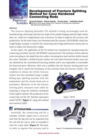
  • 1. Development of Fracture Splitting Method for Case Hardened Connecting Rods Tsuyoshi Kubota Shinya Iwasaki Tsuneo Isobe Toshikatsu Koike ●Advanced Technology Research Div. Research & Development�Operations / Manufacturing Engineering Div. Abstract The fracture splitting (hereafter FS) method is being increasingly used for manufacturing connecting rods that are made of the powder forging material, high-carbon steel, etc., which are comparatively easy to fracture, in order to improve the accuracy and productivity. On the other hand, case hardened steel (for instance, JIS SCM420), which has a high fatigue strength, is used for the connecting rod in high performance motorcycles in order to reduce the motorcycle's weight. In this report, the application of the FS method was examined for manufacturing the connecting rod which used the JIS SCM420 carburized steel. The hardness of this material varies according to the depth from the surface, becoming less hard and less brittle toward the center. Therefore, a brittle fracture surface over the entire fractured surface area was not obtained by the conventional fracturing method, and it was impossible to reassemble the fractured parts. Moreover, there was a problem that the fracture starting point was irregular and it caused the breakaway of tiny fractions from the fracture surface. The condition to obtain the brittle fracture surface was then elucidated using a weight falling-type splitting machine with the temperature and the virtual strain rate as parameters. Moreover, as for the fracture starting point, measures were taken by analyzing it using the nonlinear simulation of the explicit method. The production of the connecting rod for the Yamaha supersport model YZF-R1(Figure 1)using this method was started in 2003. � INTRODUCTION Generally, the connecting rod for a multiple cylinder engine has a structure such that the big end can be separated into the rod and the cap in order to assemble it with the crank shaft (Figure 2). Recently, in order to improve the accuracy and to Figure 1. YZF-R1 Figure 2. FS carburized connecting rod 2005.04.06 Technical Papersand Articles YAMAHA MOTOR TECHNICAL REVIEWYAMAHA MOTOR TECHNICAL REVIEW
  • 2. decrease the manufacturing cost for the connecting rod having such a structure, the Fracture Splitting (FS) method has attracted attention, and its adoption is being seriously considered. In the FS method, the cap and the rod are forged and machined in the form of one body, and then the body is separated into two pieces by making an impact, forming a notch groove at the inside diameter of the big end as the crack initiation point. As a result, the machining for positioning becomes unnecessary because precise positioning during assembling becomes possible by having the fractured surface face each other. Reduction of the production cost becomes possible by applying this method due to the integration of the machining processes of the cap and the rod and the elimination of machining the end face and positioning. Moreover, the efficacy of improving the reliability and decreasing the power loss is expected because the accuracy of the inside diameter of the big end is improved due to the improvement in the positioning accuracy between the cap and the rod. The application of the FS method for the production of the connecting rod using sintered forged steel was started in the 1990's [1]. The applications of the FS method for the connecting rod using a high fatigue strength material were then examined due to the requirement of improving the engine performance and the fuel economy. Olaniran et al.[2] and Repgen[3] developed a method for applying the FS method to forging steels, which have a higher fatigue strength compared to the sintered forged steel. Furthermore, Fukuda et al.[4], Inoue et al.[5] and Park et al.[6] developed a method for applying the FS method to microalloyed steel, which excels in fatigue strength and machinability among the forging steels. The microalloyed steel developed by Inoue et al. exhibited a fatigue limit that reached 480MPa. All these materials had improved cracking capability due to the increase in the brittleness while maintaining or improving the fatigue strengths, therefore, the application of the FS method was enabled. On the other hand, as for the heat treatment, the quenching and the tempering is effective for obtaining forging steels with a higher fatigue strength. In particular, the carburizing quenching and tempering of the low carbon case hardening steel is widely used for the connecting rod of high performance small engines in view of the balance of Forging Machining Carburizing, quenching and tempering Fracture Splitting (FS) Assembly of cap and rod Grinding Separation of cap from rod Assembly with crank shaft Figure 3. Fabrication process for carburized FS connecting rods Development of Fracture Splitting Method for Case Hardened Connecting RodsTechnical Papersand Articles Technical Papersand Articles YAMAHA MOTOR TECHNICAL REVIEWYAMAHA MOTOR TECHNICAL REVIEW
  • 3. machining ease before the heat treatment and the high fatigue strength and toughness after the heat treatment. In this report, the application of the FS method was examined for connecting rods made of carburized quenched and tempered steel of JIS SCM420 (effective hardening depth: 0.5mm, fatigue limit: 800MPa, hereafter abbreviated as SCM420 carburized steel), which is generally used for large volume displacement motorcycle engines. The properties of this material are the hardness changes in accordance with the depth, and the hardness and the brittleness are lower on the inside. Therefore, there were some problems such that a brittle fracture was not obtained for all the fracture surfaces and the mode of the fracture was irregular. Consequently, these two problems were examined. � CONDITIONS OF OBTAINING BRITTLENESS FRACTURE SURFACE 2.1 Target One of the properties required for the FS method is that the shape and the dimensions of the connecting rod after assembly do not change during processing. Moreover, it is required to have a precise positioning within microns by facing the fracture surface in order to assemble the cap and the rod. Therefore, the fracture surface is required to undergo brittle fracture, and various examinations were carried out on the characteristics of the material and the fracture conditions [2-6]. In the vicinity of the surface of the SCM420 carburized steel, it is easy to obtain a brittle fracture due to the high carbon and high hardness. However, on the inside, it is expected that the brittle fracture is not easily obtained compared to the material examined up to now because of the low carbon and low brittleness. For instance, the Charpy impact value of the JIS3 test specimen was 19-23 J/cm2 for the forging steels [5], which has been evaluated for the FS method, while it is 59J/cm2 or more for the inside of this material [7]. The fracture condition for obtaining the brittle fracture over the fracture surface including the inside was examined for the SCM420 carburized steel. Development of Fracture Splitting Method for Case Hardened Connecting RodsTechnical Papersand Articles Technical Papersand Articles YAMAHA MOTOR TECHNICAL REVIEWYAMAHA MOTOR TECHNICAL REVIEW
  • 4. 2.2 Experimental procedure Concerning the fracture conditions, it is postulated that the condition required for the actual connecting rod cannot be reproduced by the standardized test method such as the Charpy impact test, etc. The test method similar to the production method was done using the actual connecting rod as the test piece in order to reflect the results obtained under production conditions. A schematic drawing of the test method is shown in Figure 4. The test piece was prepared by the following method: the JIS SCM420 material was hot forged into the shape of the connecting rod, and after the machining was completed, it was subjected to carburizing, quenching and tempering. The distribution of the hardness is shown in Figure 5. Grooves for the crack initiation were formed by electric discharge machining on the inner surface of the big end. The shape of the grooves is shown in Figure 6. L Free fallDropping height (Hwt1) θ = 4° θ = 4° Connecting rod Wedge Weight (mass: Mwt) Wedge (mass: Mwg) Weight (mass: Mwt) Slider 1 Slider 2 Connecting rod stress concentration factor : α Maximum height of the weight and the wedge after cracking Initial position Initial position of the wedge Maximum height of the weight (Hwt2) Maximum height of the wedge (Hwg2) Figure 4. Connecting rod and jigs for FS experiments 300 400 500 600 700 800 0 0.2 0.4 0.6 0.8 1 1.2 1.61.4 Vickershardness/HV0.3 Distance from surface / mm Figure 5. Hardness of specimen Figure 6. Shape and dimension of the groove Development of Fracture Splitting Method for Case Hardened Connecting RodsTechnical Papersand Articles Technical Papersand Articles YAMAHA MOTOR TECHNICAL REVIEWYAMAHA MOTOR TECHNICAL REVIEW
  • 5. It is considered that a significant energy is required for fracture of the SCM420 carburized steel compared with the conventional material. In order to examine the fracture conditions of such a material, a falling weight type splitting machine was used. As shown in Figure 4, the potential energy of the weight is given to the wedge, and the wedge opens the slider in the direction of the axis of the connecting rod, and it breaks the big end of the connecting rod. After fracturing, the weight is repelled up with the damper. This splitting machine can produce a larger energy and larger distortion velocity compared to the splitting machine activated by an oil hydraulic press, crank press, etc. Furthermore, the rate of strain and the energy can be easily adjusted by changing the mass of the weight and its falling height. In this test method, the brittleness transition of the fracture surface cannot be measured by a method like the Charpy impact test, etc., because the energy absorption due to the friction of the jig, etc., cannot be accurately calculated. Two parameters of the "Quasi- Absorbed Energy" and the "Quasi-strain ratio" were then defined for this test method. The Quasi-Absorbed Energy is the total sum of the energy, which was absorbed by the connecting rod and the jig during fracturing, and is defined as follows: E= MwtgHwt1-MwtgHwt2-MwggHwg2 (1) where Mwt is the mass of the weight, Mwg is the mass of the wedge, g is the gravitational acceleration, Hwt1 is the initial height of the weight, Hwt2 is the maximum height of the weight after the fracture, and Hwg2 is the maximum height of the wedge (Figure 4). The height of the weight and the height of the wedge were measured by a laser displacement meter. Moreover, the Quasi-strain ratio was defined by the next equation. S =    α (2) 2Vwgtan4°   L where Vwg is the maximum velocity of the wedge, α is the stress concentration factor at the bottom of the grooves starting the fracture, and L is the distance between the working points of the slider (Figure 4). The fracture surface was observed by SEM (Scaninng Electron Microscope) as a method for determining the brittleness/ductility of the fracture surface. The one, which exhibited a cleavage fracture surface over the entire fracture surface of the connecting rod as shown in Figure 7a, was defined as having a brittle fracture surface, and the one, which exhibited dimples as shown in Figure 7b, was defined as having a ductile fracture surface. Figure 7. Fracture Surfaces a. Cleavage fracture b. Dimple Development of Fracture Splitting Method for Case Hardened Connecting RodsTechnical Papersand Articles Technical Papersand Articles YAMAHA MOTOR TECHNICAL REVIEWYAMAHA MOTOR TECHNICAL REVIEW
  • 6. 2.3 Results Figure 8 shows the relations between the fracture temperature and the Quasi- Absorbed Energy examined at the Quasi- strain ratio of 10 sec-1 . The fractography varied at the temperature of 230K and the Quasi-Absorbed Energy of about 45J. The ductile-brittle transition temperature in this test method is considered to be 230K at the Quasi-strain ratio of 10 sec-1 . The relations between the fracture temperature and the Quasi-strain ratio are shown in Figure 9. Under the condition of the Quasi- strain ratio of 7.5 sec-1 or less (broken line), it was impossible to stably obtain a brittle fracture surface regardless of the fracture temperature. At the higher Quasi-strain ratio, changes in the fractography were observed as indicated by the alternate long and short dashed line. These two borders are the ductile-brittle transition lines, which indicates the condition in order to obtain a brittle fracture surface by this test method. 10 20 30 40 50 60 70 150 200 250 300 Quasi-absorbedenergy/J Temperature/K Brittle fracture Ductile fracture Figure 8. Relationship between temperature and Quasi-Absorbed Energy 3 6 9 12 150 190 230 270 Quasi-strainratio/sec-1 Temperature/K Brittle fracture Ductile fracture Figure 9. Relationship between temperature and Quasi-strain ratio Development of Fracture Splitting Method for Case Hardened Connecting RodsTechnical Papersand Articles Technical Papersand Articles YAMAHA MOTOR TECHNICAL REVIEWYAMAHA MOTOR TECHNICAL REVIEW
  • 7. � CAUSES AND MEASURES OF MULTIPLE FRACTURE SURFACE OCCURRENCES 3.1 Target Among the connecting rods, which had the brittle fracture surface, gaps were observed in three areas, i.e., (i), (ii), and (iii) in Figure 10. These gaps occurred by the overlapping of multiple fracture surfaces as shown in Figures 11 and 12. As for gap (iii), it was confirmed not to be a problem for manufacturing and use. However, as for gaps (i) and (ii), there is the possibility of producing a tiny fraction during the processing when the machining allowance for chamfering and grinding overlaps with the gap as shown in Figure 12. This tiny fraction separates from the fracture surface when the cap and rod are separated. Afterwards, it is likely to become a problem when in use as for the inclusion in engine oil or it becomes the cause of defective assembly due to sticking between the two fracture surfaces during assembly of the crank. Therefore, it is necessary to investigate the cause of these cracks and then prevent the occurrence of such gaps. 3.2 Experimental procedure In order to investigate the cause of the multiple fracture surface, a nonlinear simulation of the explicit method, which could calculate the high-speed impact phenomenon, was carried out. The stress that was generated at the cross section was analyzed, and the portion where there was the possibility of starting a fracture was investigated. LS-DYNA960 was used as the ( ii ) Fracture AFracture A Fracture BFracture B GrindingChamfering Figure 11. Enlargement of Figure.10(ii) Fracture A Fracture B The gap Chamfering and grinding Tiny fraction Cap Rod Assembly of cap and rod Separation of cap from rod Figure 12. Schematic cross section of the gap ( i ) ( ii ) ( iii ) Figure 10. The gap in the fracture surface Development of Fracture Splitting Method for Case Hardened Connecting RodsTechnical Papersand Articles Technical Papersand Articles YAMAHA MOTOR TECHNICAL REVIEWYAMAHA MOTOR TECHNICAL REVIEW
  • 8. solver. A half size model was selected by taking the symmetry of the entire body into consideration. The general view is shown in Figure 13. The point at which the weight came in contact with the wedge was defined as the starting time, and the initial velocity of the weight was assumed to be 650 mm/sec. Moreover, the calculation was carried out by assuming that the wedge and the slider were solid bodies. For the shape of the connecting rod, the calculation was carried out for the shape such that the groove of the crack initiation point at the edge was removed, besides the current shape. (Figure 15) 3.3 Results The results of the stress analysis by the simulation ares shown in Figure 14. The stress was concentrated at 3 points (a, b, and c) in the figure, and the possibility that these gaps independently became the crack initiation points was confirmed. It is considered that gaps (i) and (ii) occurred by joining of the fracture surfaces, which started at the stress concentration zones of points a and b, and points b and c, respectively. The crack initiation point grooves at points a and c were then removed in order to decrease the stress concentration in this area (Figure 15), and the simulation was carried out again. As a result, it was confirmed that the stress concentration at points a and c were relaxed as shown in Figure 16. The connecting rod having this shape was experimentally manufactured and Wedge mass:13.2kg gravity force:9800mm/sec2 Weight mass:200kg initial speed:650 mm/sec gravity force:9800mm/sec2 Figure 13. FEM simulation of the FS method Figure 15. Machining shape of the cross section Figure 16. Stress distribution in the cross section a b c b. after removala. before removal a b c Figure 14. Stress distribution in the cross section a b c Development of Fracture Splitting Method for Case Hardened Connecting RodsTechnical Papersand Articles Technical Papersand Articles YAMAHA MOTOR TECHNICAL REVIEWYAMAHA MOTOR TECHNICAL REVIEW
  • 9. tested. No fracture surface that originated at points a and c was observed as shown in Figure 17, and it was confirmed that the occurrence of gaps (i) and (ii) could be prevented. As a result, it was confirmed that the tiny fractions did not occur during the processing after the splitting. � CONCLUSION Two problems were examined for use of the FS method for making connecting rods using SCM420 carburized steel. 1. It was found that the temperature and the Quasi-strain ratio affected the brittleness of the fracture surface, and the ductile-brittle transition line was selected as the variable in order to determine the condition for obtaining a brittle fracture surface. 2. Concerning the cause of the multiple fracture surface and the efficacy of its measures, it was found that they could be investigated by a nonlinear simulation. As a result, the occurrence of the tiny fractions during the processing after the splitting could be prevented. Consequently, the application of the FS method for making the connecting rod, which used SCM420 carburized steel with the fatigue limit of 800Mpa, became possible, and increased the efficacy of reliability improvement by improving the accuracy of the big end part with about a 30% reduction in the production cost for small high performance motorcycle engines. The production of the connecting rod for the supersport model YZF-R1 using this method was begun in 2003. Figure 17. Fracture surface after stress reduction Development of Fracture Splitting Method for Case Hardened Connecting RodsTechnical Papersand Articles Technical Papersand Articles YAMAHA MOTOR TECHNICAL REVIEWYAMAHA MOTOR TECHNICAL REVIEW
  • 10. ■REFERENCES [1] M. Weber; SAE Technical Paper Series, No.910157(1991). [2] M. A. Olaniran, C. A. Stickels; SAE Technical Paper Series, No.980033 (1993). [3] B. Repgen; SAE Technical Paper Series, No.980882 (1998). [4] S. Fukuda, H. Etou; Conference Proceedings of the Society of Automotive Engineers of Japan, No. 86-00, 13 (2000). [5] K. Inoue, S. Nakamura; Electric Furnace Steel, 71-1, 81 (2000). [6] H. Parks, Y. S. Ko, S. C. Jung, B. T. Song, Y. H. Jun, B. C. Lee and J. D. Lim; SAE Technical Paper Series, No.2003-01-1309 (2003). [7] JIS G4105. ■AUTHORS   Tsuyoshi Kubota   Shinya Iwasaki   Tsuneo Isobe   Toshikatsu Koike Development of Fracture Splitting Method for Case Hardened Connecting RodsTechnical Papersand Articles Technical Papersand Articles YAMAHA MOTOR TECHNICAL REVIEWYAMAHA MOTOR TECHNICAL REVIEW