Download to read offline
![Section 6 – Steel Structures (SI)
C6 - 10
The form of the width-to-thickness
equations derives from the classical elastic
critical stress formula for plates: Fcr =
[π2
kE]/[12(1-2
)(b/t)2
], in which the buckling
coefficient, k, is a function of loading and
support conditions. For a long, uniformly
compressed plate with one longitudinal edge
simply supported against rotation and the other
free, k = 0.425, and for both edges simply
supported, k = 4.00 (Timoshenko and Gere
1961). For these conditions, the coefficients of
the b/t equation become 0.620 and 1.90l,
respectively. The coefficients specified herein
are the result of further analyses and numerous
tests and reflect the effect of residual stresses,
initial imperfections, and actual (as opposed to
ideal) support conditions.
The Specified minimum wall
thicknesses of tubing are identical to those of the
1995 AC1 Building Code. Their purpose is to
prevent buckling of the steel pipe or tubing
before yielding.
C6.9.5.1
The procedure for the design of
composite columns is the same as that for the
design of steel columns, except that the yield
strength of structural steel, the modulus of
elasticity of steel, and the radius of gyration of
the steel section are modified to account for the
effect of concrete and of longitudinal reinforcing
bars. Explanation of the origin of these
modifications and comparison of the design
procedure, with the results of numerous tests,
may be found in SSRC Task Group 20 (1979)
and Galambos and Chapuis (1980).
C6.9.5.2.1
Little of the test data supporting the
development of the present provisions for design
of composite columns involved concrete
strengths in excess of 40 MPa. Normal density
concrete was believed to have been used in all
tests. A lower limit of 20 MPa is specified to
encourage the use of good-quality concrete.
C6.9.5.2.3
Concrete-encased shapes are not subject
to the width/thickness limitations specified in
Article 6.9.4.2 because it has been shown that
the concrete provides adequate support against
local buckling.
C6.10.1
Noncomposite sections are not
recommended but are permitted.
C6.10.2.1
The ratio of Iyc/Iy determines the
location of the shear center of a singly
symmetric section. Girders with ratios outside of
the limits specified are like a "T" section with
the shear center located at the intersection of the
larger flange and the web. The formulas for
lateral torsional buckling used in the
Specification are not valid for such sections.
C6.10.2.2
The specified web slenderness limit for
sections without longitudinal stiffeners
corresponds to the upper limit for transversely
stiffened webs in AASHTO (1996). This limit
defines an upperbound below which fatigue due
to excessive lateral web deflections is not a
consideration (Yen and Mueller 1966; Mueller
and Yen 1968).
The specified web slenderness limit for
longitudinally stiffened webs is retained from
the Load Factor Design portion of AASHTO
(1996). Static tests of large-size late girders
fabricated from A 36 steel with D/tw ratios
greater than 400 have demonstrated the
effectiveness of longitudinal stiffeners in
minimizing lateral web deflections (Cooper
1967). Accordingly, the web slenderness limit
given by Equation 2 is used for girders with
transverse and longitudinal stiffeners. The
specified web slenderness limit is twice that for
girders with transverse stiffeners only. Practical
upper limits are specified on the limiting web
slenderness ratios computed from either
Equation 1 or 2. The upper limits are slightly
above the web slenderness limit computed from
Equation 1 or 2 when fc is taken equal to 250
MPa.](https://image.slidesharecdn.com/section6-200205072202/85/Section-6-steel-nscp-commentary-10-320.jpg)

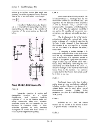
This document summarizes key provisions related to steel structures in Section 6 of the specifications. It discusses how elements are proportioned based on their structural action like tension, compression, flexure, etc. It also discusses requirements for connections, splices, and specific structural types. Key points covered include material properties of steels, fatigue design considerations grouping details into categories, and commentary on orthotropic deck details.