More Related Content
Similar to Rowe matcong (20)
Rowe matcong
- 1. ©TWI and Cedar Metals Ltd. Page 1 of 11
ADVANCES IN TOOLING MATERIALS FOR FRICTION
STIR WELDING
Eur.Ing. C.E.D.Rowe. B.Sc.C.Eng.C.Sci.MIMMM SenMWeldI
Cedar Metals Limited.
and
Eur.Ing. Wayne Thomas MPhil. C.Eng. FWeldI
TWI Cambridge
ABSTRACT.
Since its invention at TWI in 1991, Friction Stir Welding (FSW) has become a
major joining process in the aerospace, railway and ship building industries
especially in the fabrication of aluminium alloys. The process uses a spinning
non-consumable tool to generate frictional heat in the workpiece. Worldwide,
there are now over 135 licensees of FSW and new techniques and
applications are being developed daily. This paper looks at some current
uses, variations in tool design, improved welding techniques and new tool
materials being developed for the welding of more difficult aluminium alloys to
give increased tool life.
- 2. Page 2 of 11 ©TWI and Cedar Metals Ltd.
1. INTRODUCTION
Friction Stir Welding was invented and patented by The Welding Institute in
1991. The process uses a spinning, non-consumable tool, similar to a taper
reamer, to generate frictional heat in the workpiece. By pressing this tool into
contact with a seam to be welded, the base metal heats up and once it
reaches about 80% of its melting point it becomes soft and deforms easily. A
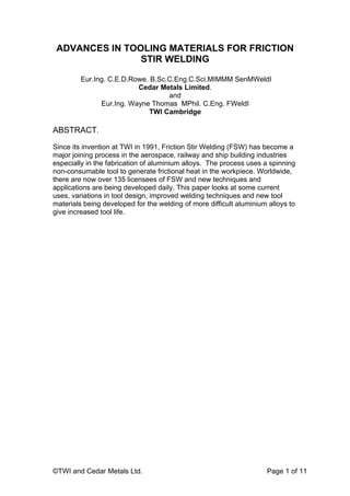
typical FSW system is shown in Fig 11
.
Fig 11
The principle of Friction
Stir Welding
By keeping the tool rotating and moving it along the seam to be joined, the
softened material is literally stirred together forming a weld without melting.
These welds require low energy input and are without the use of filler
materials and distortion. Initially developed for non-ferrous materials such as
aluminium, by using suitable tool materials the use of the process has been
extended to harder and higher melting point materials such as steels titanium
alloys and copper. Since its conception in 1991 there have been considerable
advances in process technology and there are now over 135 licensees of the
process and over 1500 subsidiary patents have been filed. This paper will
concentrate on improvements for tooling for the friction stir welding of
aluminium alloys.
2. COMMERCIALISATION
Boeing in the USA was amongst the first companies to realise the commercial
benefits of the process and used it to fabricate fuel tanks used in its space
programme, Fig 2. By changing from conventional TIG to FSW for the welding
of their rocket fuel tanks, Boeing achieved a staggering 99% reduction in
welding costs. Clearly, the process has excellent possibilities and thus many
licensees are rapidly developing improved tooling and looking for new
applications. In the conventional tungsten inert gas welding process, except in
the case of thin sheet, material is machined from the ends of plates to be
- 3. ©TWI and Cedar Metals Ltd. Page 3 of 11
Fig 2. Rocket fuel tanks fabricated by FSW
joined to form the weld preparation only to be replaced by several runs of filler
material to complete the weld. With FSW, clean cut straight edges are butted
or lapped together, held in position by a suitable clamping arrangement and
welded together purely by running a tool along the seam. The process is now
in regular use in Japan for the production of aluminium railway rolling stock,
Fig 3 and for aluminium ship construction, Fig 4. It is also used to weld
sections of the latest Bang and Olufsen loud speakers.
Fig 3.
Japanese railway
rolling stock
fabricated from
aluminium by FSW.
Fig 4.
Aluminium ships
constructed in Japan
using FSW
- 4. Page 4 of 11 ©TWI and Cedar Metals Ltd.
3. TOOL DESIGN
Tools consist of a shoulder and a probe which can be integral with the
shoulder or as a separate insert possibly of a different material. The design of
the shoulder and of the probe is very important for the quality of the weld. The
probe of the tool generates the heat and stirs the material being welded but
the shoulder also plays an important part by providing additional frictional
treatment as well as preventing the plasticised material from escaping from
the weld region. The plasticised material is extruded from the leading to the
trailing side of the tool but is trapped by the shoulder which moves along the
weld to produce a smooth surface finish. Clearly, different materials and
different thicknesses will require different profile probes and welds can be
produced from just one side or by welding half the thickness then turning over
to complete the other side. Some typical Whorl™ type probes are shown in
Fig 52
which can be designed to weld in excess of 60mm thick plate at higher
speeds than conventional pin type probes.
Fig 5 Basic variants on the Whorl™ type probes2
.
A variation on the Whorl™ probe is the MX-Triflute™ Fig 62
which can
produce a better weld than the Whorl™ tool with a narrower, more parallel
sided weld region.
Fig 6.
A Typical MX-Triflute™ probe2
.
- 5. ©TWI and Cedar Metals Ltd. Page 5 of 11
The improvement can clearly be seen in Figs 7 & 8 of welds in 25mm thick
6082-T6 aluminium alloy welded at 4mm/second. The Whorl™ tool, Fig 7
tending to produce an ‘union ring’ effect whereas the MX-Triflute™ weld Fig 8,
is narrower and more uniform2
.
Advancing side Retreating Side
Fig 7
Macrostructural
features in the weld
region2
. Weld
produced in 6082-T6
condition aluminium
alloy using a Whorl™
probe at a weld travel
speed of 4mm/sec.
Fig 8
Macrostructural
features of a weld as
in Fig 7 but using a
MX-Triflute™ probe a
a weld travel speed of
4mm/sec.2
Retreating Side Advancing Side
Fig 9
Macrosection of a
Lap weld in 6mm
thick 5083-0
condition aluminium
alloy welded at
4mm/sec using a
Flared-Triflute™
tool.2
- 6. Page 6 of 11 ©TWI and Cedar Metals Ltd.
Friction stir welding is also used to carry out lap welds where the plates to be
joined are overlapped and the probe run through the top sheet and into the
bottom as illustrated in Fig 9.
With the lap welds it is desirable to increase the width of the weld region to
achieve a better bond. This is achieved by re-design of the tools as in Flared-
Triflute™ as illustrated in Fig 10.
Fig 10. Basic variants of the Flared-Triflute™ type probes2
.
The fluted tool can have flutes neutral (a), left (b) right (c) handed as
illustrated or a combination of all three at 120º intervals one neutral, one left
and one right on an individual probe (d). The pitch of the ridges is also
important in determining the properties of the tool. The ridges enable
plasticised material to be deflected in the direction required especially to
deflect oxide from the centre of the weld to the surface. To increase the
spread in lap welds still further the probe was angled with respect to the tool
axis in a variant of FSW known as Skew-Stir™ and illustrated in Fig 112
. It
will be seen that the swept region is much larger than with conventional
tooling.
Fig 11. Basic principle of Skew-Stir™ showing different focal points.2
(a) (b) (c) (d)
- 7. ©TWI and Cedar Metals Ltd. Page 7 of 11
Another variation is known as Re-Stir™ which is similar to the conventional
stir welding process but the tool continually reversed throughout the welding
process either within one revolution or after 1 or more full revolutions. This
process is illustrated in Fig 12 and the weld produced in Fig 13.2
Fig 12
The basic principle
of Re-Stir™ showing
the reversal
techniques.2
Fig 13
Macrostructure of a Re-
Stir™ butt weld produced
at a weld travel speed of
4.2mm/sec using 8
revolutions per interval.2
Further variations being investigated involve a separate shoulder and probe
both being rotated in the same direction but at different speeds.
Clearly, the variations in tool design are infinite and combinations of shoulder
diameter, shoulder profile, probe length, diameter and profile, are all important
parameters in determining the speed of welding and the quality of the finished
weld. Another important parameter in the determination of the suitability of a
tool for a particular application is the tool material itself. Welding is carried out
around 70 – 90% of the material melting point so it is important that the tool
material has sufficient strength at this temperature otherwise the tool can twist
and break. With conventional aluminium alloys tools made of tool steel give
good results but with the harder alloys something stronger is required. Such
as super alloys, oxide dispersion strengthened alloys (ODS) and refractory
- 8. Page 8 of 11 ©TWI and Cedar Metals Ltd.
metals such as molybdenum alloys. However, although these materials have
superior melting properties they are more difficult to fabricate especially into
some of the complex shapes described above. Difficulties in fabrication lead
to increased tool cost and it is often desirable to sacrifice some durability for a
reasonably priced tool. In an ideal world the user requires to produce very
long welds without tool wear or degradation occurring so some of the more
exotic materials and designs could see increased usage.
Fig 14
Welding 40mm thick
6082 aluminium
alloy using a
molybdenum probe.
Fig 15
A molybdenum tool of basic design
after welding 40mm thick 6082 alloy as
in Fig 14. No tool wear occurred.
Fig 14 shows a basic molybdenum tool welding 40mm thick 6082 alloy.
Because molybdenum has a fibrous structure with the fibres running parallel
to the tool axis, the design of the tool must be simplified to avoid thin sections
and sharp angles. However, the material shows promise and an excellent
weld was produced with no tool wear being observed. The probe after
removal from the weld is shown in Fig 15.
On removal of any FSW probe from the weld, a hole is left. There are several
ways of dealing with this. It can be filled in with conventional TIG filler, the part
of the weld with the hole can be cut off and discarded, or the weld can be run
off into a scrap piece of material which is then discarded. Another method is
to gradually remove the probe at the end of the weld but this is not
recommended as a full penetration weld is not then produced in this region.
- 9. ©TWI and Cedar Metals Ltd. Page 9 of 11
3. OTHER VARIANTS OR TWIN STIR™
A problem occurring with conventional friction stir welding is that the plates to
be joined require extensive clamping both in the vertical and horizontal
directions to prevent them being separated by the rotating probe instead of
being welded. A new process has recently been invented by TWI in which
two contra rotating probes are used to carry out the weld2, 3
. These can be in
tandem as illustrated in Fig 16, especially useful for lap welding or one on
each side of the weld as in Fig 17.
Parallel side-by-side transverse
to the welding direction.
Tandem in-line with the welding
direction.
Staggered to ensure the edges
of the weld regions partially
overlap.
Fig 16. Twin-Stir™ variants2,3
.
Fig 173
.
Simultaneous double side stir
techniques with contra-
rotating probes.
- 10. Page 10 of 11 ©TWI and Cedar Metals Ltd.
The weld head used is illustrated in Fig 181,3
.
Fig 18
Twin-stir™ prototype head
assembly1
.
Which ever technique is used the torque generated by one tool is
counteracted by the other and very little clamping pressure is required to keep
the plates in position for welding. The distance between the tools also helps to
fix the position. This process is known as Twin-Stir™ minimises complex
clamping arrangements and opens the door to producing very large plates,
perhaps the whole plate for a ship’s hull can be produced in one piece and
then fabricated to shape. Currently the sizes of the clamping arrangements
determine the size of welded structure and, although length of plate is no
longer a problem, the plate being passed between the clamps after welding to
allow location and clamping of the next section, the actual width of the clamps
must be of a finite size so there is a restriction in the maximum width of plate
producible. With Twin-Stir™ many of the clamps can be replaced with simple
conventional tack welds. The welds produced are excellent. Fig 191
shows the
surface of a typical Tandem Twin-Stir™ lap weld in 6083-T6 aluminium alloy
and Fig 201
the cross section.
Fig 193
The surface of a typical
tandem Twin-stir™ weld in
6082-T6 aluminium alloy1
.
Fig 203
Macrosection of Tandem
Twin-stir™ weld in 6mm thick
6082-T6 aluminium alloy1
.
- 11. ©TWI and Cedar Metals Ltd. Page 11 of 11
However, one disadvantage of Twin-Stir™ is that there are two exit holes
produced instead of one, Fig 211,3
, which require treatment as outlined above.
Fig 211,3
Tandem Twin-stir™ lead and
follower exit holes1
.
4. DISCUSSION AND CONCLUSION
Friction stir welding is an exciting process for welding pieces of material
together as it requires little or no weld preparation, operates at relatively low
temperatures so gives off no fumes, is environmentally friendly, energy
efficient and can be used by only semi-skilled personnel to produce a
satisfactory weld. The process is suitable for welding plate, pipe or
fabrications and has been used to build up components of complex shape but
this is the topic of another paper. As TIG and MIG welding processes replaced
most of the original stick welding operations in the past, it is envisaged that
FSW will displace many of the current TIG or MIG welding applications with
reduced costs and superior weld quality. As the welding is carried out below
the melting point of the material there is minimum heat affected zone with the
reduced ductility as observed with conventional techniques. This can be
particularly advantageous with some aluminium alloys as segregation can
occur when the material is melted using conventional welding techniques.
5. ACKNOWLEDGEMENTS
D.G Staines of TWI for help in evaluating tool designs and materials.
6. REFERENCES
1. Friction Stir Welding – Process Developments and Variant
Techniques. W.M.Thomas, I.M. Norris, D.G. Staines and E.R.
Watts. Paper presented at SME Summit, Oconomowoc Milwaukee
USA Aug 3rd
– 4th
2005.
2. Friction Stir Welding – An Update on Recent Developments.
W.M. Thomas, S.A. Lockyer, S.W.Kalee and D.G. Staines. From a
paper presented at ImechE Stressed Components in Aluminium
Alloys 2nd
April 2003. Birmingham UK.
3. The Simultaneous use of Two or More Friction Stir Welding
Tools. W.M. Thomas, D.G. Staines, E.R. Watts and I.M. Norris.
Internet publication by TWI 13th
January 2005.