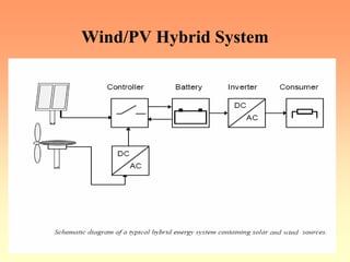
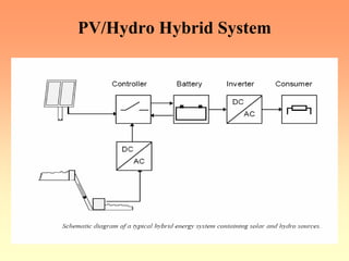
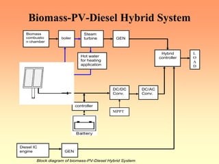
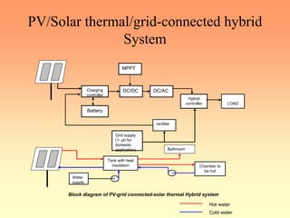
This document discusses various types of hybrid energy systems that combine renewable and conventional energy sources. It begins by introducing hybrid systems and their benefits in addressing power shortage issues in India. It then provides examples of different hybrid combinations, including wind/PV, PV/hydro, biomass-PV-diesel, and PV/solar thermal/grid-connected systems. For each type of hybrid system, it outlines the basic configuration and operating principles. It also includes equations and calculations for estimating power output from various renewable sources and sizing the system components.

![Calculation For Power Output From
Different Source
¾ Normally this angle is equal to the latitude of the concern
place.
¾ The related equation for estimation of the radiation is listed
below [1]:
• Isolation ‘i =Io{ cos ϕ cos δ cos ω + sin ϕ sin δ } kW/m2
• Io = Isc [1 + 0.033 cos (360N/365)] where Isc solar constant.
=1.37 kW/m2
wss
o
wsr
H 'idt
= ∫
ωsr = hour angle when sun rising
ωss = hour angle when sun setting](https://image.slidesharecdn.com/teachslides10-231109012710-21cba3b8/85/teach_slides10-pdf-11-320.jpg)
![Calculation For Power Output From
Different Source-1
• = (24/π) Isc [1+ 0.033 cos (360N/365)] {cos ϕ cos δ cos ω
+ sin ϕ sin δ} kWh/m2/day
• HoA= energy falling on the concern place considering
atmospheric effect
= KT Ho kWh/m2/day where KT dearness index.
• KT = A1 + A2 sin (t) + A3 sin (2t) + A4sin (3t) + A5 cos (t)
+ A6 cos (2t) + A7 cos (3t)
t = (2π/365) (N-80) N= 1 for Jan 1st](https://image.slidesharecdn.com/teachslides10-231109012710-21cba3b8/85/teach_slides10-pdf-12-320.jpg)
![Calculation For Power Output From
Different Source-2
• Ai = ai1 + ai2 x + ai3 x2 + ai4 w + ai5 w2
Where x = (ϕ - 35)
ϕ = Latitude in deg
w = total perceptible water vapor in atoms gm/cm2
• Ht = energy falling on the tilt surface at the concern place
= RD HoA kWh/m2/d
• RD = tilted factor
for the sizing the PV panel is given by[1]
Wpeak = {1/ hpeak } [ (Wh((load) * No of no sun days / (ηb * no of
discharging .Days)) + Whload(day) + Whload(night)/ ηb)]
• Where: ηb = battery efficiency
• hpeak = no of hours for which peak insolation falls on the
PV cell](https://image.slidesharecdn.com/teachslides10-231109012710-21cba3b8/85/teach_slides10-pdf-13-320.jpg)
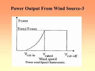
![Power Output From Wind Source
¾ The speed of wind is a random process; therefore it should be
described in terms of statistical methods.
¾ The wind speed data were recorded near the ground surface.
¾ To upgrade wind speed data to a particular hub height, the
following equation is commonly used [2]
v = vi- (H/Hi)α
• Where: v-wind speed at projected height, H
• vi-wind speed at reference height, Hi
• α- Power-law exponent (- 1/7 for open land).](https://image.slidesharecdn.com/teachslides10-231109012710-21cba3b8/85/teach_slides10-pdf-14-320.jpg)
![Power Output From Wind Source-2
Pw = 0.6 A u3
pa = Pw /A = 0.6u3 = power density (in W/m2) [1]
Pw is the electrical power output of the turbine.
¾ The available wind generator power output is a function of
wind velocity v
( )
( )
3 3
R c1
R ci
3 3
R co
w
R co R
P V V
forV V V
V V
P
P 0 for V V V
⎡ ⎤
−
≥ ≥
⎢ ⎥
−
= ⎢ ⎥
⎢ ⎥
≥ ≥
⎣ ⎦](https://image.slidesharecdn.com/teachslides10-231109012710-21cba3b8/85/teach_slides10-pdf-16-320.jpg)
![Calculation Of The Capacity Of The
Battery Bank-2
¾ When the load demand is greater than the available energy
generated,
¾ The batteries will be discharged by the amount that is needed
to cover the deficit. It can be expressed as follows:
E B(t) = E B(t-1) - { E L(t) /η charging controller – E G(t) }
¾ The energy stored in batteries at any hour t is subject to the
following constraint:
E Bmax ≥ E B(t) ≥ EBmin
¾ That means that batteries should not be over discharged or
overcharged at any time. That protects batteries from being
damaged.[2].](https://image.slidesharecdn.com/teachslides10-231109012710-21cba3b8/85/teach_slides10-pdf-20-320.jpg)
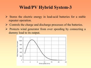
![Wind/PV Hybrid System-4
¾ Initiates the operation of a diesel generator or connects the
system to the electric grid (if available), when the renewable
energy sources fail to produce sufficient electric energy.
¾ Provides continuous and uninterruptible electric power (220
V, 50 Hz) to a 1.5-kW house load.[10]
Local solar radiation information: high, low and average
values of daily solar radiation calculated over one year](https://image.slidesharecdn.com/teachslides10-231109012710-21cba3b8/85/teach_slides10-pdf-27-320.jpg)
![Biomass Energy
¾ Biomass is matter usually thought of as garbage. Some of it is
just stuff lying around -- dead trees, tree branches, yard
clippings, leftover crops, wood chips and bark and sawdust
from lumber mills.
¾ It can even include used tires and livestock manure [5].
¾ The waste wood, tree branches and other scraps are gathered
together in big trucks.
¾ The trucks bring the waste from factories and from farms to a
biomass power plant.
¾ Here the biomass is dumped into huge hoppers. This is then fed
into a furnace where it is burned.](https://image.slidesharecdn.com/teachslides10-231109012710-21cba3b8/85/teach_slides10-pdf-32-320.jpg)
![Biomass Energy-1
¾ Other application of Biomass is that it can also be tapped right
at the landfill with burning waster products.
¾ When garbage decomposes, it gives off methane gas.
¾ Pipelines are put into the landfills and the methane gas can be
collected.
¾ It is then used in power plants to make electricity. or use it for
street lighting.
¾ This type of biomass is called landfill gas[5].
¾ A similar thing can be done at animal feed lots.
¾ In places where lots of animals are raised, the animals - like
cattle, cows and even chickens - produce manure.
¾ When manure decomposes, it also gives off methane gas similar
to garbage.](https://image.slidesharecdn.com/teachslides10-231109012710-21cba3b8/85/teach_slides10-pdf-33-320.jpg)
![About Solar Thermal application
¾ Solar heat is one of the cheapest and most practical forms of
renewable energy.
¾ Here are few of the most common applications:
Solar Hot Water Heaters:
¾ The sun’s light is an excellent source of hot water for home or
commercial use, such as swimming pools, car washes and
Laundromats. [9]
Cooking:
¾ Simple solar ovens and cookers are used around the world in
both commercial kitchens and in people’s homes.
¾ Solar cookers can be made with everyday materials such as
cardboard and tinfoil. [9]](https://image.slidesharecdn.com/teachslides10-231109012710-21cba3b8/85/teach_slides10-pdf-37-320.jpg)


![[doi 10.1002_9781118886502.ch7] Lehr, Jane; Ron, Pralhad -- Foundations of Pu...](https://cdn.slidesharecdn.com/ss_thumbnails/doi10-230810085037-dcf7638a-thumbnail.jpg?width=640&height=640&fit=bounds)