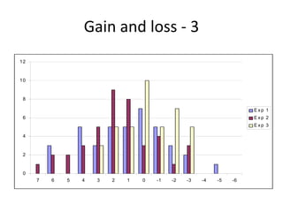
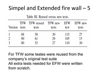
Downloaded 25 times

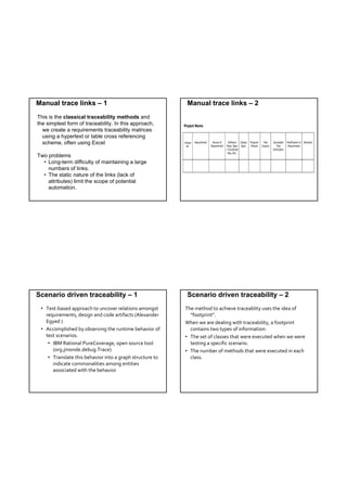
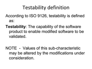
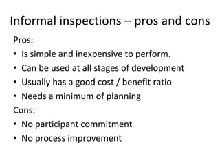
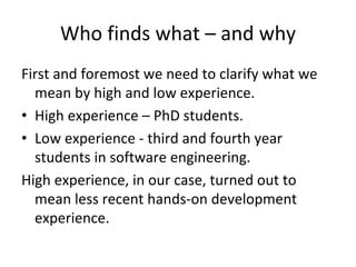
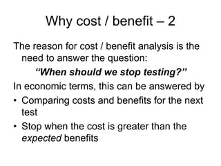
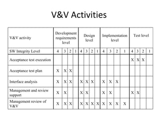
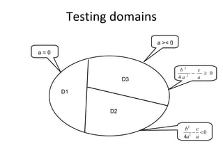
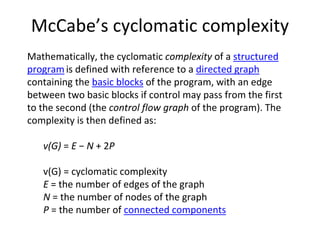
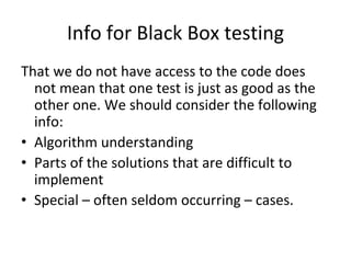
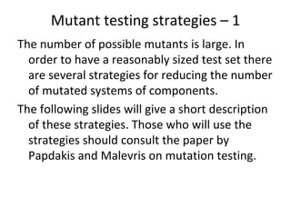
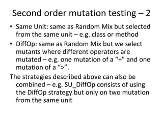
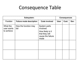
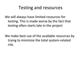
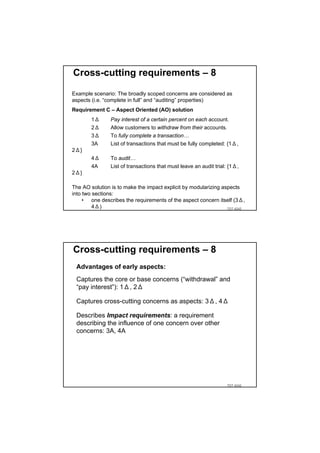
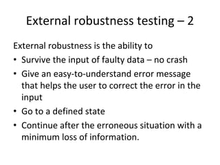
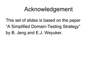
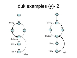
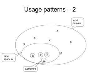
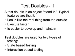
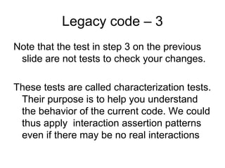
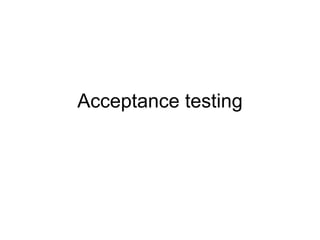
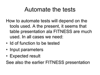
![Footprints – 1 Footprints – 2
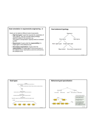
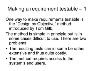
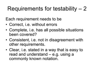
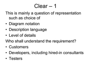
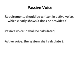
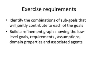
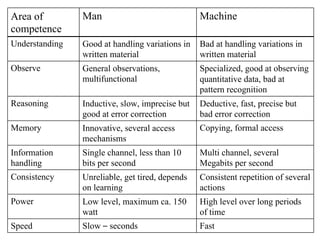
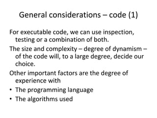
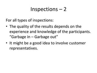
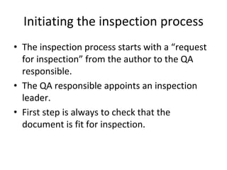
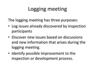
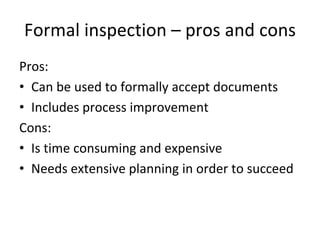
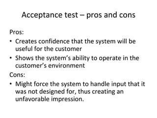
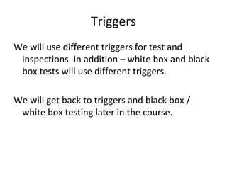
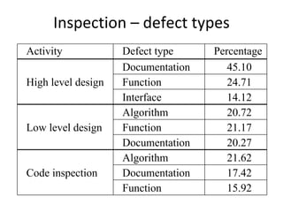
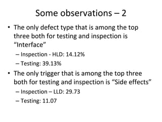
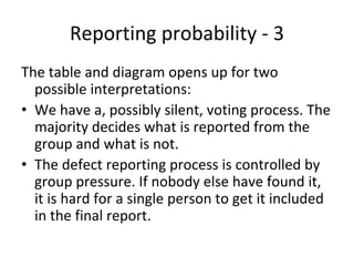
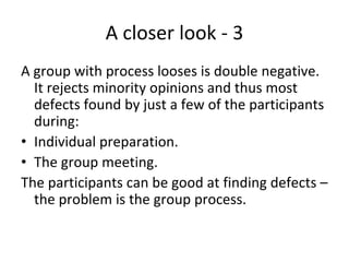
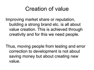
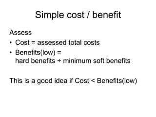
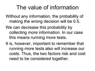
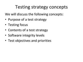
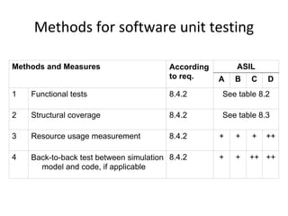
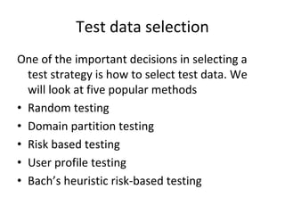
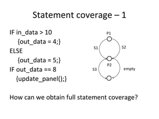
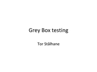
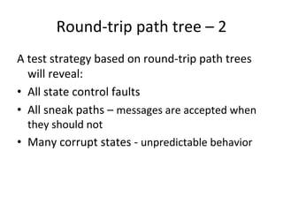
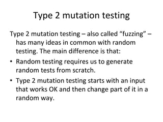
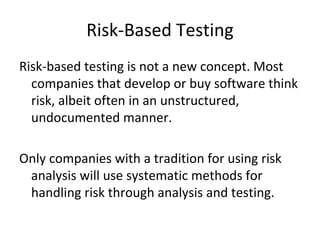
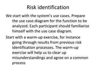
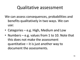
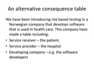
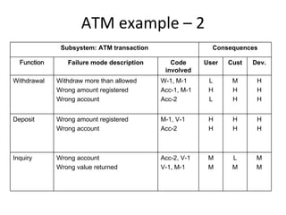
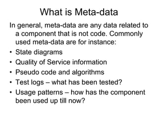
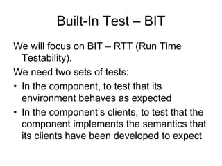
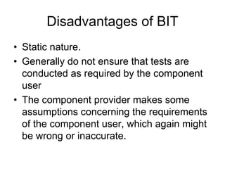
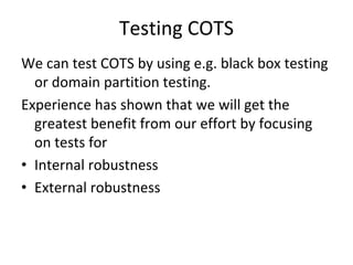
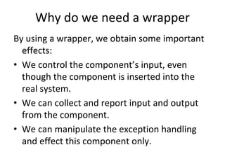
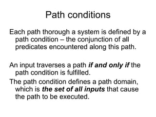
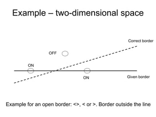
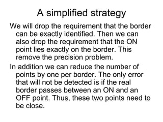
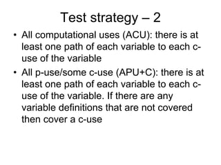
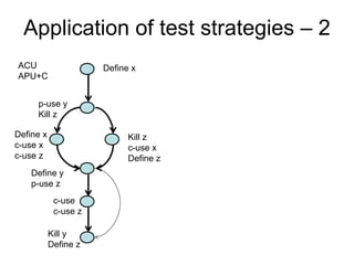
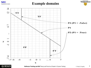
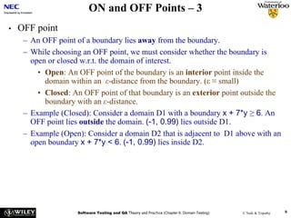
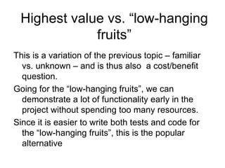
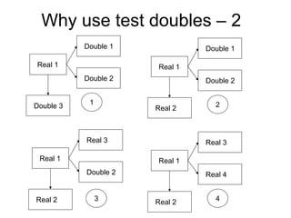
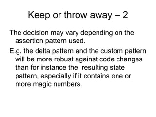
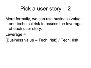
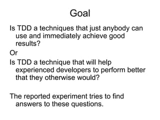
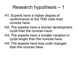
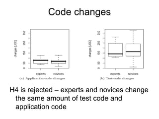
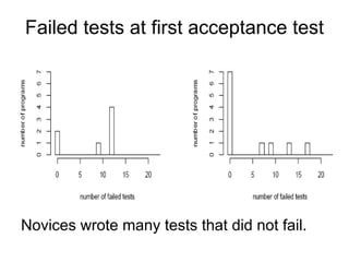
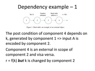
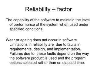
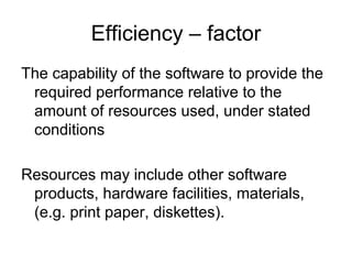
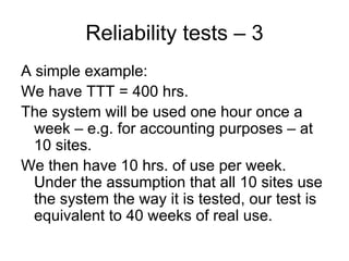
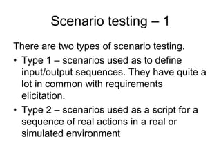
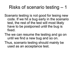
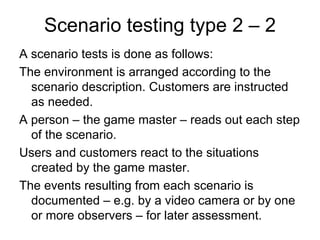
E.g. scenario A uses 10 methods in class CAboutDlg Only classes are registered – e.g scenario [s3] uses
and 3 methods in Csettings Dlg classes C, J, R and U
Footprints – 3 Footprints – 4
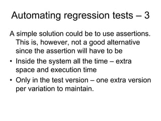
Some problems: Based on the footprint table, we can make a
requirements-to-class trace table
• There might be scenarios that do not cover any
requirement – e.g. [s3]
• There are scenarios that belong to several
requirements, e.g. [s9]
Such scenarios will get separate rows in the trace
matrix and will be marked with an F (Fixed) or a P
(Probable), depending on how sure we are that a
certain class belongs to this scenario.](https://image.slidesharecdn.com/tdt4242-110828132951-phpapp02/85/Tdt4242-30-320.jpg)

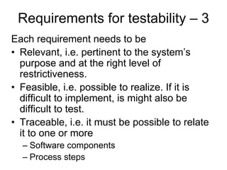


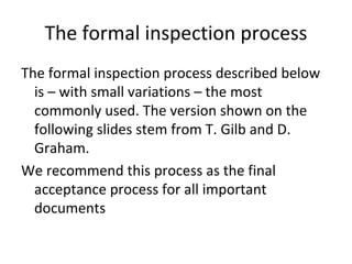
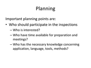
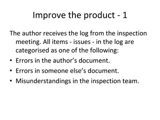
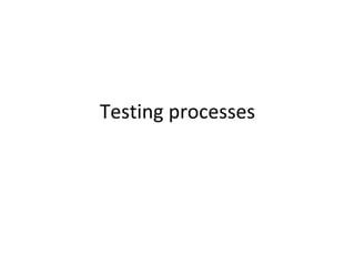

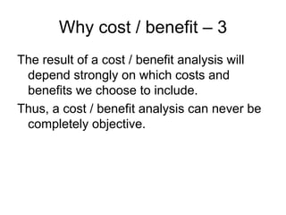
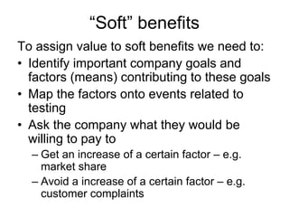
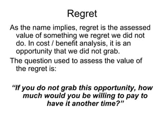

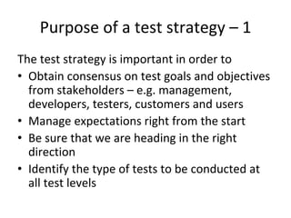

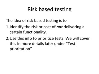
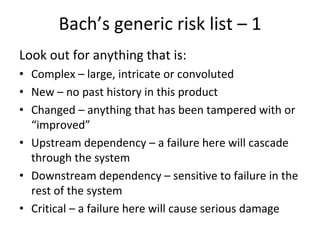


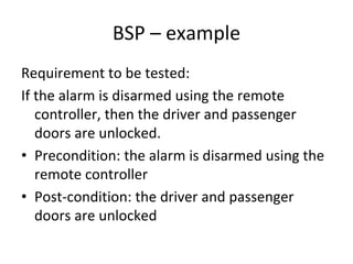
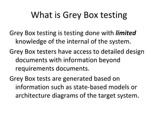
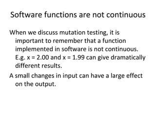
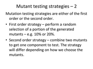
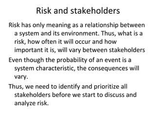
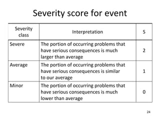
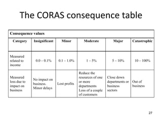
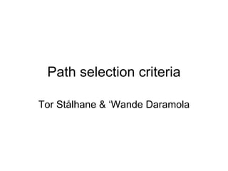
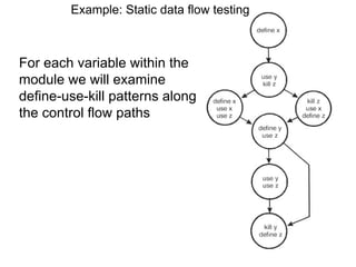
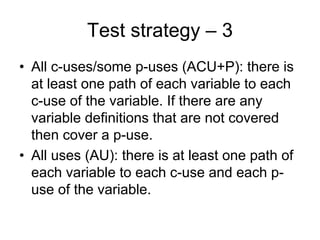
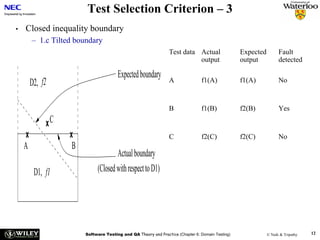
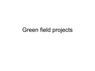
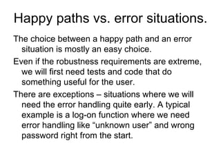
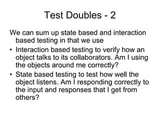
![Basic scenario pattern ‐ BSP
PreCondition == true / {Set activation time}
IsTimeout == true / [report fail]
Check for Check
precondition post-condition
PostCondition == true / [report success]](https://image.slidesharecdn.com/tdt4242-110828132951-phpapp02/85/Tdt4242-242-320.jpg)
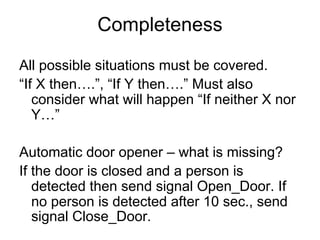
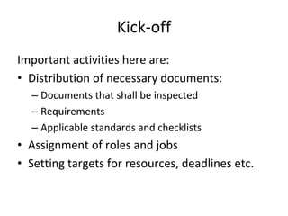
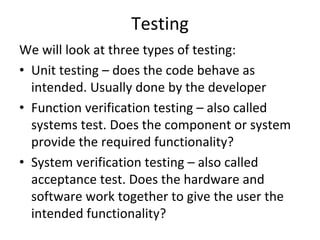
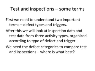
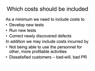
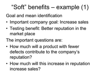
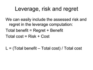
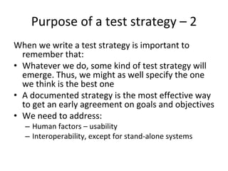
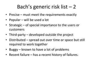
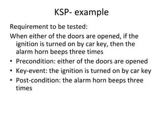
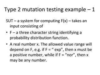
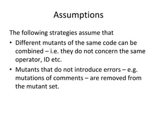
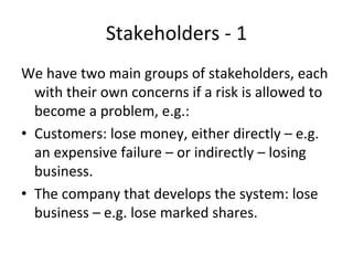
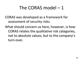
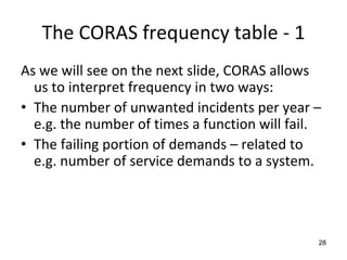
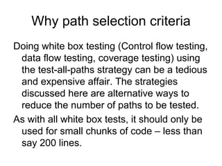
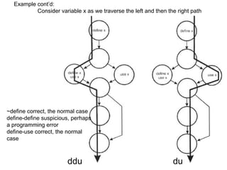
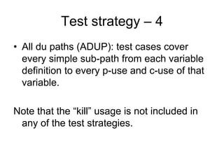
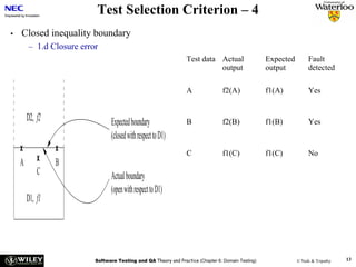
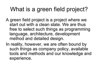
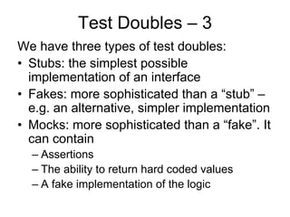
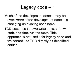
![Key‐event service pattern ‐ KSP
KeyEventOccurred / [SetActivationTime]
Check
precondition
PreCondition == true
Check for key Check
event post-condition
IsTimeout == true / [report fail]
PostCondition == true / [report success]](https://image.slidesharecdn.com/tdt4242-110828132951-phpapp02/85/Tdt4242-244-320.jpg)
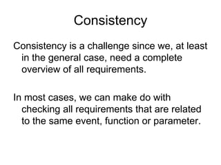
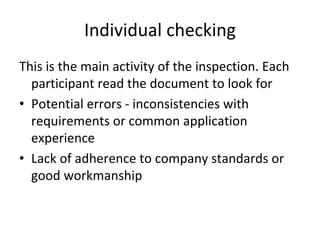
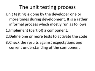
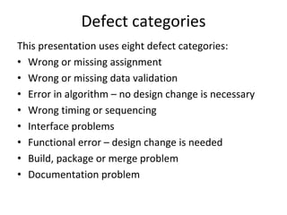
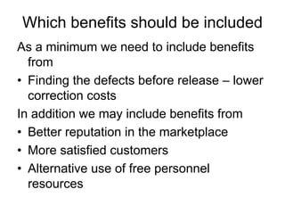
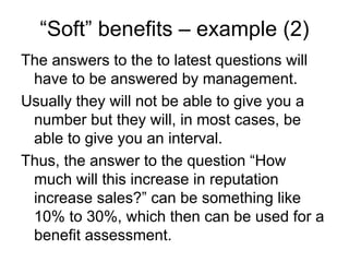
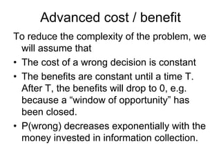
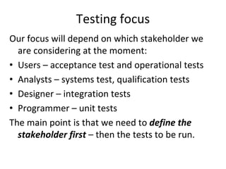
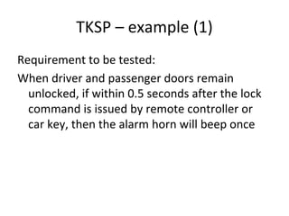
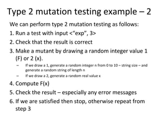
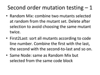
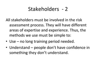
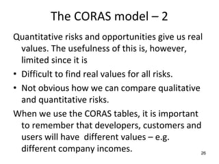
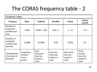
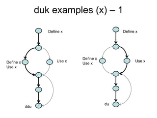
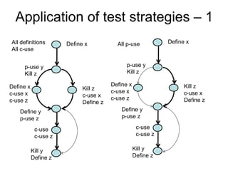
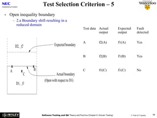
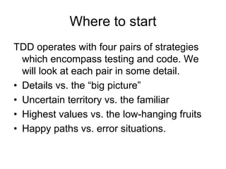
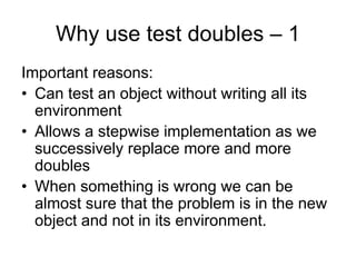
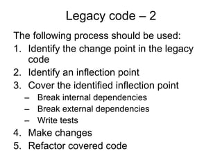
![Timed key‐event service pattern ‐ TKSP
KeyEventOccurred / [SetActivationTime]
Check
precondition
PreCondition == true
DurationExpired /
[report not exercised]
Check for key Check
event post-condition
IsTimeout == true / [report fail]
PostCondition == true / [report success]](https://image.slidesharecdn.com/tdt4242-110828132951-phpapp02/85/Tdt4242-246-320.jpg)
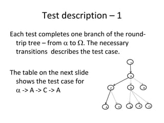
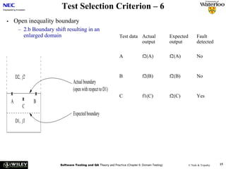
![Round‐trip tree – small example
A
a[p1] / w
A B
a[p1] / w
B A
b[p2] / u
C
b[p2] / u
C
A B A ](https://image.slidesharecdn.com/tdt4242-110828132951-phpapp02/85/Tdt4242-259-320.jpg)
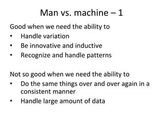
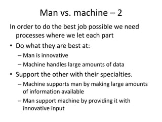
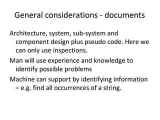
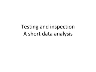
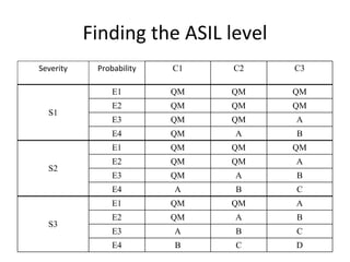
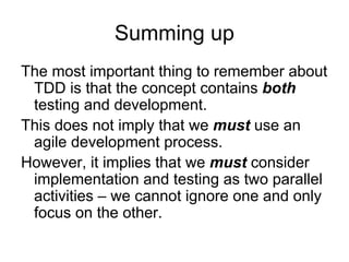
![Transitions
Each transition in a state diagram has the form
trigger‐signature [guard] / activity. All parts are
optional
• trigger‐signature: usually a single event that
triggers a potential change of state.
• guard: a Boolean condition that must be true
for the transition to take place.
• activity: an action that is performed during
the transition.](https://image.slidesharecdn.com/tdt4242-110828132951-phpapp02/85/Tdt4242-260-320.jpg)
![Test description – 2
ID Start Event Condition Reaction New
state state
1 constructor - - A
2 A a p1 w C
3 C b p2 u A
a[p1] / w
A
A B
B A
b[p2] / u
C
a[p1] / w
b[p2] / u
C A B A](https://image.slidesharecdn.com/tdt4242-110828132951-phpapp02/85/Tdt4242-262-320.jpg)
![Sneak path test description
ID Start Event Condition Reaction New
state state
1 constructor - - A
Error
2 A c p1 A
message
Error
3 A a p1 - false A
message
a[p1] / w
A
a[p1] / w
A B
b[p2] / u
a[p1] / w
C B A
b[p2] / u b[p2] / u
C A B A ](https://image.slidesharecdn.com/tdt4242-110828132951-phpapp02/85/Tdt4242-264-320.jpg)
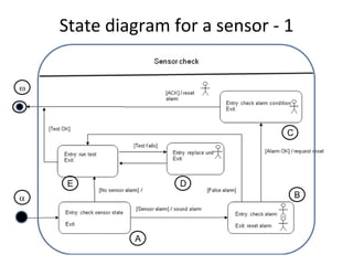
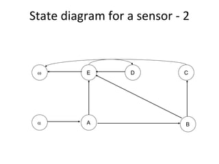
![Sensor round‐trip path tree
A
[no sensor alarm] / test [sensor alarm] / sound alarm
E B
[false alarm] / test [alarm OK / request reset]
[test fails] / replace
[test OK]
E
C
D
[test fails] / replace [ACK] / reset
/ test [test OK]
D
E
/ test
E](https://image.slidesharecdn.com/tdt4242-110828132951-phpapp02/85/Tdt4242-267-320.jpg)


![Example
byte[] readFile() throws IOException {
...
final InputStream is = new FileInputStream(…);
...
while((offset < bytes.length) &&
(numRead = is.read(bytes,offset,(bytes.length-offset))) >=0)
offset += numRead;
...
is.close();
return bytes;
}
What could go wrong with this code?
• new FileInputStream() can throw FileNotFoundException
• InputStream.read() can throw IOException and
IndexOutOfBoundsException and can return -1 for end of file
• is.close() can throw IOException](https://image.slidesharecdn.com/tdt4242-110828132951-phpapp02/85/Tdt4242-394-320.jpg)
![Code containing array references
Code segment. The array b has 10 elements
i = x + 3;
IF b[i] <=5 THEN ,,,
ELSE …
We need three predicates:
b[x + 3] <= 5 – the original predicate
• x + 3 >= 1 – not below lower bound
• x + 3 <= 10 – not above upper bound](https://image.slidesharecdn.com/tdt4242-110828132951-phpapp02/85/Tdt4242-437-320.jpg)

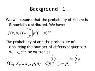
![Model – 1
We will use the following notation:
• c: a coverage measure
• r(c): reliability
• 1 – r(c): failure rate
• r(c) = 1 – k*exp(-b*c)
Thus, we also have that
ln[1 – r(c)] = ln(k) – b*c](https://image.slidesharecdn.com/tdt4242-110828132951-phpapp02/85/Tdt4242-467-320.jpg)
![Model – 2
The equation ln[1 – r(c)] = ln(k) – b*c is of
the same type as Y = α*X + β.
We can thus use linear regression to
estimate the parameters k and b by doing
as follows:
1.Use linear regression to estimate α and β
2.We then have
– k = exp(α)
– b=-β](https://image.slidesharecdn.com/tdt4242-110828132951-phpapp02/85/Tdt4242-468-320.jpg)
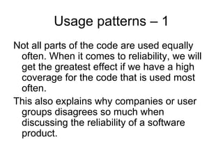
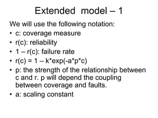
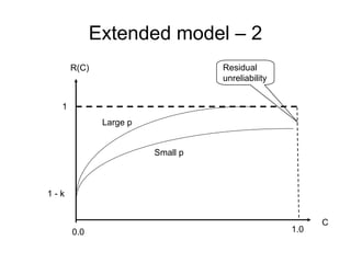
![Extended model - comments
The following relation holds:
ln[1 – r(c)] = ln(k) – a*p*c
• Strong coupling between coverage and
faults will increase the effect of test
coverage on the reliability.
• Weak coupling will create a residual gap
for reliability that cannot be fixed by more
testing, only by increasing the coupling
factor p – thus changing the usage
pattern.](https://image.slidesharecdn.com/tdt4242-110828132951-phpapp02/85/Tdt4242-479-320.jpg)

If we use the expression on the previous
slide to eliminate C(n) we get
N 0 N (n) 1
1
N0 k ( nf ) p 1](https://image.slidesharecdn.com/tdt4242-110828132951-phpapp02/85/Tdt4242-482-320.jpg)

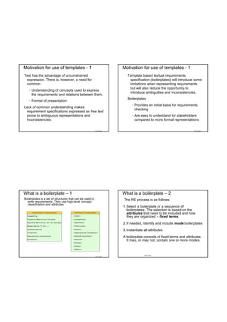
![User Story Cards have 3 parts User Story Template – 1
1. Description ‐ A written description of the user story for planning ‐ As a [user role] I want to [goal]
purposes and as a reminder so I can [reason]
- As a [type of user] I want to [perform some task] so
2. Conversation ‐ A section for capturing further information about the that I can [reach some goal]
user story and details of any conversations
3. Confirmation ‐ A section to convey what tests will be carried out to
confirm the user story is complete and working as expected Example:
• As a registered user I want to log in
so I can access subscriber‐only content
User Story Template – 2 User Story Description
Steps:
• Who (user role) • Start with a title.
• Add a concise description using the templates.
• What (goal) • Add other relevant notes, specifications, or sketches
• Why (reason) • Before building software write acceptance criteria
• gives clarity as to why a feature is useful
(how do we know when we’re done?)
• can influence how a feature should function
• can give you ideas for other useful features
that support the user's goals
Example: Front of Card Example: Back of Card](https://image.slidesharecdn.com/tdt4242-110828132951-phpapp02/85/Tdt4242-504-320.jpg)
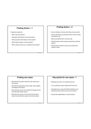
![Use-Case Maps Use-Case Maps – path
Definition: A visual representation of the requirements Start
Point
Path End
Point
of a system, using a precisely defined set of symbols for
responsibilities, system components, and sequences.
… … Responsibility
Links behavior and structure in an explicit and visual
way … … Direction Arrow
UCM paths: Architectural entities that describe causal … … Timestamp Point
relationships between responsibilities, which are bound … …
to underlying organizational structures of abstract Failure Point
components. … …
Shared Responsibility
UCM paths are intended to bridge the gap between UCM Path Elements
requirements (use cases) and detailed design
TDT 4242 TDT 4242
Use Case Maps example - path Use‐Case Maps – AND / OR
Mainly consist of path elements and components
UCM Example: Commuting OR-Fork
& Guarding … …
Conditions
[C1] OR-Join
home transport elevator [C2]
… … … …
secure take [C3]
ready
home
commute
elevator … …
to in
leave X X X
cubicle … …
home AND-Fork AND-Join
… … … …
… …
Basic Path Responsibility Point Component UCM Forks and Joins
(from circle to bar) (generic)
TDT 4242](https://image.slidesharecdn.com/tdt4242-110828132951-phpapp02/85/Tdt4242-517-320.jpg)
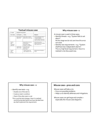
![Use Case Map Use Case Maps – example 1
Dynamic Structures
Contains pre‐conditions
Generic UCM Example or triggering causes
slot A Slot bars
representing
create create (component)
start post‐conditions
+
+ or
path traces through a system resulting effects
pool A move out of objects to explain a causal
slot B sequence, leaving behind a
+ visual signature.
move into move into
copy Pool Example of Use Case map • causal chains of responsibilities
- (component) (crosses, representing actions,
tasks, or functions to be
destroy pool B performed)
- • Responsibilities are normally
• A component is responsible to perform the action, task, or
bound to component when the
end function represented by the responsibility.
destroy cross is inside the component
• Start points may have preconditions attached, while
Dynamic Responsibilities and Dynamic Components responsibilities and end points can have post-conditions.
TDT 4242
Use Case Maps – example
The influence of chosen elements User
[not requested]
[moving]
moving
The elements we choose to include in our door close
motor up
model will decide the use case map but will below
decide on
direction motor down
above
not necessarily influence the actions needed. [stationary]
[requested]
The following examples are meant to in
elevator
add to list
motor
no requests stop
illustrate this. door
[more requests] open
Two elements are always needed: [else]
door
closing-delay
remove
at requested from list
User – requesting service floor
Arrival sensor – indicates when the elevator The elevator control system case study is adapted from Hassan
Arrival Sensor
Gomaa's Designing Concurrent, Distributed, And Real-Time
arrives at the chosen floor. Applications with UML (p459-462), copyright Hassan Gomaa 2001,
published by Addison Wesley. Used with permission.
approaching
floor
Select Destination](https://image.slidesharecdn.com/tdt4242-110828132951-phpapp02/85/Tdt4242-519-320.jpg)
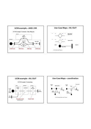
![Model 1 – scheduler Model 1 – Use Case Map
User Scheduler
User Scheduler Arrival Sensor down [requested] Arrival Sensor
up [not requested]
[not requested] [requested] moving approaching
approaching select floor
down floor
up at floor elevator
select moving
at floor elevator below already Elevator
Elevator above add to on list
list decide on door
direction close
below in [on list]
above elevator
add to [else]
list stationary-
in at requested memory motor
elevator floor up
motor
door down
closing-delay
at requested remove from list
floor remove from list
motor Service Personnel
switch on motor
stop stop
door open Arch. Alternative (I) door open
Model 2 – scheduler and status & plan Model 2 – Use Case Map
User
User Scheduler Status & Plan
Status & Plan down
up Scheduler [not requested] [requested]
select [not requested] [requested] Arrival Sensor
down elevator select Arrival Sensor
up elevator Elev. Control
at floor
already approaching
Elev. Mgr Elev. Control on list moving floor
at floor below Elev. Mgr
above [on list]
Elevator
decide on Elevator
in direction
below [else] door
elevator close
above Status & Plan Status & Plan
stationary-
add to memory
in list
elevator add to at requested
door motor
list floor
closing- up
motor
delay down
remove
from list
at requested remove
floor from list motor Service Personnel
stop switch on
motor
stop
Service Personnel
switch on door open Arch. Alternative (II) door open](https://image.slidesharecdn.com/tdt4242-110828132951-phpapp02/85/Tdt4242-520-320.jpg)
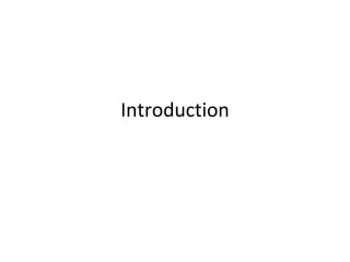
![Requirements
and
Testing
TDT
4242
Exercise
1:
Consider
the
following
goals
in
an
Adaptive
Cruise
Control
system
for
vehicles
stated
below:
a) Identify
the
combination
of
sub-‐goals
that
would
jointly
contribute
to
each
of
the
goals.
b) Build
a
refinement
graph
showing
low-‐level
and
high-‐level
goals,
requirements,
assumptions,
domain
properties
and
associated
agents.
Hint:
Identify
behavioural
goals
and
soft
goals.
Identify
functional
and
non-‐functional
goals.
Goal
acc:
control
basis
Source
[ISO15622]
Description
When ACC is active, vehicle speed shall be controlled automatically either to
• maintain
time
gap
to
a
forward
vehicle,
or
to
• maintain
the
set
speed
whichever speed is lower.
Goal
acc:
System
States
Source
[ISO15622]
Description
The ACC system shall have three system states: ACC off, ACC stand-by and
ACC active, where two different modes are distinguished: ACC speed control
and ACC time gap control. The transitions between the states ACC stand-by
and ACC active are triggered by the driver via the human machine interface.
*Manually and/or automatically after self test. Manual transition describes a
switch to enable/disable ACC function. Automatic switch off can be forced by
failure reaction.](https://image.slidesharecdn.com/tdt4242-110828132951-phpapp02/85/Tdt4242-686-320.jpg)
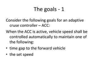
![Goal
acc:
control
preceding
vehicle
Source
[ISO15622]
Description
In case of several preceding vehicles, the preceding vehicle to be followed
shall be selected automatically.
Goal
acc:
functional
types
Source
[ISO15622]
Description
The ACC shall support a range of types:
1. Type
1a:
manual
clutch
operation
2. Type
1b:
no
manual
clutch
operation,
no
active
brake
control
3. Type
2a:
manual
clutch
operation,
active
brake
control
4. Type
2b:
active
brake
control
Notes:
1. To
be
completed
in
week
4
2. Need
to
understand
ISO
15622
–
Transport
information
and
control
systems:
Adaptive
Cruise
Control
Systems
–
performance
requirements
and
test
procedures.](https://image.slidesharecdn.com/tdt4242-110828132951-phpapp02/85/Tdt4242-687-320.jpg)


![Side 2 av 11
Introduction
In this exam you can score a maximum of 70 points. The rest of the total possible score of 100
points for the semester comes from the compulsory exercises.
If you feel that any of the problems require information that you do not find in the text, then
you should
• Document the necessary assumptions
• Explain why you need them
Your answers should be brief and to the point.
Problem 1 – Requirements engineering (20 points)
Toga Islands airspace is divided into four zones (centres), and each zone is divided into
sectors. Also within each zone are portions of airspace, about 50 miles (80.5 km) in diameter,
called TRACON (Terminal Radar Approach CONtrol) airspaces. Within each TRACON
airspace there is a number of airports, each of which has its own airspace with a 5-mile (8-
km) radius.
For jet powered airliners flying within Toga airspace, the cruising altitudes typically vary
between approximately 25,000 feet and 40,000 feet. All other engines are only allowed to fly
at a cruising altitude below 25,000 feet. Allowable cruising altitude is dependent on the speed
of the aircraft.
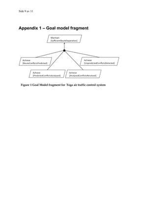
Consider the goal model fragment of an air traffic control system for Toga Islands in the
diagram in appendix 1. The parent goal roughly states that aircraft routes should be
sufficiently separated. The refinement is intended to produce sub-goals for continually
separating routes based on different kinds of conflicts that can rise among routes. The goal
Achieve[RouteConflictsPredicted] roughly states that the air traffic control system should be
able to predict route conflicts associated with aircraft flying within Toga airspace.
1a –– 15 points
1. Identify the parent goal of the goal Maintain[SufficientRouteSeparation].
Maintain[SafeFlight] is considered to be the right answer. With logical reasons, marks
should also be given for answers such as: Achive[RouteOptimisation]
Maintain[RouteEfficiency]
2. Based on the description provided above, identify two refinement nodes from the sub-goal
Achieve[RouteConflictsPredicted].
Ideally it is expected that students will use the parameters in the description above (zone,
sector, airport_airspace, cruising_altitute, type_of_engine, speed_of_aircraft) to derive
subgoal, concrete requirement, design constraint or an expectation. Example:
• Maintain[WorstCaseConflictDistance] (sub-goal)
• Achieve[CompareSpeedofAircraft if same zone and same cruising_altitude] (concrete
requirement)
• Achieve[CompareEngineType if same sector and cruising_altitude] (concrete
requirement)](https://image.slidesharecdn.com/tdt4242-110828132951-phpapp02/85/Tdt4242-699-320.jpg)
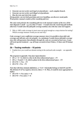
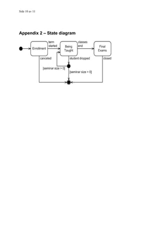
![Side 6 av 11
α
A
cancelled
term started
ω B
class ended
student dropped
[size > 0]
B C
closed
student dropped
[size = 0]
ω ω
ID Start state Event Condition Result New state
1 α Constructor - - Α
2 A Cancelled - - ω
3 A Term started - - B
4 B Student dropped Size = 0 - ω
5 D Student dropped Size > 0 - B
Note that the table is just an example – it is not complete.
Problem 3 – Testing management (30 points)
Our company has a large amount of expertise on testing. Thus, testing other companies’
products has become a major source of income for us. Our testers are especially good at using
all types of assertions during testing.
A large company that specializes in development of software for industrial automation has put
a large test job out for tender. The code will be developed in Java. The test job contains the
following activities:
• Testing of all classes before integration. Unit testing of individual methods has already
been done
• Integrating and testing the subsystems
• Testing the total system, consisting of all the subsystems integrated.
• Construct the first version and necessary infrastructure for a regression test.](https://image.slidesharecdn.com/tdt4242-110828132951-phpapp02/85/Tdt4242-703-320.jpg)

The document discusses using guided natural language and requirement boilerplates to elicit requirements in a semi-formal way that allows both humans and machines to build on their strengths, with guided natural language using defined terms to structure free text requirements and boilerplates providing a structured template to capture requirements in a consistent format. This hybrid approach aims to automate requirements elicitation and analysis as much as possible while still allowing for natural language to incorporate the human strengths in conceptualizing and communicating requirements.