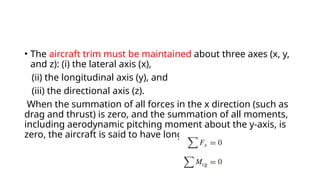
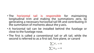
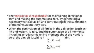
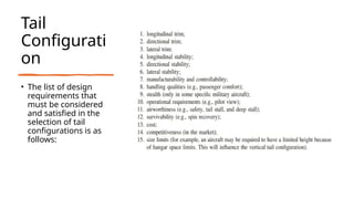
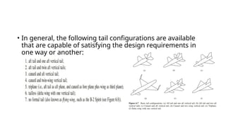
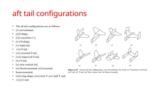
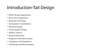
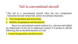
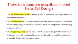
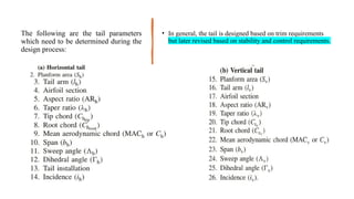
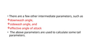
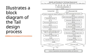
The document outlines the essential aspects of tail design in aircraft, detailing functions and configurations for horizontal and vertical tails, including stability, control, and trim requirements. It describes the iterative design process covering tail parameters, configurations, and practical steps necessary for effective tail implementation. The majority of aircraft use an aft tail configuration, with various designs for optimizing stability and control in flight operations.
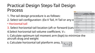
![Tail volume
coefficients
of several
aircraft [5]](https://image.slidesharecdn.com/taildesign-240917053503-ae75d000/85/TAIL-DESIGN-AND-ITS-CONFIGURATION-TYPES-8-320.jpg)