Downloaded 129 times

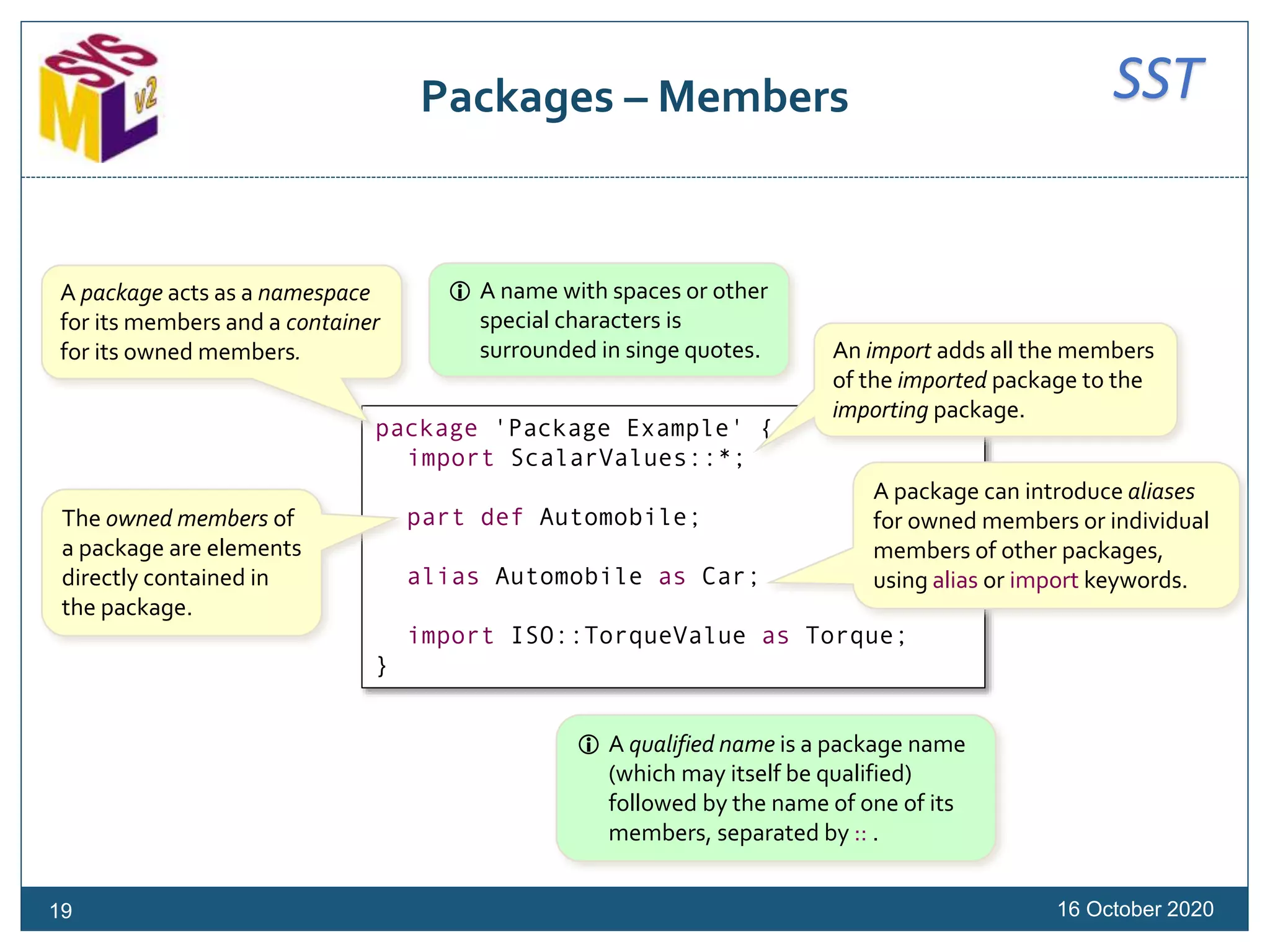
![SSTSubsetting
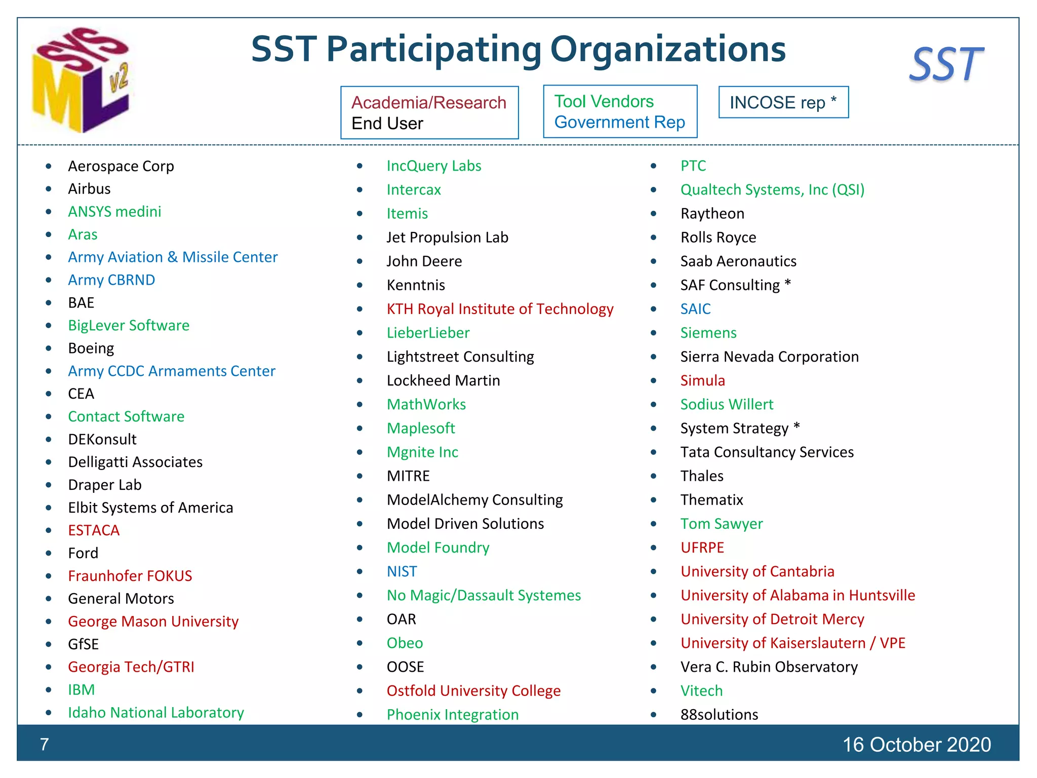
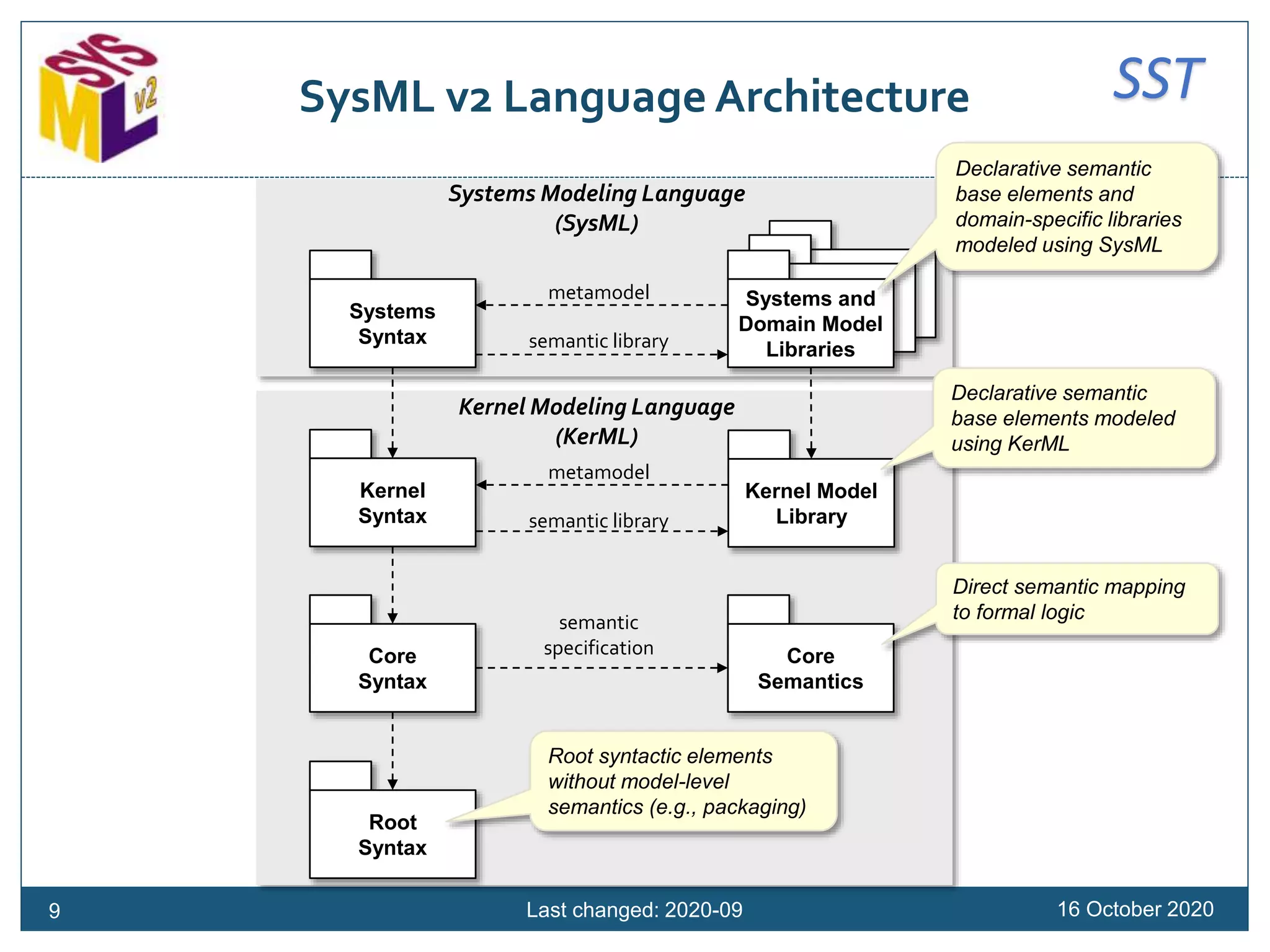
16 October 2020
part def Vehicle {
part parts : VehiclePart[*];
part eng : Engine subsets parts;
part trans : Transmission subsets parts;
part wheels : Wheel[4] :> parts;
}
abstract part def VehiclePart;
part def Engine :> VehiclePart;
part def Transmission :> VehiclePart;
part def Wheel :> VehiclePart;
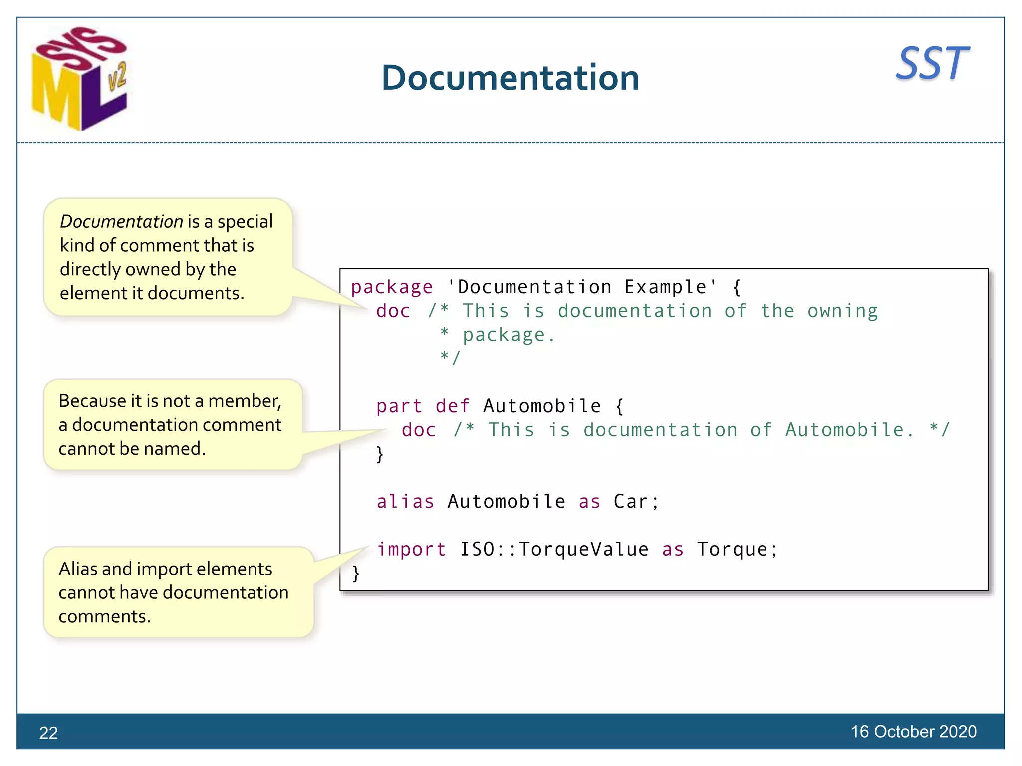
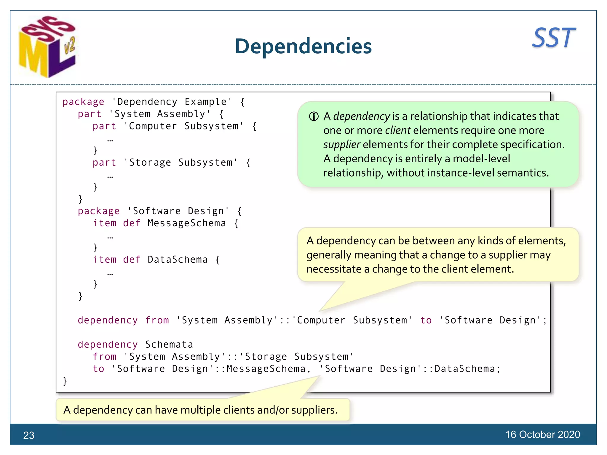
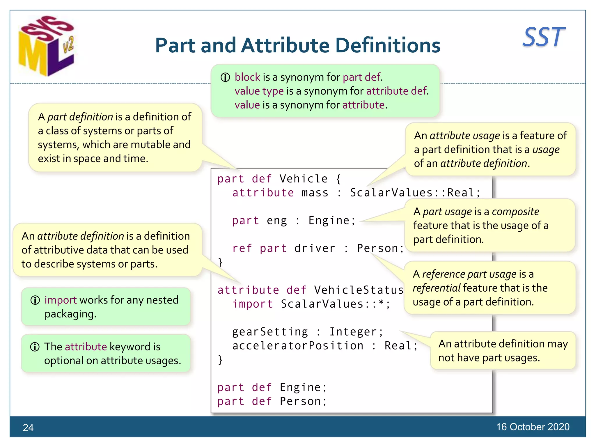
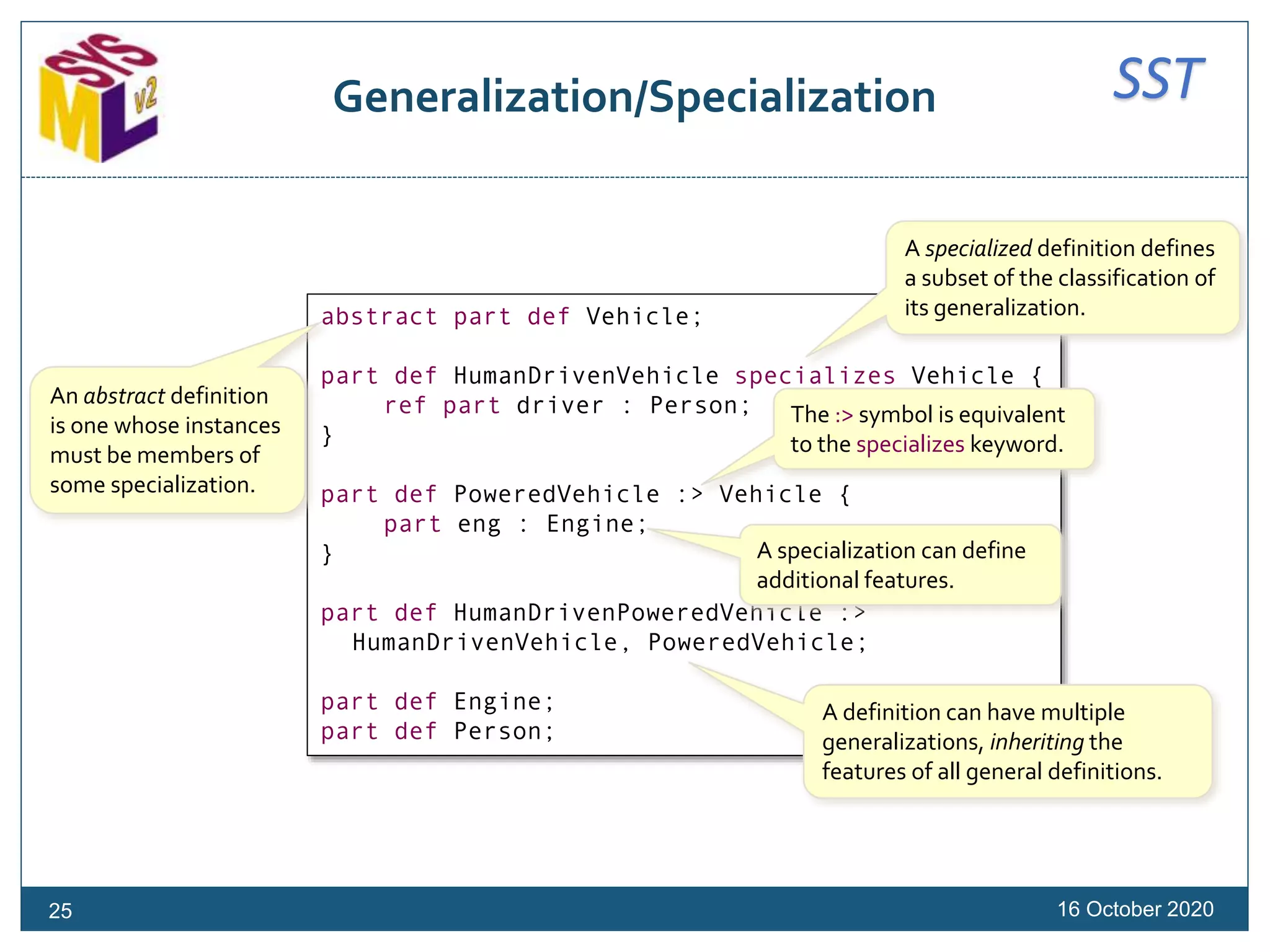
Subsetting asserts that, in any
common context, the values of one
feature are a subset of the values of
another feature.
Subsetting is a kind of
generalization between features.
26](https://image.slidesharecdn.com/sysmlv2201016models-sysmlv2tutorial-201017220950/75/Introduction-to-the-OMG-Systems-Modeling-Language-SysML-Version-2-26-2048.jpg)
![SSTRedefinition
16 October 2020
part def Vehicle {
part eng : Engine;
}
part def SmallVehicle :> Vehicle {
part smallEng : SmallEngine redefines eng;
}
part def BigVehicle :> Vehicle {
part bigEng : BigEngine :>> eng;
}
part def Engine {
part cyl : Cylinder[4..6];
}
part def SmallEngine :> Engine {
part redefines cyl[4];
}
part def BigEngine :> Engine {
part redefines cyl[6];
}
part def Cylinder;
A specialized definition can
redefine a feature that would
otherwise be inherited, to change
its name and/or specialize its type.
The :>> symbol is equivalent
to the redefines keyword.
A feature can also specify
multiplicity.
Redefinition can be used to constrain
the multiplicity of a feature.
There is shorthand notation
for redefining a feature with
the same name.
27](https://image.slidesharecdn.com/sysmlv2201016models-sysmlv2tutorial-201017220950/75/Introduction-to-the-OMG-Systems-Modeling-Language-SysML-Version-2-27-2048.jpg)
![SSTParts (1)
16 October 2020
// Definitions
part def Vehicle {
part eng : Engine;
}
part def Engine {
part cyl : Cylinder[4..6];
}
part def Cylinder;
// Usages
part smallVehicle : Vehicle {
part redefines eng {
part redefines cyl[4];
}
}
part bigVehicle : Vehicle {
part redefines eng {
part redefines cyl[6];
}
}
Typing is a kind of generalization.
Parts inherit properties from
their definitions and can
redefine them, to any level of
nesting.
Parts can be specified
outside the context of a
specific part definition.
28](https://image.slidesharecdn.com/sysmlv2201016models-sysmlv2tutorial-201017220950/75/Introduction-to-the-OMG-Systems-Modeling-Language-SysML-Version-2-28-2048.jpg)
![SSTParts (2)
16 October 2020
// Definitions
part def Vehicle;
part def Engine;
part def Cylinder;
// Usages
part vehicle : Vehicle {
part eng : Engine {
part cyl : Cylinder[4..6];
}
}
part smallVehicle :> vehicle {
part redefines eng {
part redefines cyl[4];
}
}
part bigVehicle :> vehicle {
part redefines eng {
part redefines cyl[6];
}
}
Composite structure can be
specified entirely on parts.
A part can specialize
another part.
29](https://image.slidesharecdn.com/sysmlv2201016models-sysmlv2tutorial-201017220950/75/Introduction-to-the-OMG-Systems-Modeling-Language-SysML-Version-2-29-2048.jpg)
![SSTVariation Definitions
16 October 202031
attribute def Diameter :> LengthValue;
part def Cylinder {
attribute diameter : Diameter[1];
}
part def Engine {
part cylinder : Cylinder[2..*];
}
part '4cylEngine' : Engine {
part redefines cylinder[4];
}
part '6cylEngine' : Engine {
part redefines cylinder[6];
}
// Variability model
variation attribute def DiameterChoices :> Diameter {
variant attribute diameterSmall = 70@[mm];
variant attribute diameterLarge = 100@[mm];
}
variation part def EngineChoices :> Engine {
variant '4cylEngine';
variant '6cylEngine';
}
Any kind of definition can be
marked as a variation,
expressing variability within a
product line model.
A variation defines one or
more variant usages, which
represent the allowed
choices for that variation.
A variation definition will typically
specialize a definition from a design
model, representing the type of thing
being varied.The variants must then
be valid usages of this type.
Variant definitions can also reference
usages defined elsewhere.](https://image.slidesharecdn.com/sysmlv2201016models-sysmlv2tutorial-201017220950/75/Introduction-to-the-OMG-Systems-Modeling-Language-SysML-Version-2-31-2048.jpg)
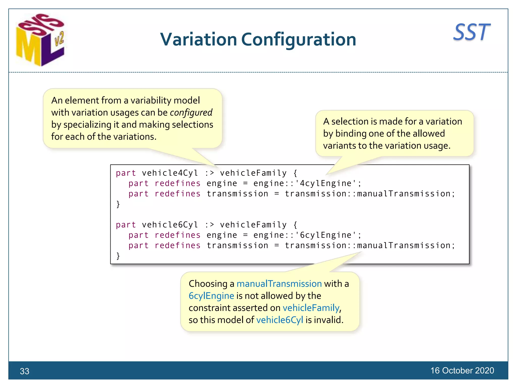
![SSTVariation Usages
16 October 202032
abstract part vehicleFamily : Vehicle {
part engine : EngineChoices[1];
variation part transmission : Transmission[1] {
variant manualTransmission;
variant automaticTransmission;
}
assert constraint {
(engine == engine::'4cylEngine' &
transmission == transmission::manualTransmission) ^
(engine == engine::'6cylEngine' &
transmission == transmission::automaticTransmission)
}
}
A variation definition can be used
like any other definition, but valid
values of the usage are restricted
to the allowed of the variation.Any kind of usage an also be
a variation, defining
allowable variants without a
separate variation definition.
A constraint can be used to
model restrictions across the
choices that can be made.
The operator & means "and" and the operator ^ means "exclusive or".
So, this constraint means "choose either a 4cylEngine and a
manualTransmission, or a 6cylEngine and an automaticTransmission".](https://image.slidesharecdn.com/sysmlv2201016models-sysmlv2tutorial-201017220950/75/Introduction-to-the-OMG-Systems-Modeling-Language-SysML-Version-2-32-2048.jpg)
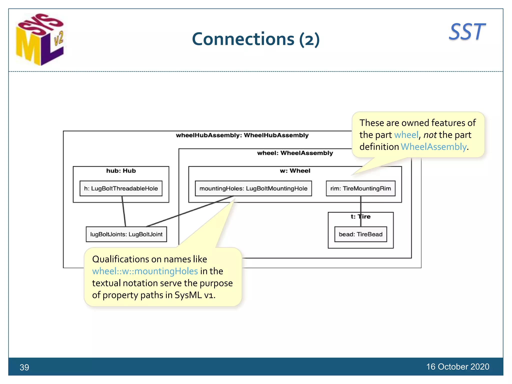
![SSTConnections (1)
16 October 2020
connection def PressureSeat {
end : TireBead[1];
end : TireMountingRim[1];
}
part wheelHubAssembly : WheelHubAssembly {
part wheel : WheelAssembly[1] {
part t : Tire[1] {
part bead : TireBead[2];
}
part w: Wheel[1] {
part rim : TireMountingRim[2];
part mountingHoles : LugBoltMountingHole[5];
}
connection : PressureSeat connect t::bead to w::rim;
}
part lugBoltJoints : LugBoltJoint[0..5];
part hub : Hub[1] {
part h : LugBoltThreadableHole[5];
}
connect lugBoltJoints[0..1]
to mountingHole => wheel::w::mountingHoles[1];
connect lugBoltJoints[0..1]
to threadedHole => hub::h[1];
}
A connection definition is a part
definition whose usages are
connections between its ends.
Connection ends are
reference usages by default
(use part for composition).
A connection is a usage of
an association block that
links to other properties.
If a connection definition
is not specified, a generic
Connection type is used.
38
assoc block is a synonym
for connection def.
link is a synonym for
connection.](https://image.slidesharecdn.com/sysmlv2201016models-sysmlv2tutorial-201017220950/75/Introduction-to-the-OMG-Systems-Modeling-Language-SysML-Version-2-38-2048.jpg)
![SSTInterface Decomposition
16 October 2020
interface def WaterDelivery {
end suppliedBy : SpigotBank[1] {
port hot : Spigot;
port cold : Spigot;
}
end deliveredTo : Faucet[1..*] {
port hot : FaucetInlet;
port cold : FaucetInlet;
}
connect suppliedBy::hot to deliveredTo::hot;
connect suppliedBy::cold to deliveredTo::cold;
}
Connection ends have multiplicities
corresponding to navigating across
the connection…
…but they can be interconnected like
participant features.
44
«interface def»
WaterDelivery
hot hot
cold cold
suppliedBy :
SpigotBank[1]
deliveredTo :
Faucet[1..*]](https://image.slidesharecdn.com/sysmlv2201016models-sysmlv2tutorial-201017220950/75/Introduction-to-the-OMG-Systems-Modeling-Language-SysML-Version-2-44-2048.jpg)
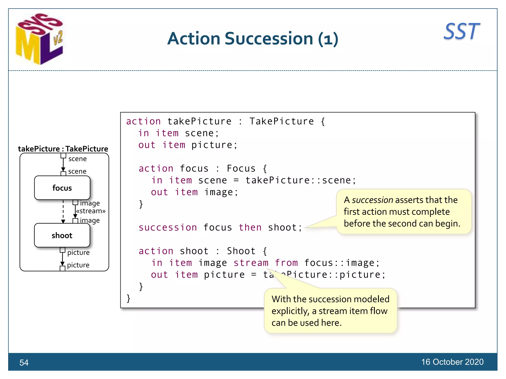
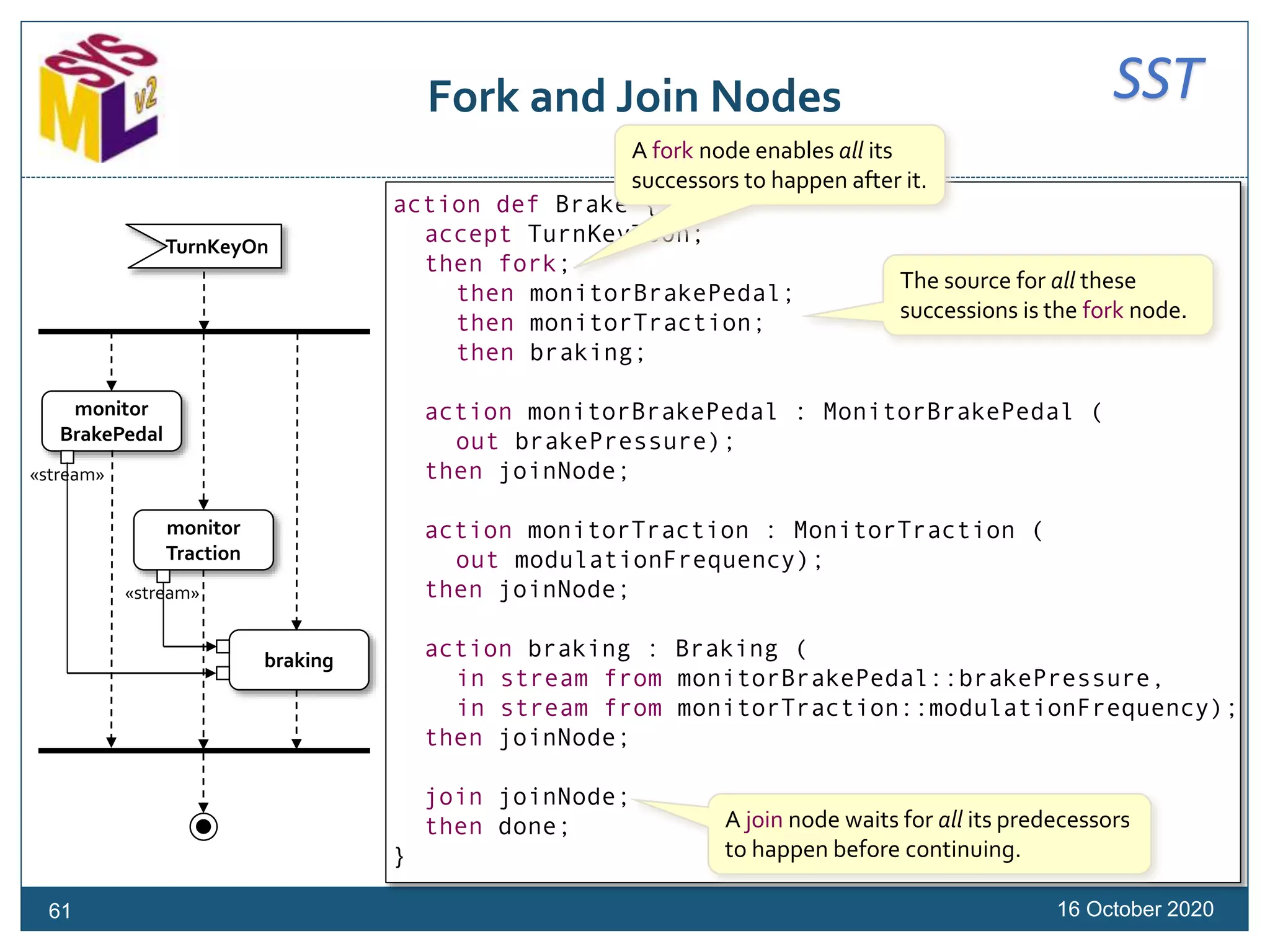
![SSTConditional Succession (1)
16 October 2020
action takePicture : TakePicture {
in item scene;
out item picture;
action focus : Focus {
in item scene = takePicture::scene;
out item image;
}
succession focus
if focus::image::isFocused then shoot;
action shoot : Shoot {
in item image stream from focus::image;
out item picture = takePicture::picture;
}
}
A conditional succession asserts that the
second action must follow the first only
if a guard condition is true. If the guard
is false, succession is not possible.
56
[image::
isFocused]
scene
scene
image
image
picture
picture
focus
shoot
takePicture :TakePicture
«stream»](https://image.slidesharecdn.com/sysmlv2201016models-sysmlv2tutorial-201017220950/75/Introduction-to-the-OMG-Systems-Modeling-Language-SysML-Version-2-56-2048.jpg)
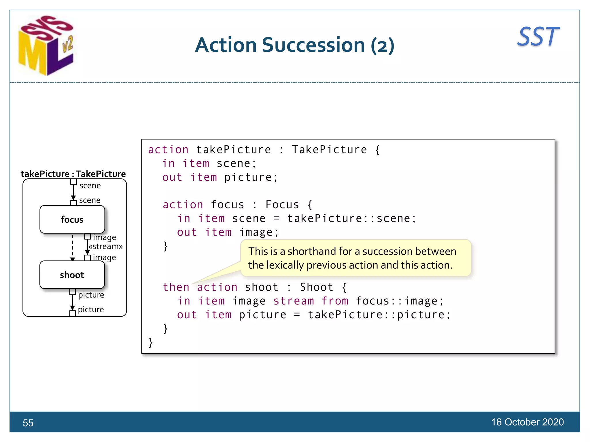
![SSTConditional Succession (2)
16 October 2020
action takePicture : TakePicture {
in item scene;
out item picture;
action focus : Focus {
in item scene = takePicture::scene;
out item image;
}
if focus::image::isFocused then shoot;
action shoot : Shoot {
in item image stream from focus::image;
out item picture = takePicture::picture;
}
}
This is a shorthand for a conditional succession
following the lexically previous action.
57
[image::
isFocused]
scene
scene
image
image
picture
picture
focus
shoot
takePicture :TakePicture
«stream»
Note that, currently,
the target action must
be explicitly named.](https://image.slidesharecdn.com/sysmlv2201016models-sysmlv2tutorial-201017220950/75/Introduction-to-the-OMG-Systems-Modeling-Language-SysML-Version-2-57-2048.jpg)
![SSTDecision Nodes
16 October 2020
action def ChargeBattery {
first start;
then merge continueCharging;
then action monitor
accept batteryCharge : Real;
then decide;
if monitor::batteryCharge < 100 then addCharge;
if monitor::batteryCharge >= 100 then signalCharged;
action addCharge : AddCharge (batteryCharge);
then continueCharging;
send signalCharged
of BatteryCharged()
to powerSystem;
then done;
}
monitor
addCharge
signalCharged
continueCharging
[batteryCharge < 100]
[batteryCharge >= 100]
A decision node is typically followed
by one or more conditional
successions (the last “if…then” can
be replaced by “else”).
The notation “BatteryCharged()” means to
create an instance of the type BatteryCharged to
send as a signal to powerSystem.
References the end of the action
as the target of a succession.
60
A decision node (decide
keyword) chooses exactly one
successor to happen after it.](https://image.slidesharecdn.com/sysmlv2201016models-sysmlv2tutorial-201017220950/75/Introduction-to-the-OMG-Systems-Modeling-Language-SysML-Version-2-60-2048.jpg)
![SSTOpaque Actions
16 October 202062
action def UpdateSensors (in sensors : Sensor[*]) {
language "Alf"
/*
* for (sensor in sensors) {
* if (sensor.ready) {
* Update(sensor);
* }
* }
*/
}
An "opaque" action definition or
usage can be specified using a
textual representation annotation
in a language other than SysML.
The textual representation body is written
using comment syntax.The /*, */ and leading
* symbols are not included in the body text.
Note that support for referencing SysML
elements from the body text is tool-specific.
A textual representation annotation can actually be used with any kind of
element, not just actions. OMG-standard languages a tool may support include
"OCL" (Object Constraint Language) and "Alf" (Action Language for fUML).A tool
can also provide support for other languages (e.g., "JavaScript" or "Modelica").](https://image.slidesharecdn.com/sysmlv2201016models-sysmlv2tutorial-201017220950/75/Introduction-to-the-OMG-Systems-Modeling-Language-SysML-Version-2-62-2048.jpg)
![SSTAction Allocation
16 October 2020
part camera : Camera {
port cameraPort {
in item scene = takePhoto::scene;
out item picture = takePhoto::picture;
}
perform action takePhoto[*] ordered
:> takePicture (in scene, out picture);
part f : AutoFocus {
perform takePhoto::focus;
}
part i : Imager {
perform takePhoto::shoot;
}
}
63
perform identifies the
owner as the performer
of an action.
This shorthand simply
identifies the performed
action owned elsewhere
without renaming it locally.
Flow features in ports
can be bound to action
parameters.](https://image.slidesharecdn.com/sysmlv2201016models-sysmlv2tutorial-201017220950/75/Introduction-to-the-OMG-Systems-Modeling-Language-SysML-Version-2-63-2048.jpg)
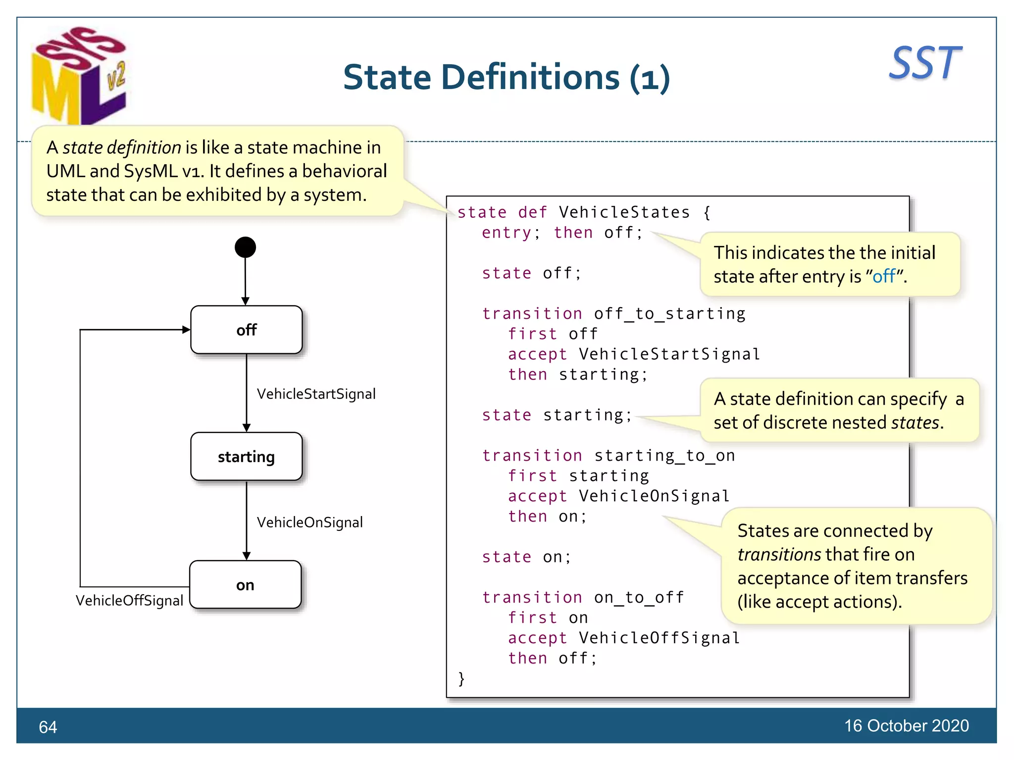
![SSTTransition Guards and Effect Actions
16 October 202069
action performSelfTest(vehicle : Vehicle);
state def VehicleStates(operatingVehicle : Vehicle);
state vehicleStates : VehicleStates (
operatingVehicle : Vehicle,
controller : VehicleController) {
entry; then off;
state off;
accept VehicleStartSignal
then starting;
state starting;
accept VehicleOnSignal
if operatingVehicle::brakePedalDepressed
do send ControllerStartSignal() to controller
then on;
state on { … }
accept VehicleOffSignal
then off;
}
off
starting
on
VehicleOnSignal
VehicleStartSignal
[brakePedalDepressed]/
send ControllerStartSignal()
VehicleOffSignal
vehicleStates :VehicleStates
A guard is a condition
that must be true for a
transition to fire.
An effect action is performed
when a transition fires, before
entry to the target state.](https://image.slidesharecdn.com/sysmlv2201016models-sysmlv2tutorial-201017220950/75/Introduction-to-the-OMG-Systems-Modeling-Language-SysML-Version-2-69-2048.jpg)
![SSTExpressions
Mass Rollup Example (1)
16 October 2020
package MassRollup {
import ScalarFunctions::*;
part def MassedThing {
attribute mass subsets ISQ::mass;
attribute totalMass subsets ISQ::mass;
}
part simpleThing : MassedThing {
attribute redefines totalMass = mass;
}
part compositeThing : MassedThing {
part subcomponents: MassedThing[*];
attribute redefines totalMass =
mass + sum(subcomponents->collect p:MassedThing (p::totalMass));
}
}
From the International
System of Quantities
library model.
Alf-based expression
language.
71
Eventually, the shorthand notation
subcomponents.totalMass will be usable
instead of explicit collect (like in OCL).](https://image.slidesharecdn.com/sysmlv2201016models-sysmlv2tutorial-201017220950/75/Introduction-to-the-OMG-Systems-Modeling-Language-SysML-Version-2-71-2048.jpg)
![SSTExpressions
Mass Rollup Example (2)
16 October 2020
import ScalarValues::*;
import MassRollup::*;
part def CarPart :> MassedThing {
attribute serialNumber : String;
}
part car: CarPart :> compositeThing {
attribute vin redefines serialNumber;
part carParts : CarPart[*] redefines subcomponents;
part engine :> simpleThing subsets carParts { … }
part transmission :> simpleThing subsets carParts { … }
}
// Example usage
import SI::*;
part c :> car {
redefines car::mass = 1000@[kg];
part redefines engine {
redefines engine::mass = 100@[kg];
}
part redefines transmission {
redefines transmission::mass = 50@[kg];
}
}
// c.totalMass --> 1150.0@[kg]
Units are identified on
the value, not the type.
72](https://image.slidesharecdn.com/sysmlv2201016models-sysmlv2tutorial-201017220950/75/Introduction-to-the-OMG-Systems-Modeling-Language-SysML-Version-2-72-2048.jpg)
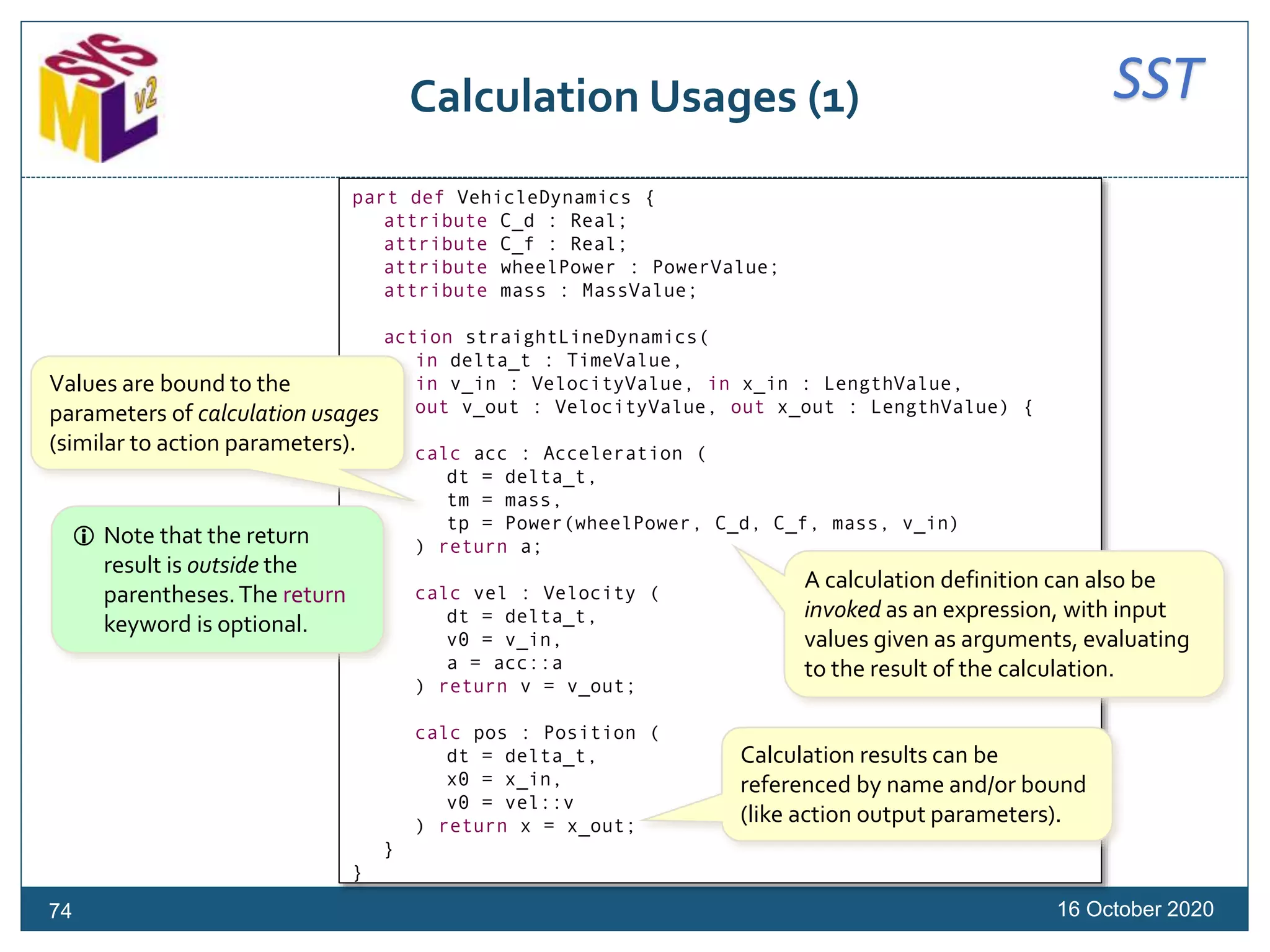
![SSTConstraint Definitions (1)
16 October 202076
import ISQ::*;
import SI::*;
import ScalarFunctions::*;
constraint def MassConstraint (
partMasses : MassValue[0..*],
massLimit : MassValue) {
sum(partMasses) <= massLimit
}
part def Vehicle {
constraint massConstraint : MassConstraint (
partMasses = {chassisMass, engine::mass, transmission::mass},
massLimit = 2500@[kg]);
attribute chassisMass : MassValue;
part engine : Engine {
attribute mass : MassValue;
}
part transmission : Engine {
attribute mass : MassValue;
}
}
A constraint definition is a reusable,
parameterized Boolean expression.
Constraint parameters are similar
to the parameters on actions.
The constraint expression can be
any Boolean expression using
the constraint parameters.
There is no semicolon
at the end of a
constraint expression.
A constraint is the usage
of a constraint definition,
which may be true or
false in a given context.
A constraint may be
violated (false) without
making the model
inconsistent.
Values are bound to
constraint parameters
(similarly to actions).](https://image.slidesharecdn.com/sysmlv2201016models-sysmlv2tutorial-201017220950/75/Introduction-to-the-OMG-Systems-Modeling-Language-SysML-Version-2-76-2048.jpg)
![SSTConstraint Definitions (2)
16 October 202077
import ISQ::*;
import SI::*;
import ScalarFunctions::*;
constraint def MassConstraint {
attribute partMasses : MassValue[0..*];
attribute massLimit : MassValue;
sum(partMasses) <= massLimit
}
part def Vehicle {
constraint massConstraint : MassConstraint {
redefines partMasses = {chassisMass, engine::mass, transmission::mass};
redefines massLimit = 2500@[kg];
}
attribute chassisMass : MassValue;
part engine : Engine {
attribute mass : MassValue;
}
part transmission : Engine {
attribute mass : MassValue;
}
}
Alternatively, constraint
parameters may be modeled as
value or reference properties.
The constraint parameter
properties are then redefined
in order to be bound.](https://image.slidesharecdn.com/sysmlv2201016models-sysmlv2tutorial-201017220950/75/Introduction-to-the-OMG-Systems-Modeling-Language-SysML-Version-2-77-2048.jpg)
![SSTConstraint Assertions (1)
16 October 202078
import ISQ::*;
import SI::*;
import ScalarFunctions::*;
constraint def MassConstraint (
partMasses : MassValue[0..*],
massLimit : MassValue) {
sum(partMasses) <= massLimit
}
part def Vehicle {
assert constraint massConstraint : MassConstraint (
partMasses = {chassisMass, engine::mass, transmission::mass},
massLimit = 2500@[kg]);
attribute chassisMass : MassValue;
part engine : Engine {
attribute mass : MassValue;
}
part transmission : Engine {
attribute mass : MassValue;
}
}
A constraint assertion
asserts that a constraint
must be true.
If an assertion is
violated, then the
model is inconsistent.](https://image.slidesharecdn.com/sysmlv2201016models-sysmlv2tutorial-201017220950/75/Introduction-to-the-OMG-Systems-Modeling-Language-SysML-Version-2-78-2048.jpg)
![SSTConstraint Assertions (2)
16 October 202079
constraint def MassConstraint (
partMasses : MassValue[0..*],
massLimit : MassValue);
constraint massConstraint : MassConstraint (
partMasses : MassValue[0..*],
massLimit : MassValue) {
sum(partMasses) <= massLimit
}
part def Vehicle {
assert massConstraint (
partMasses = {chassisMass, engine::mass, transmission::mass},
massLimit = 2500@[kg]);
attribute chassisMass : MassValue;
attribute engine : Engine {
value mass : MassValue;
}
attribute transmission : Engine {
value mass : MassValue;
}
}
The constraint expression
can also be defined on a
usage of a constraint def.
A named constraint
can be asserted in
multiple contexts.](https://image.slidesharecdn.com/sysmlv2201016models-sysmlv2tutorial-201017220950/75/Introduction-to-the-OMG-Systems-Modeling-Language-SysML-Version-2-79-2048.jpg)
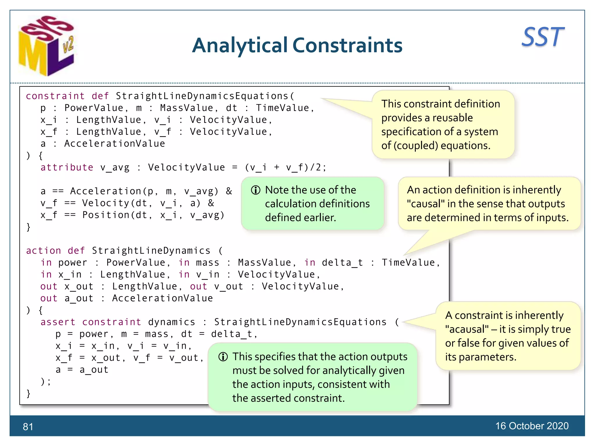
![SSTDerivation Constraints
16 October 202080
part vehicle1 : Vehicle {
attribute totalMass : MassValue;
assert constraint {totalMass == chassisMass + engine::mass + transmission::mass}
}
part vehicle2 : Vehicle {
attribute totalMass : MassValue = chassisMass + engine::mass + transmission::mass;
}
constraint def AveragedDynamics (
mass: MassValue,
initialSpeed : SpeedValue,
finalSpeed : SpeedValue,
deltaT : TimeValue,
force : ForceValue ) {
force * deltaT == mass * (finalSpeed - initialSpeed) &
mass > 0@[kg]
}
In UML and SysML v1, constraints are
often used to defined derived values.
In SysML v2 this can usually be
done more directly using a binding.
However, constraints
allow for more general
equalities and inequalities
than direct derivation.
Be careful about the
difference between ==,
which is the Boolean-valued
equality operator, and =,
which denotes binding.](https://image.slidesharecdn.com/sysmlv2201016models-sysmlv2tutorial-201017220950/75/Introduction-to-the-OMG-Systems-Modeling-Language-SysML-Version-2-80-2048.jpg)
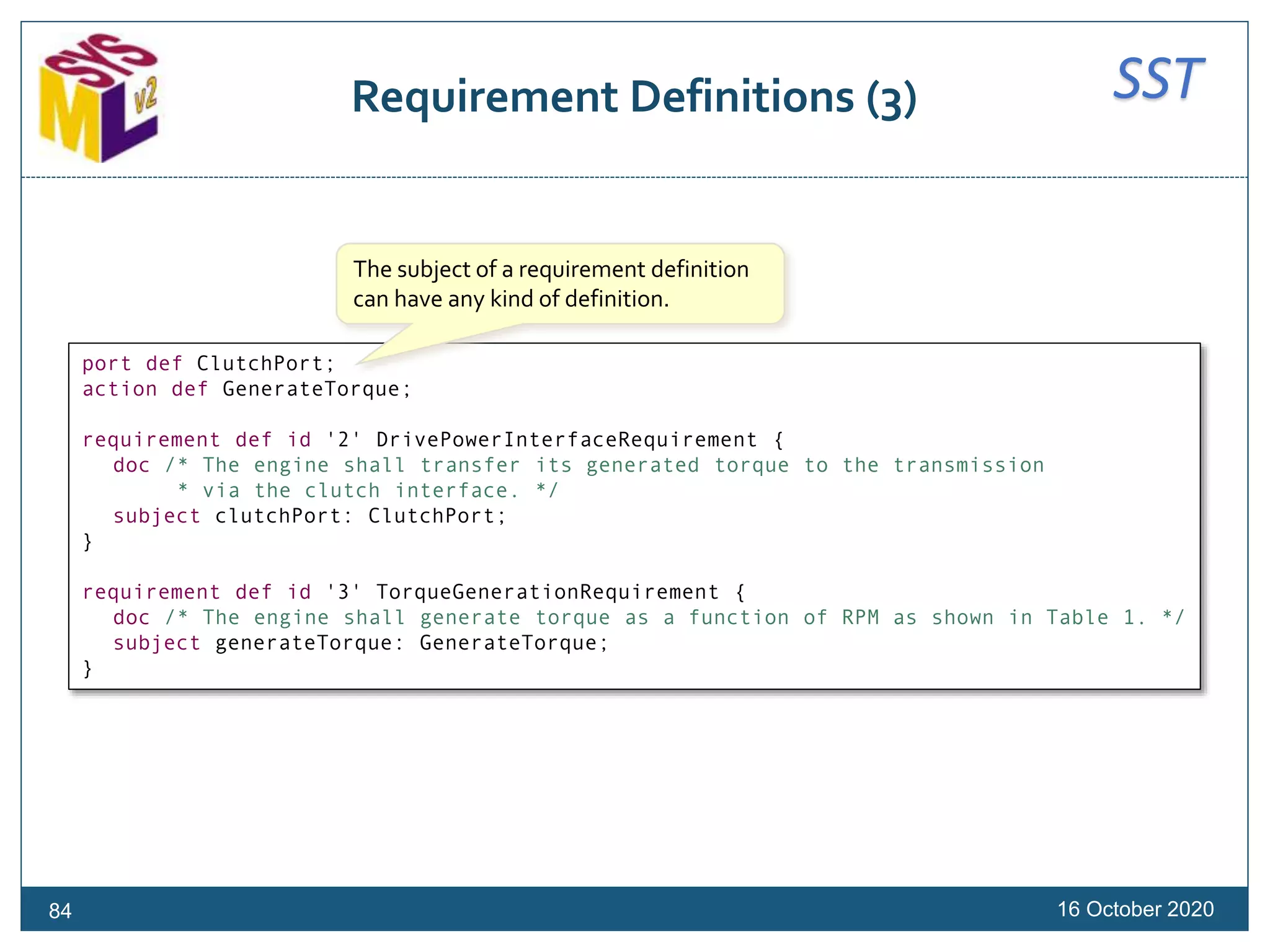
![SSTRequirement Definitions (2)
16 October 202083
part def Vehicle {
attribute dryMass: MassValue;
attribute fuelMass: MassValue;
attribute fuelFullMass: MassValue;
…
}
requirement def id '1' VehicleMassLimitationRequirement :> MassLimitationRequirement {
doc /* The total mass of a vehicle shall be less than or equal to the required mass. */
subject vehicle : Vehicle;
attribute redefines massActual = vehicle::dryMass + vehicle::fuelMass;
assume constraint { vehicle::fuelMass > 0@[kg] }
}
Features of the subject
can be used in the
requirement definition.
A requirement definition is always about some
subject, which may be implicit or specified explicitly.
A requirement definition may also
specify one or more assumptions.
A requirement definition may have a
modeler specified human id, which is
an alternate name for it.](https://image.slidesharecdn.com/sysmlv2201016models-sysmlv2tutorial-201017220950/75/Introduction-to-the-OMG-Systems-Modeling-Language-SysML-Version-2-83-2048.jpg)
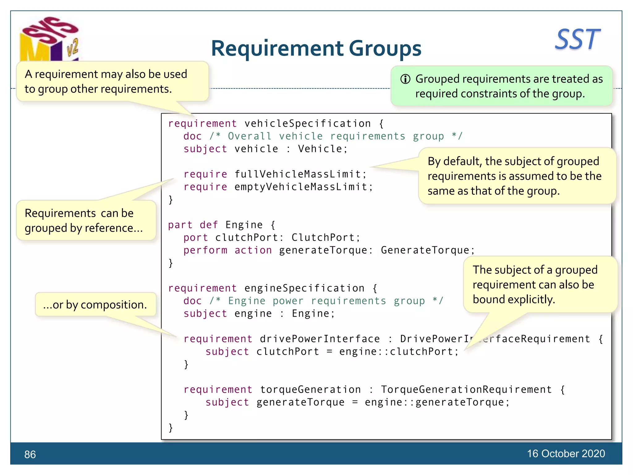
![SSTRequirement Usages
16 October 202085
requirement id '1.1' fullVehicleMassLimit : VehicleMassLimitationRequirement {
subject vehicle : Vehicle;
attribute :>> massReqd = 2000@[kg];
assume constraint {
doc /* Fuel tank is full. */
vehicle::fuelMass == vehicle::fuelFullMass
}
}
requirement id '1.2' emptyVehicleMassLimit : VehicleMassLimitationRequirement {
subject vehicle : Vehicle;
attribute :>> massReqd = 1500@[kg];
assume constraint {
doc /* Fuel tank is empty. */
vehicle::fuelMass == 0@[kg]
}
}
A requirement is the usage of a
requirement definition.
A requirement will often bind
requirement definition
parameters to specific values.
A requirement may optionally
have its own human ID.](https://image.slidesharecdn.com/sysmlv2201016models-sysmlv2tutorial-201017220950/75/Introduction-to-the-OMG-Systems-Modeling-Language-SysML-Version-2-85-2048.jpg)
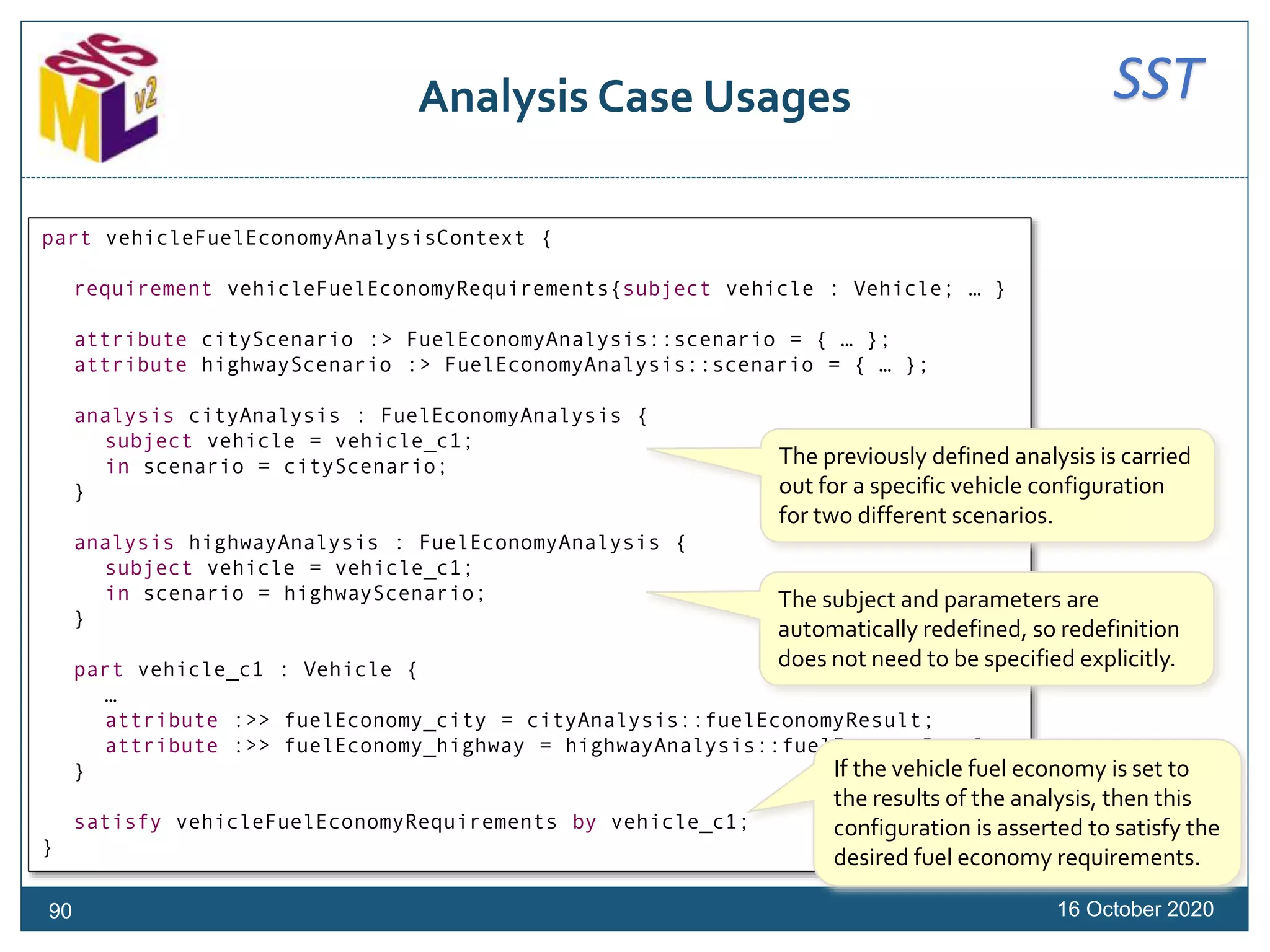
![SSTAnalysis Case Definitions (1)
16 October 202088
analysis def FuelEconomyAnalysis {
subject vehicle : Vehicle;
return fuelEconomyResult : DistancePerVolumeValue;
objective fuelEconomyAnalysisObjective {
doc /*
* The objective of this analysis is to determine whether the
* subject vehicle can satisfy the fuel economy requirement.
*/
assume constraint {
vehicle::wheelDiameter == 33@['in'] &
vehicle::driveTrainEfficiency == 0.4
}
require constraint {
fuelEconomyResult > 30@[mi / gallon]
}
}
…
}
An analysis case definition defines the
computation of the result of analyzing
some subject, meeting an objective.
The subject may be specified similarly to
the subject of a requirement definition).
The analysis result is declared as a return
result (as for a calculation definition).
The analysis objective is specified as a
requirement, allowing both assumed
and required constraints.
The objective is a requirement on
the result of the analysis case.](https://image.slidesharecdn.com/sysmlv2201016models-sysmlv2tutorial-201017220950/75/Introduction-to-the-OMG-Systems-Modeling-Language-SysML-Version-2-88-2048.jpg)
![SSTAnalysis Case Definitions (2)
16 October 202089
analysis def FuelEconomyAnalysis {
subject vehicle : Vehicle;
return fuelEconomyResult : DistancePerVolumeValue;
…
in attribute scenario[*] {
time : TimeValue;
position : LengthValue;
velocity : VelocityValue;
}
action solveForPower {
out power: PowerValue[*];
out acceleration: AccelerationValue[*];
assert constraint {
{1..size(scenario)-1}->forAll i (
StraightLineDynamicsEquations (
power[i], vehicle::mass,
scenario::time[i+1] - scenario::time[i],
scenario::position[i], scenario::velocity[i],
scenario::position[i+1], scenario::velocity[i+1],
acceleration[i+1]))
}
}
then action solveForFuelEconomy {
in power : PowerValue[*] = solveForPower::power;
out fuelEconomy : DistancePerVolumeValue = fuelEconomyResult;
… }
}
The steps of an analysis case
are actions that, together,
compute the analysis result. The first step solves for the
engine power needed for a
given position/velocity scenario.
The second step computes the fuel
economy result, given the power
profile determined in the first step.
Additional parameters can be
specified in the case body.](https://image.slidesharecdn.com/sysmlv2201016models-sysmlv2tutorial-201017220950/75/Introduction-to-the-OMG-Systems-Modeling-Language-SysML-Version-2-89-2048.jpg)
![SSTKernel
Base Functions
16 October 2020
package BaseFunctions {
import Base::*;
import ScalarValues::*;
function '=='(x: Anything, y: Anything): Boolean;
function '!='(x: Anything, y: Anything): Boolean;
function ToString(x: Anything): String;
function size(seq: Anything[*]): Natural;
function isEmpty(seq: Anything[*]): Boolean;
function notEmpty(seq: Anything[0..*]): Boolean;
function head(seq: Anything[0..*]): Boolean;
function tail(seq: Anything[0..*]): Boolean;
function last(seq: Anything[0..*]): Boolean;
…
}
94](https://image.slidesharecdn.com/sysmlv2201016models-sysmlv2tutorial-201017220950/75/Introduction-to-the-OMG-Systems-Modeling-Language-SysML-Version-2-94-2048.jpg)
![SSTKernel
Scalar Functions
16 October 2020
package ScalarFunctions {
import ScalarValues::*;
abstract function '+'(x: ScalarValue, y: ScalarValue[0..1]): ScalarValue;
abstract function '-'(x: ScalarValue, y: ScalarValue[0..1]): ScalarValue;
abstract function '*'(x: ScalarValue, y: ScalarValue): ScalarValue;
abstract function '/'(x: ScalarValue, y: ScalarValue): ScalarValue;
abstract function '**'(x: ScalarValue, y: ScalarValue): ScalarValue;
abstract function '%'(x: ScalarValue, y: ScalarValue): ScalarValue;
abstract function '!'(x: ScalarValue): ScalarValue;
abstract function '~'(x: ScalarValue): ScalarValue;
abstract function '|'(x: ScalarValue, y: ScalarValue): ScalarValue;
abstract function '^'(x: ScalarValue, y: ScalarValue): ScalarValue;
abstract function '&'(x: ScalarValue, y: ScalarValue): ScalarValue;
abstract function '<'(x: ScalarValue, y: ScalarValue): Boolean;
abstract function '>'(x: ScalarValue, y: ScalarValue): Boolean;
abstract function '<='(x: ScalarValue, y: ScalarValue): Boolean;
abstract function '>='(x: ScalarValue, y: ScalarValue): Boolean;
abstract function Max(x: ScalarValue, y: ScalarValue): ScalarValue;
abstract function Min(x: ScalarValue, y: ScalarValue): ScalarValue;
abstract function '@'(x: ScalarValue, y: Base::Anything): ScalarValue;
abstract function '..'(lower: ScalarValue, upper: ScalarValue):ScalarValue[0..*];
abstract function sum(collection: ScalarValue[0..*]): ScalarValue;
abstract function product(collection: ScalarValue[0..*]);
}
95](https://image.slidesharecdn.com/sysmlv2201016models-sysmlv2tutorial-201017220950/75/Introduction-to-the-OMG-Systems-Modeling-Language-SysML-Version-2-95-2048.jpg)
![SSTKernel
Integer Functions
16 October 202098
package IntegerFunctions {
import ScalarValues::*;
function Abs specializes NumericalFunctions::Abs (x: Integer): Natural;
function '+' specializes NumericalFunctions::'+' (x: Integer, y: Integer[0..1]): Integer;
function '-' specializes NumericalFunctions::'-' (x: Integer, y: Integer[0..1]): Integer;
function '*' specializes NumericalFunctions::'*' (x: Integer, y: Integer): Integer;
function '/' specializes NumericalFunctions::'/' (x: Integer, y: Integer): Integer;
function '**' specializes NumericalFunctions::'**' (x: Integer, y: Natural): Integer;
function '%' specializes NumericalFunctions::'%' (x: Integer, y: Integer): Integer;
function '<' specializes NumericalFunctions::'<' (x: Integer, y: Integer): Boolean;
function '>' specializes NumericalFunctions::'>' (x: Integer, y: Integer): Boolean;
function '<=' specializes NumericalFunctions::'<=' (x: Integer, y: Integer): Boolean;
function '>=' specializes NumericalFunctions::'>=' (x: Integer, y: Integer): Boolean;
function Max specializes NumericalFunctions::Max (x: Integer, y: Integer): Integer;
function Min specializes NumericalFunctions::Min (x: Integer, y: Integer): Integer;
function '==' specializes BaseFunctions::'==' (x: Integer, y: Integer): Boolean;
function '!=' specializes BaseFunctions::'!=' (x: Integer, y: Integer): Boolean;
function '..' specializes ScalarFunctions::'..' (lower: Integer, upper: Integer): Integer[0..*];
function ToString specializes BaseFunctions::ToString (x: Integer): String;
function ToNatural(x: Integer): Natural;
function ToInteger(x: String): Integer;
function ToRational(x: Integer): Rational;
function ToReal(x: Integer): Real;
function sum specializes ScalarFunctions::sum (collection: Integer[0..*]): Integer;
function product specializes ScalarFunctions::product (collection: Integer[0..*]): Integer;
}](https://image.slidesharecdn.com/sysmlv2201016models-sysmlv2tutorial-201017220950/75/Introduction-to-the-OMG-Systems-Modeling-Language-SysML-Version-2-98-2048.jpg)
![SSTKernel
Natural Functions
16 October 2020100
package NaturalFunctions {
import ScalarValues::*;
function '+' specializes IntegerFunctions::'+' (x: Natural, y: Natural[0..1]): Natural;
function '*' specializes IntegerFunctions::'*' (x: Natural, y: Natural): Natural;
function '/' specializes IntegerFunctions::'/' (x: Natural, y: Natural): Natural;
function '%' specializes IntegerFunctions::'%' (x: Natural, y: Natural): Natural;
function '<' specializes IntegerFunctions::'<', UnlimitedNaturalFunctions::'<'
(x: Natural, y: Natural): Boolean;
function '>' specializes IntegerFunctions::'>', UnlimitedNaturalFunctions::'>'
(x: Natural, y: Natural): Boolean;
function '<=' specializes IntegerFunctions::'<=', UnlimitedNaturalFunctions::'<='
(x: Natural, y: Natural): Boolean;
function '>=' specializes IntegerFunctions::'>=', UnlimitedNaturalFunctions::'>='
(x: Natural, y: Natural): Boolean;
function Max specializes IntegerFunctions::Max, UnlimitedNaturalFunctions::Max
(x: Natural, y: Natural): Natural;
function '==' specializes IntegerFunctions::'==', UnlimitedNaturalFunctions::'='
(x: UnlimitedNatural, y: UnlimitedNatural): Boolean;
function '/=' specializes IntegerFunctions::'!=', UnlimitedNaturalFunctions::'!='
(x: UnlimitedNatural, y: UnlimitedNatural): Boolean;
function ToString specializes IntegerFunctions::ToString,UnlimitedNaturalFunctions::ToString
(x: Natural): String;
function ToNatural(x: String): Natural;
}](https://image.slidesharecdn.com/sysmlv2201016models-sysmlv2tutorial-201017220950/75/Introduction-to-the-OMG-Systems-Modeling-Language-SysML-Version-2-100-2048.jpg)
![SSTKernel
Rational Functions
16 October 2020101
package RationalFunctions {
import ScalarValues::*;
function Rat(numer: Integer, denum: Integer): Rational;
function Numer(rat: Rational): Integer;
function Denom(rat: Rational): Integer;
function Abs specializes NumericalFunctions::Abs (x: Rational): Rational;
function '+' specializes NumericalFunctions::'+' (x: Rational, y: Rational[0..1]): Rational;
function '-' specializes NumericalFunctions::'-' (x: Rational, y: Rational[0..1]): Rational;
function '*' specializes NumericalFunctions::'*' (x: Rational, y: Rational): Rational;
function '/' specializes NumericalFunctions::'/' (x: Rational, y: Rational): Rational;
function '**' specializes NumericalFunctions::'**' (x: Rational, y: Rational): Rational;
function '<' specializes NumericalFunctions::'<' (x: Rational, y: Rational): Boolean;
function '>' specializes NumericalFunctions::'>' (x: Rational, y: Rational): Boolean;
function '<=' specializes NumericalFunctions::'<=' (x: Rational, y: Rational): Boolean;
function '>=' specializes NumericalFunctions::'>=' (x: Rational, y: Rational): Boolean;
function Max specializes NumericalFunctions::Max (x: Rational, y: Rational): Rational;
function Min specializes NumericalFunctions::Min (x: Rational, y: Rational): Rational;
function '==' specializes BaseFunctions::'==' (x: Rational, y: Rational): Boolean;
function '!=' specializes BaseFunctions::'!=' (x: Rational, y: Rational): Boolean;
function GCD(x: Rational, y: Rational): Integer;
function Floor(x: Rational): Integer;
function Round(x: Rational): Integer;
function ToString specializes BaseFunctions::ToString (x: Rational): String;
function ToInteger(x: Rational): Integer;
function ToRational(x: String): Rational;
function ToReal(x: Rational): Real;
function ToComplex(x: Rational): Complex;
function sum specializes ScalarFunctions::sum(collection: Rational[0..*]): Rational;
function product specializes ScalarFunctions::product(collection: Rational[0..*]): Rational;
}](https://image.slidesharecdn.com/sysmlv2201016models-sysmlv2tutorial-201017220950/75/Introduction-to-the-OMG-Systems-Modeling-Language-SysML-Version-2-101-2048.jpg)
![SSTKernel
Real Functions
16 October 2020102
package RealFunctions {
import ScalarValues::*;
function Abs specializes NumericalFunctions::Abs (x: Real): Real;
function '+' specializes NumericalFunctions::'+' (x: Real, y: Real[0..1]): Real;
function '-' specializes NumericalFunctions::'-' (x: Real, y: Real[0..1]): Real;
function '*' specializes NumericalFunctions::'*' (x: Real, y: Real): Real;
function '/' specializes NumericalFunctions::'/' (x: Real, y: Real): Real;
function '**' specializes NumericalFunctions::'**' (x: Real, y: Real): Real;
function '<' specializes NumericalFunctions::'<' (x: Real, y: Real): Boolean;
function '>' specializes NumericalFunctions::'>' (x: Real, y: Real): Boolean;
function '<=' specializes NumericalFunctions::'<=' (x: Real, y: Real): Boolean;
function '>=' specializes NumericalFunctions::'>=' (x: Real, y: Real): Boolean;
function Max specializes NumericalFunctions::Max (x: Real, y: Real): Real;
function Min specializes NumericalFunctions::Min (x: Real, y: Real): Real;
function '==' specializes BaseFunctions::'==' (x: Real, y: Real): Boolean;
function '!=' specializes BaseFunctions::'!=' (x: Real, y: Real): Boolean;
function Sqrt(x: Real): Real;
function Floor(x: Real): Integer;
function Round(x: Real): Integer;
function ToString specializes BaseFunctions::ToString (x: Real): String;
function ToInteger(x: Real): Integer;
function ToRational(x: Real): Rational;
function ToReal(x: String): Real;
function ToComplex(x: Real): Complex;
function sum specializes ScalarFunctions::sum (collection: Real[0..*]): Real;
function product specializes ScalarFunctions::product (collection: Real[0..*]): Real;
}](https://image.slidesharecdn.com/sysmlv2201016models-sysmlv2tutorial-201017220950/75/Introduction-to-the-OMG-Systems-Modeling-Language-SysML-Version-2-102-2048.jpg)
![SSTQuantities and Units
Units
16 October 2020
package UnitsAndScales {
attribute def MeasurementReference {
attribute name : ScalarValues::String;
attribute scaleValueDefinition : ScaleValueDefinition[0..*];
}
abstract attribute def MeasurementUnit :> MeasurementReference {
attribute unitPowerFactor : UnitPowerFactor[1..*] ordered;
attribute unitConversion : UnitConversion[0..1];
}
abstract value type SimpleUnit :> MeasurementUnit {
attribute redefines unitPowerFactor[1] {
attribute redefines unit = SimpleUnit::self;
attribute redefines exponent = 1;
}
}
abstract attribute def DerivedUnit :> MeasurementUnit;
attribute def UnitPowerFactor {
attribute unit : MeasurementUnit;
attribute exponent : ScalarValues::Number;
}
…
}
A measurement unit is a
measurement scale defined as a
sequence of unit power factors.
A simple unit is a measurement
unit with no power factor
dependencies on other units.
A derived unit is any unit that is
not simple.
A unit power factor is a
representation of a unit
raised to an exponent.
104](https://image.slidesharecdn.com/sysmlv2201016models-sysmlv2tutorial-201017220950/75/Introduction-to-the-OMG-Systems-Modeling-Language-SysML-Version-2-104-2048.jpg)

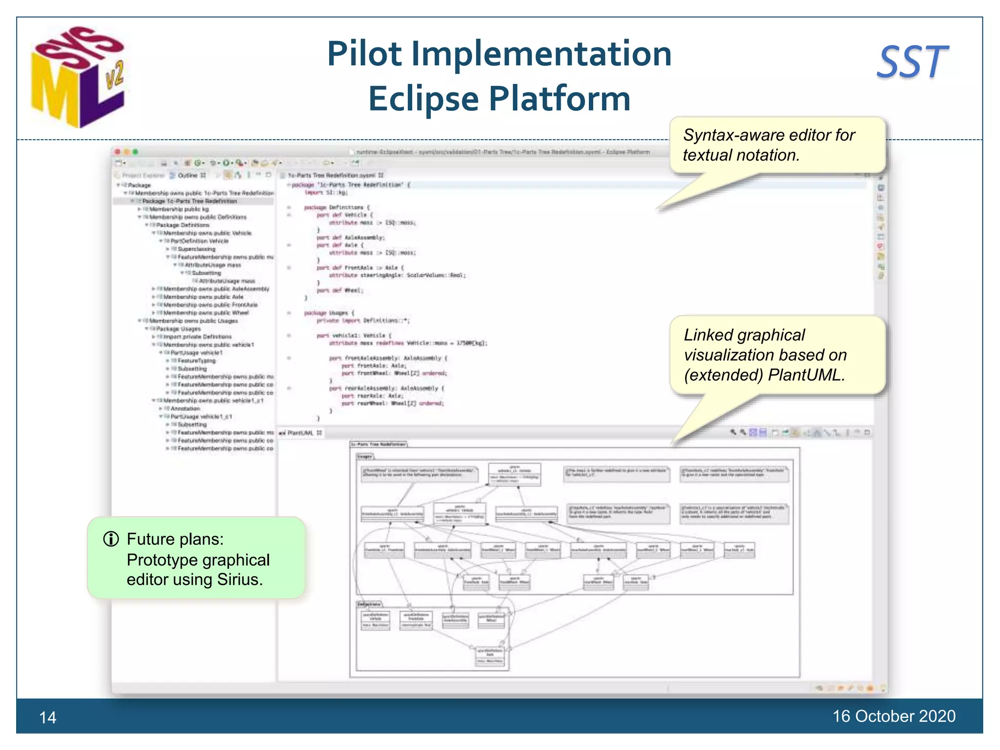
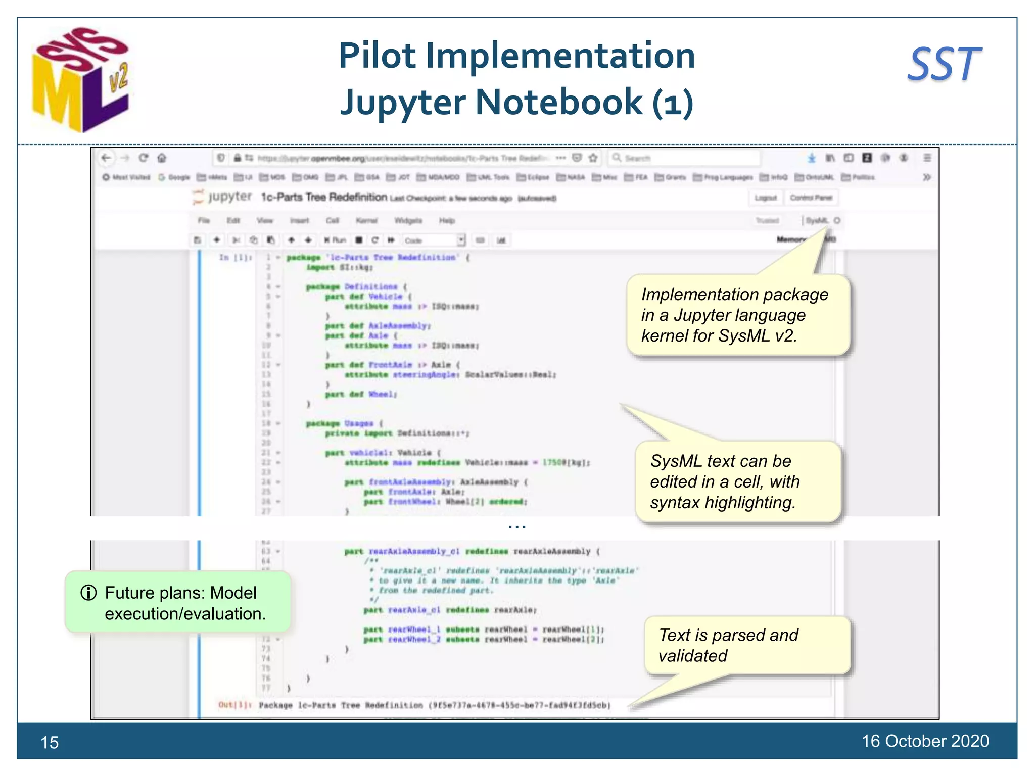
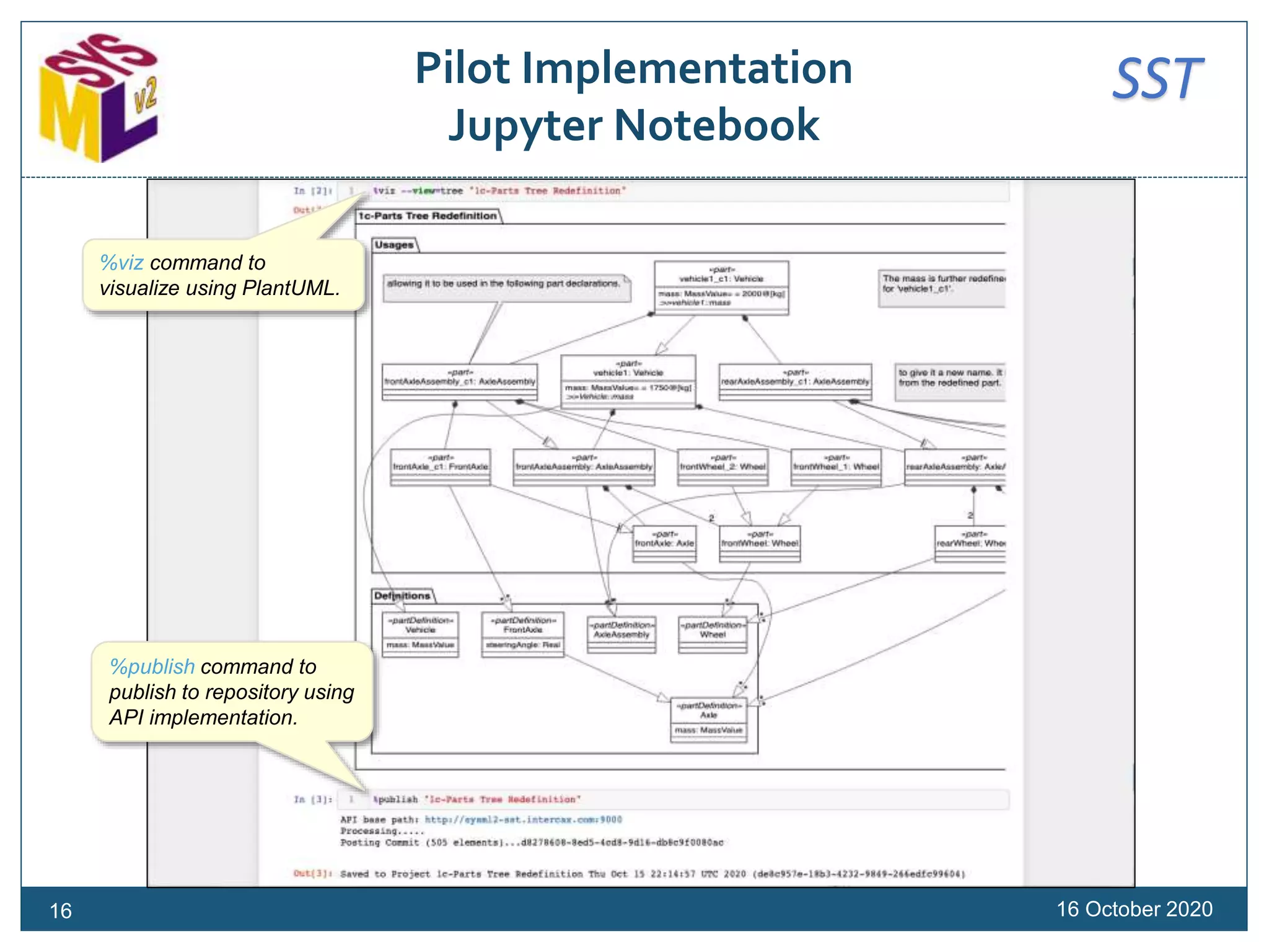
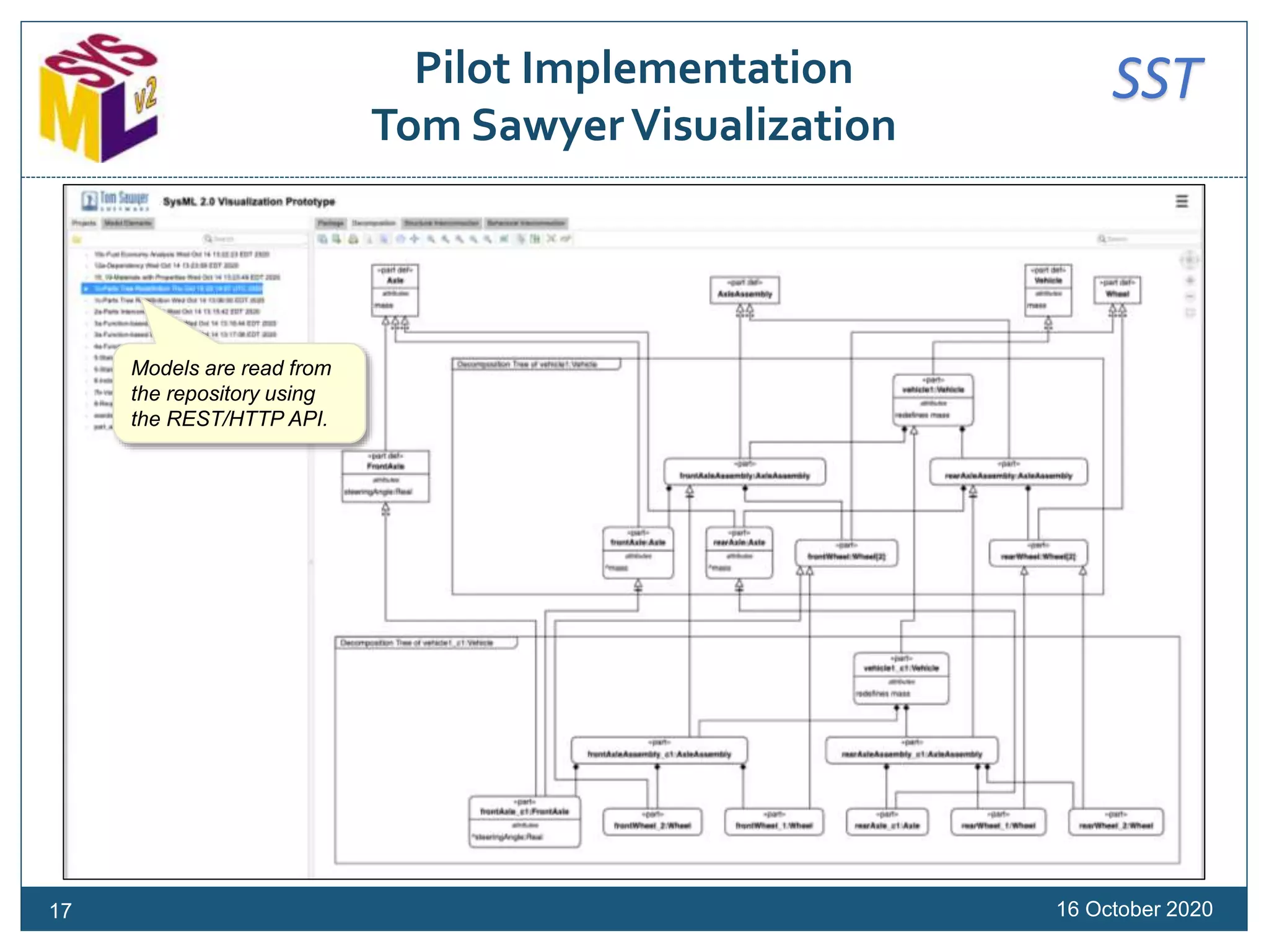
This document is a tutorial presented at a conference focused on the Systems Modeling Language (SysML) version 2, detailing its architecture, modeling capabilities, and pilot implementation. It outlines key elements such as metamodel structures, behavioral and structural modeling, and the involvement of various organizations in its development. The tutorial also discusses syntax and semantics, sample implementations, and documentation strategies for users engaging with SysML.