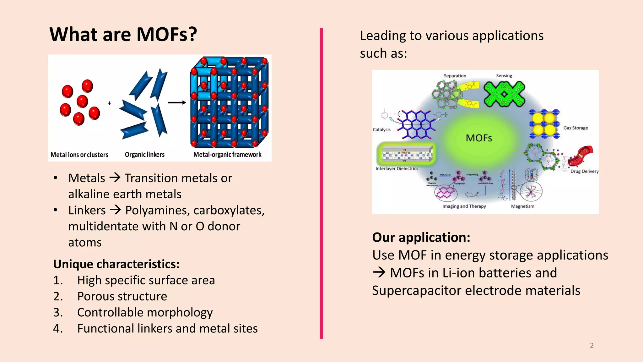
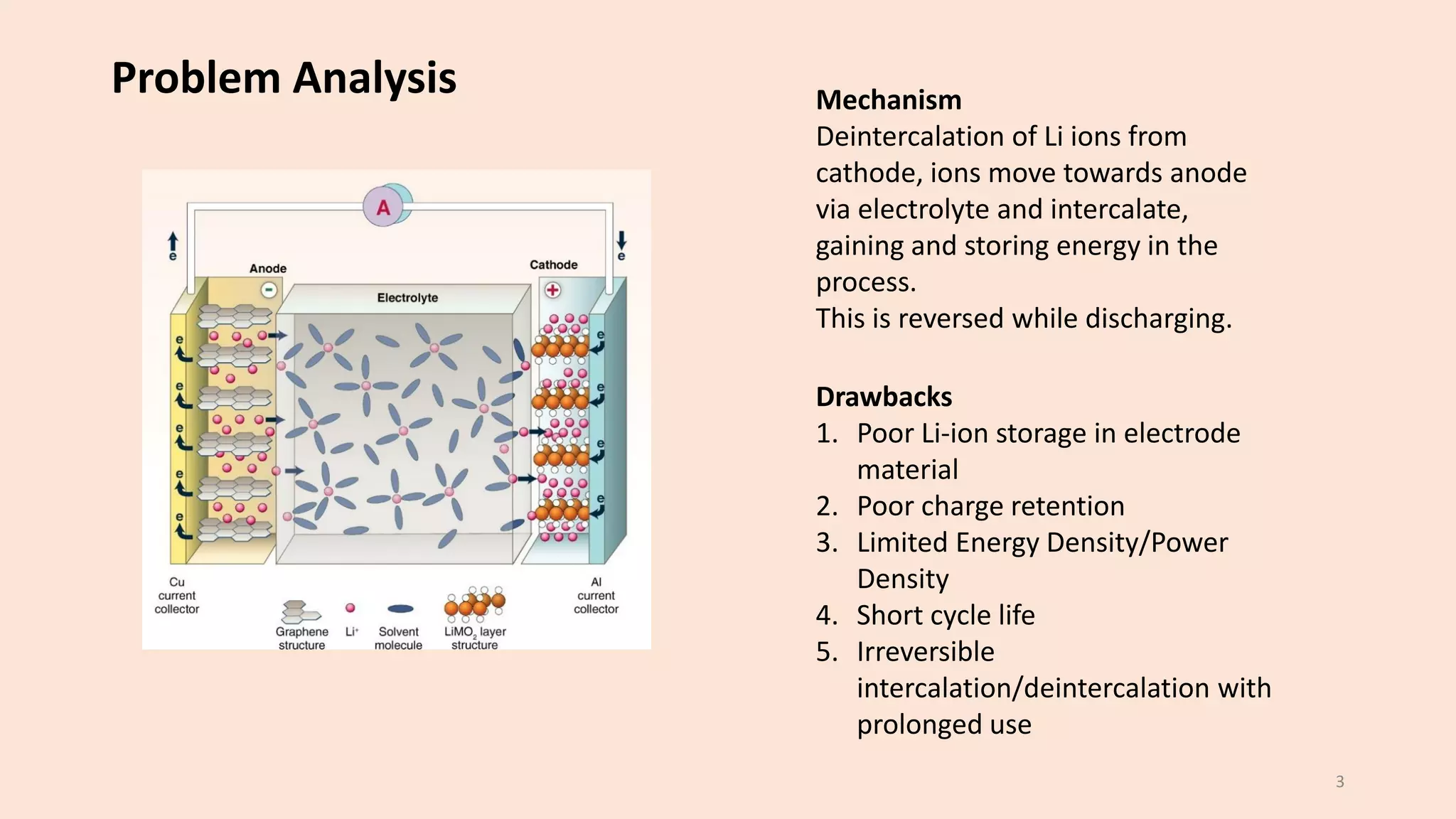
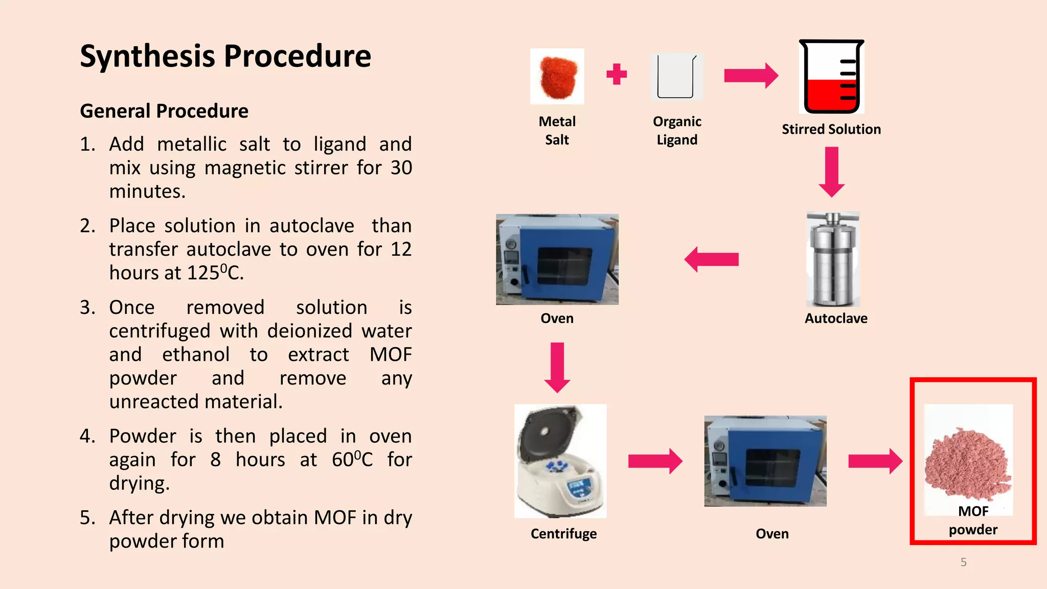
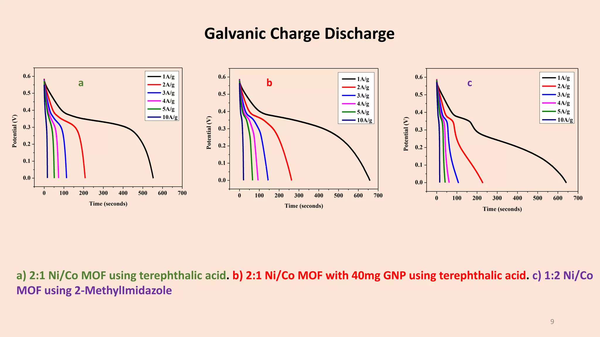
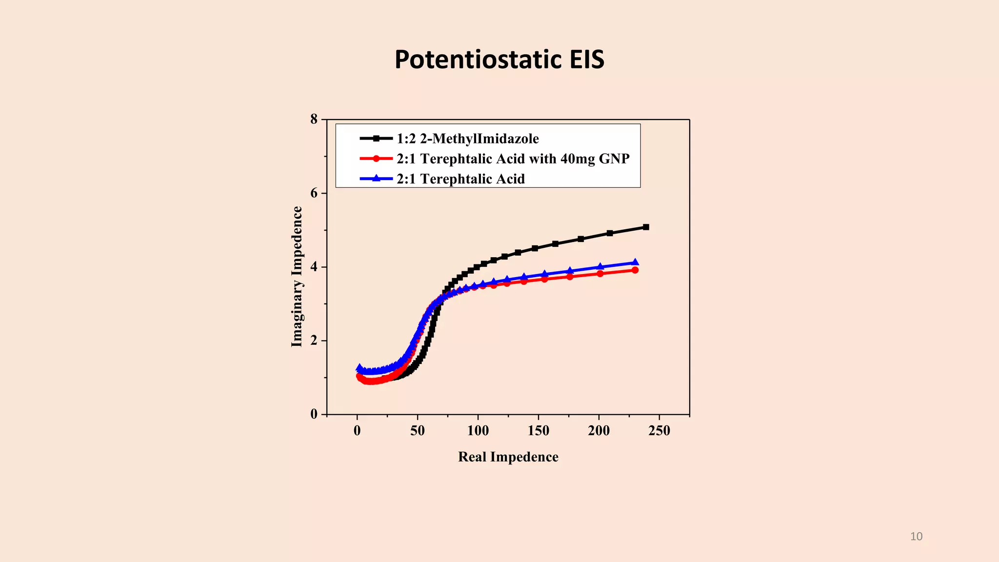
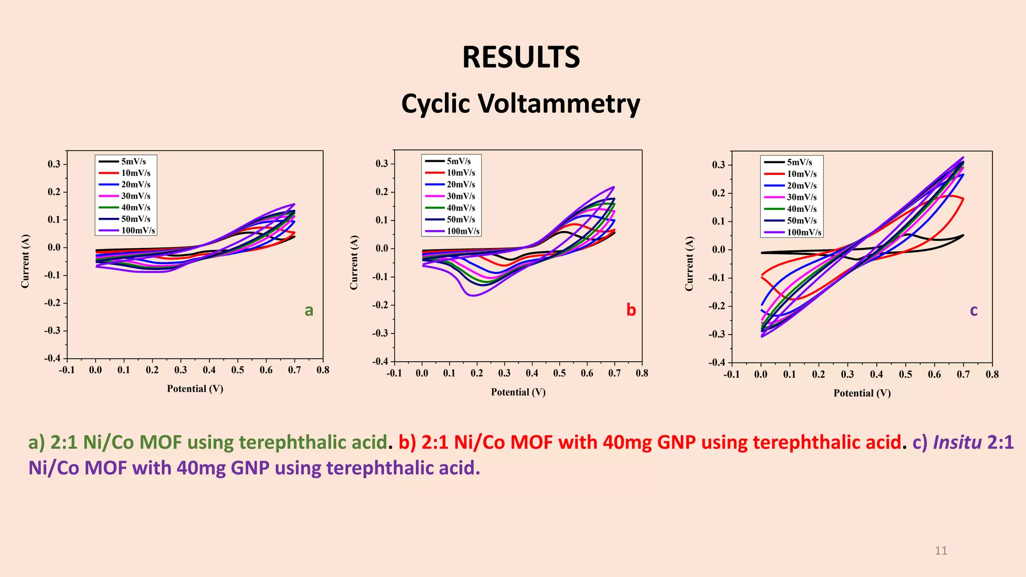
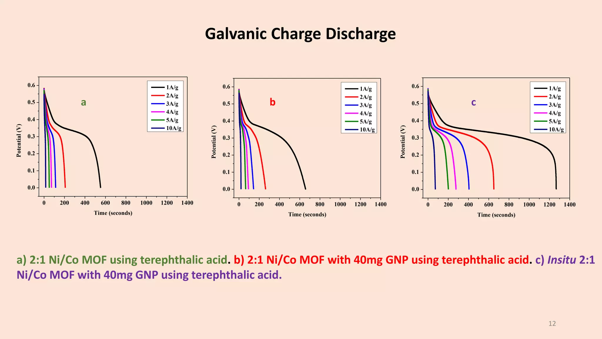
Synthesis and Characterization of MOF
based Composites for Energy Storage
Applications
Presentation by: Contacts:
Danyal Hakeem Jokhio 2017101 +92 335 0138929
Ahmed Raza Qureshi 2017047 +92 321 9957702
Amna Ali Dojki 2017071 +92 307 9266858
Advisor: Dr. Muhammad Ramzan Abdul Karim
Co-Advisor: Dr. Muhammad Zubair Khan
1
What are MOFs?
• Metals → Transition metals or
alkaline earth metals
• Linkers → Polyamines, carboxylates,
multidentate with N or O donor
atoms
Unique characteristics:
1. High specific surface area
2. Porous structure
3. Controllable morphology
4. Functional linkers and metal sites
Leading to various applications
such as:
Our application:
Use MOF in energy storage applications
→ MOFs in Li-ion batteries and
Supercapacitor electrode materials
2
Problem Analysis Mechanism
Deintercalation of Li ions from
cathode, ions move towards anode
via electrolyte and intercalate,
gaining and storing energy in the
process.
This is reversed while discharging.
Drawbacks
1. Poor Li-ion storage in electrode
material
2. Poor charge retention
3. Limited Energy Density/Power
Density
4. Short cycle life
5. Irreversible
intercalation/deintercalation with
prolonged use
3
Objectives
Overcome mentioned drawbacks by incorporating MOF/MOF-Composites in electrode materials
MOF significance and contribution to overcoming drawbacks
1. High surface area → Allow for greater adsorption of electrolyte and facilitate surface transport
2. Large pore volume → Increased storage capacity of Li-ions and therefore specific capacity
3. Metal sites as nodes → Act as active sites for redox reactions
4. Open structure → Allows for effective and reversible insertion/extraction for ions increasing cycle
life and stability
These characteristics will allow us to synthesize material capable of delivering high energy
density and power density, both! This is the requirement of future electronics.
4
Synthesis Procedure
General Procedure
1. Add metallic salt to ligand and
mix using magnetic stirrer for 30
minutes.
2. Place solution in autoclave than
transfer autoclave to oven for 12
hours at 1250C.
3. Once removed solution is
centrifuged with deionized water
and ethanol to extract MOF
powder and remove any
unreacted material.
4. Powder is then placed in oven
again for 8 hours at 600C for
drying.
5. After drying we obtain MOF in dry
powder form
Metal
Salt
Organic
Ligand
Stirred Solution
Oven Autoclave
Oven
Centrifuge
MOF
powder
5
Our Progress
Composition 1: Ni/Co nitrates salts with terephthalic ligand. 5 MOF powders were prepared by
varying the Ni/Co Ratio
Composition 2: Addition of GNP to 2:1 Ni/Co-MOF prepared in Experiment 1. 3 MOF powders were
prepared by varying the mass of GNPs added
Composition 4: Ni/Co nitrates salts with 2-MethylImidazole ligand. 5 MOF powders were prepared by
varying the Ni/Co Ratio
Composition 3: Addition of CNT to 2:1 Ni/Co-MOF prepared in Experiment 1. 3 MOF powders were
prepared by varying the mass of CNTs added
A total of 16 MOF powders were synthesized and analyzed by using electrochemical
characterization to find the optimum material systems.
6
Results at a Glance
Composition Ni/Co
ratio
Capacity of our
work/ C·g−1
Capacity as per
literature/
C·g−1
% improvement (if
any)
1 2:1 with
terephthalic
553.1 525.6 +5.23%
2 2:1 with 40mg GNP 658.8 525.6 +25.34%
3 2:1 with 40mg CNT 453.8 525.6 -13.6%
4 1:2 with 2-
MethylImidazole
642.4 339.3 +89.33%
5 Insitu 2:1 with
terephthalic &
40mg GNP
1264 525.6 +140.86%
6 1:2 with 2-MethIm
& 40mg GNP
124.8 339.3 -63.21%
7 1:2 with 2-MethIm
& 60mg GNP
103.6 339.3 -69.46%
RESULTS
-0.1 0.0 0.1 0.2 0.3 0.4 0.5 0.6 0.7 0.8
-0.10
-0.05
0.00
0.05
0.10
0.15
Current
(A)
Potential (V)
5mV/s
10mV/s
20mV/s
30mV/s
40mV/s
50mV/s
100mV/s
Cyclic Voltammetry
a) 2:1 Ni/Co MOF using terephthalic acid. b) 2:1 Ni/Co MOF with 40mg GNP using terephthalic acid. c) 1:2 Ni/Co
MOF using 2-MethylImidazole
-0.1 0.0 0.1 0.2 0.3 0.4 0.5 0.6 0.7 0.8
-0.20
-0.15
-0.10
-0.05
0.00
0.05
0.10
0.15
0.20
0.25
Current
(A)
Potential (V)
5mV/s
10mV/s
20mV/s
30mV/s
40mV/s
50mV/s
100mV/s
-0.1 0.0 0.1 0.2 0.3 0.4 0.5 0.6 0.7 0.8
-0.15
-0.10
-0.05
0.00
0.05
0.10
0.15
0.20
Current
(A)
Potential (V)
5mV/s
10mV/s
20mV/s
30mV/s
40mV/s
50mV/s
100mV/s
a b c
8
Galvanic Charge Discharge
0 100 200 300 400 500 600 700
0.0
0.1
0.2
0.3
0.4
0.5
0.6
Potential
(V)
Time (seconds)
1A/g
2A/g
3A/g
4A/g
5A/g
10A/g
0 100 200 300 400 500 600 700
0.0
0.1
0.2
0.3
0.4
0.5
0.6
Potential
(V) Time (seconds)
1A/g
2A/g
3A/g
4A/g
5A/g
10A/g
0 100 200 300 400 500 600 700
0.0
0.1
0.2
0.3
0.4
0.5
0.6
Potential
(V)
Time (seconds)
1A/g
2A/g
3A/g
4A/g
5A/g
10A/g
a b c
9
a) 2:1 Ni/Co MOF using terephthalic acid. b) 2:1 Ni/Co MOF with 40mg GNP using terephthalic acid. c) 1:2 Ni/Co
MOF using 2-MethylImidazole
Potentiostatic EIS
0 50 100 150 200 250
0
2
4
6
8
Imaginary
Impedence
Real Impedence
1:2 2-MethylImidazole
2:1 Terephtalic Acid with 40mg GNP
2:1 Terephtalic Acid
10
-0.1 0.0 0.1 0.2 0.3 0.4 0.5 0.6 0.7 0.8
-0.4
-0.3
-0.2
-0.1
0.0
0.1
0.2
0.3
Current
(A)
Potential (V)
5mV/s
10mV/s
20mV/s
30mV/s
40mV/s
50mV/s
100mV/s
-0.1 0.0 0.1 0.2 0.3 0.4 0.5 0.6 0.7 0.8
-0.4
-0.3
-0.2
-0.1
0.0
0.1
0.2
0.3
Current
(A)
Potential (V)
5mV/s
10mV/s
20mV/s
30mV/s
40mV/s
50mV/s
100mV/s
a b c
11
-0.1 0.0 0.1 0.2 0.3 0.4 0.5 0.6 0.7 0.8
-0.4
-0.3
-0.2
-0.1
0.0
0.1
0.2
0.3
Current
(A)
Potential (V)
5mV/s
10mV/s
20mV/s
30mV/s
40mV/s
50mV/s
100mV/s
a) 2:1 Ni/Co MOF using terephthalic acid. b) 2:1 Ni/Co MOF with 40mg GNP using terephthalic acid. c) Insitu 2:1
Ni/Co MOF with 40mg GNP using terephthalic acid.
RESULTS
Cyclic Voltammetry
0 200 400 600 800 1000 1200 1400
0.0
0.1
0.2
0.3
0.4
0.5
0.6
Potential
(V)
Time (seconds)
1A/g
2A/g
3A/g
4A/g
5A/g
10A/g
0 200 400 600 800 1000 1200 1400
0.0
0.1
0.2
0.3
0.4
0.5
0.6
Potential
(V) Time (seconds)
1A/g
2A/g
3A/g
4A/g
5A/g
10A/g
a b c
12
a) 2:1 Ni/Co MOF using terephthalic acid. b) 2:1 Ni/Co MOF with 40mg GNP using terephthalic acid. c) Insitu 2:1
Ni/Co MOF with 40mg GNP using terephthalic acid.
0 200 400 600 800 1000 1200 1400
0.0
0.1
0.2
0.3
0.4
0.5
0.6
Potential
(V)
Time (seconds)
1A/g
2A/g
3A/g
4A/g
5A/g
10A/g
Galvanic Charge Discharge
• Keeping results in mind, best compositions have been selected.
• To the best of out knowledge, our capacity of 1266 C·g−1 has surpasses
highest recorded capacity of 1000.3 C·g−1.
Next goals
• Physical characterization → XRD, SEM and BET
• Real time device assembly and testing
13
Conclusion
1. Xu, G., Nie, P., Dou, H., Ding, B., Li, L. and Zhang, X., 2017. Exploring metal organic frameworks for energy
storage in batteries and supercapacitors. Materials today, 20(4), pp.191-209.
2. Wang, L., Han, Y., Feng, X., Zhou, J., Qi, P. and Wang, B., 2016. Metal–organic frameworks for energy
storage: Batteries and supercapacitors. Coordination Chemistry Reviews, 307, pp.361-381.
3. Liang, Z., Qu, C., Guo, W., Zou, R. and Xu, Q., 2018. Pristine metal–organic frameworks and their
composites for energy storage and conversion. Advanced Materials, 30(37), p.1702891.
4. Jia, J., Xu, F., Long, Z., Hou, X. and Sepaniak, M.J., 2013. Metal–organic framework MIL-53 (Fe) for highly
selective and ultrasensitive direct sensing of MeHg+. Chemical Communications, 49(41), pp.4670-4672.
5. Figure 1, Copyright (2018), the author. Licensee MDPI, Basel, Switzerland.
6. Figure 3, Schematic of a lithium-ion battery (LIB) (Dunn et al. 2011)
14
References
Please feel free to reach out and ask any questions!
15
Thank You
16
Team Details
Amna Ali Dojki
• u2017071@giki.edu.pk
• amnaalidojki4@gmail.com
• BS in Materials Engineering, Specialization: Nanotechnology
• GIK Institute, Pakistan
Ahmed Raza Qureshi
• u2017047@giki.edu.pk
• ahmedrqureshi179@gmail.com
• BS in Materials Engineering, Specialization: Nanotechnology
• GIK Institute, Pakistan
Danyal Hakeem Jokhio
• u2017071@giki.edu.pk
• amnaalidojki4@gmail.com
• BS in Materials Engineering, Specialization: Nanotechnology
• GIK Institute, Pakistan

Synthesis and Characterization of MOF based Composites for Energy storage applications

  • 1.
    Synthesis and Characterizationof MOF based Composites for Energy Storage Applications Presentation by: Contacts: Danyal Hakeem Jokhio 2017101 +92 335 0138929 Ahmed Raza Qureshi 2017047 +92 321 9957702 Amna Ali Dojki 2017071 +92 307 9266858 Advisor: Dr. Muhammad Ramzan Abdul Karim Co-Advisor: Dr. Muhammad Zubair Khan 1
  • 2.
    What are MOFs? •Metals → Transition metals or alkaline earth metals • Linkers → Polyamines, carboxylates, multidentate with N or O donor atoms Unique characteristics: 1. High specific surface area 2. Porous structure 3. Controllable morphology 4. Functional linkers and metal sites Leading to various applications such as: Our application: Use MOF in energy storage applications → MOFs in Li-ion batteries and Supercapacitor electrode materials 2
  • 3.
    Problem Analysis Mechanism Deintercalationof Li ions from cathode, ions move towards anode via electrolyte and intercalate, gaining and storing energy in the process. This is reversed while discharging. Drawbacks 1. Poor Li-ion storage in electrode material 2. Poor charge retention 3. Limited Energy Density/Power Density 4. Short cycle life 5. Irreversible intercalation/deintercalation with prolonged use 3
  • 4.
    Objectives Overcome mentioned drawbacksby incorporating MOF/MOF-Composites in electrode materials MOF significance and contribution to overcoming drawbacks 1. High surface area → Allow for greater adsorption of electrolyte and facilitate surface transport 2. Large pore volume → Increased storage capacity of Li-ions and therefore specific capacity 3. Metal sites as nodes → Act as active sites for redox reactions 4. Open structure → Allows for effective and reversible insertion/extraction for ions increasing cycle life and stability These characteristics will allow us to synthesize material capable of delivering high energy density and power density, both! This is the requirement of future electronics. 4
  • 5.
    Synthesis Procedure General Procedure 1.Add metallic salt to ligand and mix using magnetic stirrer for 30 minutes. 2. Place solution in autoclave than transfer autoclave to oven for 12 hours at 1250C. 3. Once removed solution is centrifuged with deionized water and ethanol to extract MOF powder and remove any unreacted material. 4. Powder is then placed in oven again for 8 hours at 600C for drying. 5. After drying we obtain MOF in dry powder form Metal Salt Organic Ligand Stirred Solution Oven Autoclave Oven Centrifuge MOF powder 5
  • 6.
    Our Progress Composition 1:Ni/Co nitrates salts with terephthalic ligand. 5 MOF powders were prepared by varying the Ni/Co Ratio Composition 2: Addition of GNP to 2:1 Ni/Co-MOF prepared in Experiment 1. 3 MOF powders were prepared by varying the mass of GNPs added Composition 4: Ni/Co nitrates salts with 2-MethylImidazole ligand. 5 MOF powders were prepared by varying the Ni/Co Ratio Composition 3: Addition of CNT to 2:1 Ni/Co-MOF prepared in Experiment 1. 3 MOF powders were prepared by varying the mass of CNTs added A total of 16 MOF powders were synthesized and analyzed by using electrochemical characterization to find the optimum material systems. 6
  • 7.
    Results at aGlance Composition Ni/Co ratio Capacity of our work/ C·g−1 Capacity as per literature/ C·g−1 % improvement (if any) 1 2:1 with terephthalic 553.1 525.6 +5.23% 2 2:1 with 40mg GNP 658.8 525.6 +25.34% 3 2:1 with 40mg CNT 453.8 525.6 -13.6% 4 1:2 with 2- MethylImidazole 642.4 339.3 +89.33% 5 Insitu 2:1 with terephthalic & 40mg GNP 1264 525.6 +140.86% 6 1:2 with 2-MethIm & 40mg GNP 124.8 339.3 -63.21% 7 1:2 with 2-MethIm & 60mg GNP 103.6 339.3 -69.46%
  • 8.
    RESULTS -0.1 0.0 0.10.2 0.3 0.4 0.5 0.6 0.7 0.8 -0.10 -0.05 0.00 0.05 0.10 0.15 Current (A) Potential (V) 5mV/s 10mV/s 20mV/s 30mV/s 40mV/s 50mV/s 100mV/s Cyclic Voltammetry a) 2:1 Ni/Co MOF using terephthalic acid. b) 2:1 Ni/Co MOF with 40mg GNP using terephthalic acid. c) 1:2 Ni/Co MOF using 2-MethylImidazole -0.1 0.0 0.1 0.2 0.3 0.4 0.5 0.6 0.7 0.8 -0.20 -0.15 -0.10 -0.05 0.00 0.05 0.10 0.15 0.20 0.25 Current (A) Potential (V) 5mV/s 10mV/s 20mV/s 30mV/s 40mV/s 50mV/s 100mV/s -0.1 0.0 0.1 0.2 0.3 0.4 0.5 0.6 0.7 0.8 -0.15 -0.10 -0.05 0.00 0.05 0.10 0.15 0.20 Current (A) Potential (V) 5mV/s 10mV/s 20mV/s 30mV/s 40mV/s 50mV/s 100mV/s a b c 8
  • 9.
    Galvanic Charge Discharge 0100 200 300 400 500 600 700 0.0 0.1 0.2 0.3 0.4 0.5 0.6 Potential (V) Time (seconds) 1A/g 2A/g 3A/g 4A/g 5A/g 10A/g 0 100 200 300 400 500 600 700 0.0 0.1 0.2 0.3 0.4 0.5 0.6 Potential (V) Time (seconds) 1A/g 2A/g 3A/g 4A/g 5A/g 10A/g 0 100 200 300 400 500 600 700 0.0 0.1 0.2 0.3 0.4 0.5 0.6 Potential (V) Time (seconds) 1A/g 2A/g 3A/g 4A/g 5A/g 10A/g a b c 9 a) 2:1 Ni/Co MOF using terephthalic acid. b) 2:1 Ni/Co MOF with 40mg GNP using terephthalic acid. c) 1:2 Ni/Co MOF using 2-MethylImidazole
  • 10.
    Potentiostatic EIS 0 50100 150 200 250 0 2 4 6 8 Imaginary Impedence Real Impedence 1:2 2-MethylImidazole 2:1 Terephtalic Acid with 40mg GNP 2:1 Terephtalic Acid 10
  • 11.
    -0.1 0.0 0.10.2 0.3 0.4 0.5 0.6 0.7 0.8 -0.4 -0.3 -0.2 -0.1 0.0 0.1 0.2 0.3 Current (A) Potential (V) 5mV/s 10mV/s 20mV/s 30mV/s 40mV/s 50mV/s 100mV/s -0.1 0.0 0.1 0.2 0.3 0.4 0.5 0.6 0.7 0.8 -0.4 -0.3 -0.2 -0.1 0.0 0.1 0.2 0.3 Current (A) Potential (V) 5mV/s 10mV/s 20mV/s 30mV/s 40mV/s 50mV/s 100mV/s a b c 11 -0.1 0.0 0.1 0.2 0.3 0.4 0.5 0.6 0.7 0.8 -0.4 -0.3 -0.2 -0.1 0.0 0.1 0.2 0.3 Current (A) Potential (V) 5mV/s 10mV/s 20mV/s 30mV/s 40mV/s 50mV/s 100mV/s a) 2:1 Ni/Co MOF using terephthalic acid. b) 2:1 Ni/Co MOF with 40mg GNP using terephthalic acid. c) Insitu 2:1 Ni/Co MOF with 40mg GNP using terephthalic acid. RESULTS Cyclic Voltammetry
  • 12.
    0 200 400600 800 1000 1200 1400 0.0 0.1 0.2 0.3 0.4 0.5 0.6 Potential (V) Time (seconds) 1A/g 2A/g 3A/g 4A/g 5A/g 10A/g 0 200 400 600 800 1000 1200 1400 0.0 0.1 0.2 0.3 0.4 0.5 0.6 Potential (V) Time (seconds) 1A/g 2A/g 3A/g 4A/g 5A/g 10A/g a b c 12 a) 2:1 Ni/Co MOF using terephthalic acid. b) 2:1 Ni/Co MOF with 40mg GNP using terephthalic acid. c) Insitu 2:1 Ni/Co MOF with 40mg GNP using terephthalic acid. 0 200 400 600 800 1000 1200 1400 0.0 0.1 0.2 0.3 0.4 0.5 0.6 Potential (V) Time (seconds) 1A/g 2A/g 3A/g 4A/g 5A/g 10A/g Galvanic Charge Discharge
  • 13.
    • Keeping resultsin mind, best compositions have been selected. • To the best of out knowledge, our capacity of 1266 C·g−1 has surpasses highest recorded capacity of 1000.3 C·g−1. Next goals • Physical characterization → XRD, SEM and BET • Real time device assembly and testing 13 Conclusion
  • 14.
    1. Xu, G.,Nie, P., Dou, H., Ding, B., Li, L. and Zhang, X., 2017. Exploring metal organic frameworks for energy storage in batteries and supercapacitors. Materials today, 20(4), pp.191-209. 2. Wang, L., Han, Y., Feng, X., Zhou, J., Qi, P. and Wang, B., 2016. Metal–organic frameworks for energy storage: Batteries and supercapacitors. Coordination Chemistry Reviews, 307, pp.361-381. 3. Liang, Z., Qu, C., Guo, W., Zou, R. and Xu, Q., 2018. Pristine metal–organic frameworks and their composites for energy storage and conversion. Advanced Materials, 30(37), p.1702891. 4. Jia, J., Xu, F., Long, Z., Hou, X. and Sepaniak, M.J., 2013. Metal–organic framework MIL-53 (Fe) for highly selective and ultrasensitive direct sensing of MeHg+. Chemical Communications, 49(41), pp.4670-4672. 5. Figure 1, Copyright (2018), the author. Licensee MDPI, Basel, Switzerland. 6. Figure 3, Schematic of a lithium-ion battery (LIB) (Dunn et al. 2011) 14 References
  • 15.
    Please feel freeto reach out and ask any questions! 15 Thank You
  • 16.
    16 Team Details Amna AliDojki • u2017071@giki.edu.pk • amnaalidojki4@gmail.com • BS in Materials Engineering, Specialization: Nanotechnology • GIK Institute, Pakistan Ahmed Raza Qureshi • u2017047@giki.edu.pk • ahmedrqureshi179@gmail.com • BS in Materials Engineering, Specialization: Nanotechnology • GIK Institute, Pakistan Danyal Hakeem Jokhio • u2017071@giki.edu.pk • amnaalidojki4@gmail.com • BS in Materials Engineering, Specialization: Nanotechnology • GIK Institute, Pakistan