Download to read offline
![International Research Journal of Engineering and Technology (IRJET) e-ISSN: 2395 -0056
Volume: 04 Issue: 06 | June-2017 www.irjet.net p-ISSN: 2395-0072
© 2017, IRJET | Impact Factor value: 5.181 | ISO 9001:2008 Certified Journal | Page 123
Switched DC Sources Based Novel Multilevel Inverter
Tekale Anil A.1, Ghule Puja R.2, Thombare Shubhangi s.3, Agale Priyanka B.4
1Asst. Professor, Electrical Engg Dept, HSBPVT’s COE. Kashti, Maharashtra, India.
2,3,4Student, Electrical Engg Dept, HSBPVT’s COE. Kashti, Maharashtra, India.
---------------------------------------------------------------------***---------------------------------------------------------------------
Abstract – This paper we are represent the five-level
inverter, it reduces the no. of switches and gives the large
no. of output levels. It comprises two input dc sources
connected in opposite polarities with one another through
power switches. Each input dc level presents in the stepped
load voltage either separately or in additive combinations
with other input levels.
This approach results in reduced number of power switches
as compared to existing topologies. The operating principle
of the proposed topology is demonstrated with the help of a
single –phase five-level inverter. An exhaustive comparison
of the proposed topology is made against the existing
cascaded H-bridge topology.
Key Words: Existing topologies, five-level inverter, reduced
component count, pulse width modulation (PWM), total
harmonic distortion (THD).
1. INTRODUCTION
In the last few decades, five-level voltage-source
inverters have come forth as a viable solution for high-
power dc-to-ac conversion applications [1]. A five-level
inverter is a linkage structure of multiple input dc levels
(obtained from dc sources and/or capacitors) and power
semiconductor devices to synthesize a staircase
waveform. Voltage stresses practiced by the power
switches are lower as compared to the overall operating
voltage level [2]. In addition, the multilevel waveform has
improved harmonic profile as compared to a two-level
waveform obtained from ordinary inverters. Other
benefits of MLIs are reduced dv/dt stress on the load and
possibility of fault-tolerant operation [3]. Researchers are
also exploring approaches to employ MLIs for low-power
applications [4]. The nature of the multilevel waveform is
enhanced by increasing the number of levels. However, in
existing topology used large number of power switches
and complex gate drive circuit. This increases complexity
of system and cost and reduces the reliability and
efficiency of system. For a efficient system requires reduce
the number of switches and gate drive circuit [5].
However, there is a expressive increase in the number of
power switches, the number of switches conducting
concomitantly, and the overall cost of the system with the
increase in the number of output levels. Researchers,
therefore, proceed to focus on reducing the component
count in multilevel topologies through several approaches.
In this paper, a new topology is proposed in which
alternate dc sources are linked in adverse polarities via
power switches. This approach significantly lessens the
number of power switches needed as compared to the
existing topologies. Furthermore, for regular input dc
sources, the proposed topology presents similarity with
the CHB topology in two forms: 1) it’s necessities multiple
isolated input dc voltages; and 2) input dc voltage levels
can be concrete into complete additional values. Thus, the
topology can be used as a utility interface for renewable
energy systems where a more number of isolated dc
sources are available [2], [7], [9]. It can be used in
medium-voltage drive applications where a phase-shifting
transformer with multiple secondary windings is generally
applied (primarily for the reduction of line current
distortion), thus providing isolated dc sources [6]. The
applications of the proposed topology for battery-powered
(such as electric vehicles and submarine propulsion). This
paper is arranged as follows. Section 2 introduces the
generalized structure of the proposed topology with
mathematical formulations. The operating principle of the
topology is also defined in this section with the help of a
five-level single phase inverter. Terms for the calculation
of losses are present in Section 3. A comparison of the
proposed topology with existing topologies is presented in
Section 4. In Section 5 conclusions are summarized.
2. PROPOSED MULTILEVEL TOPOLOGY
In that section, we are introduced the structure of
proposed topology, and its operating principle is
illustrated with the help of a single-phase five-level
inverter. Terms’ for output voltage, source currents,
voltage stresses, etc., are also introduced.
2.1 Generalized Structure
Fig.1 shows that a generalized single phase structure
of five-level inverter. its having a n number of DC sources .
linkage structure of sources as like a positive terminal of
one DC source connected to negative terminal of another
DC source , in this way we are linkage the n number of DC
source .in fig. 1 shows input sources as like Ej ( where j=1 to
n) . Source current indicated of each source as like ij( t) .
We are uses power switches in that as like MOSFET,
IGBT.AND ANTIPARALLEL DIODES are used across with
power switches. In fig.1 we shows IGBT switches with an
anti-parallel diodes and complementary pairs are
designated as like as (Tj ,Tj
’) ( where, j=1 to n+1). In fig. 1
indicated nodal voltage and current are VL (t) and iL (t)
respectively.](https://image.slidesharecdn.com/irjet-v4i619-180120095429/75/Switched-DC-Sources-Based-Novel-Multilevel-Inverter-1-2048.jpg)
![International Research Journal of Engineering and Technology (IRJET) e-ISSN: 2395 -0056
Volume: 04 Issue: 06 | June-2017 www.irjet.net p-ISSN: 2395-0072
© 2017, IRJET | Impact Factor value: 5.181 | ISO 9001:2008 Certified Journal | Page 124
Fig -1: Generalized single-phase construction of the
proposed topology.
2.2 Working Principle
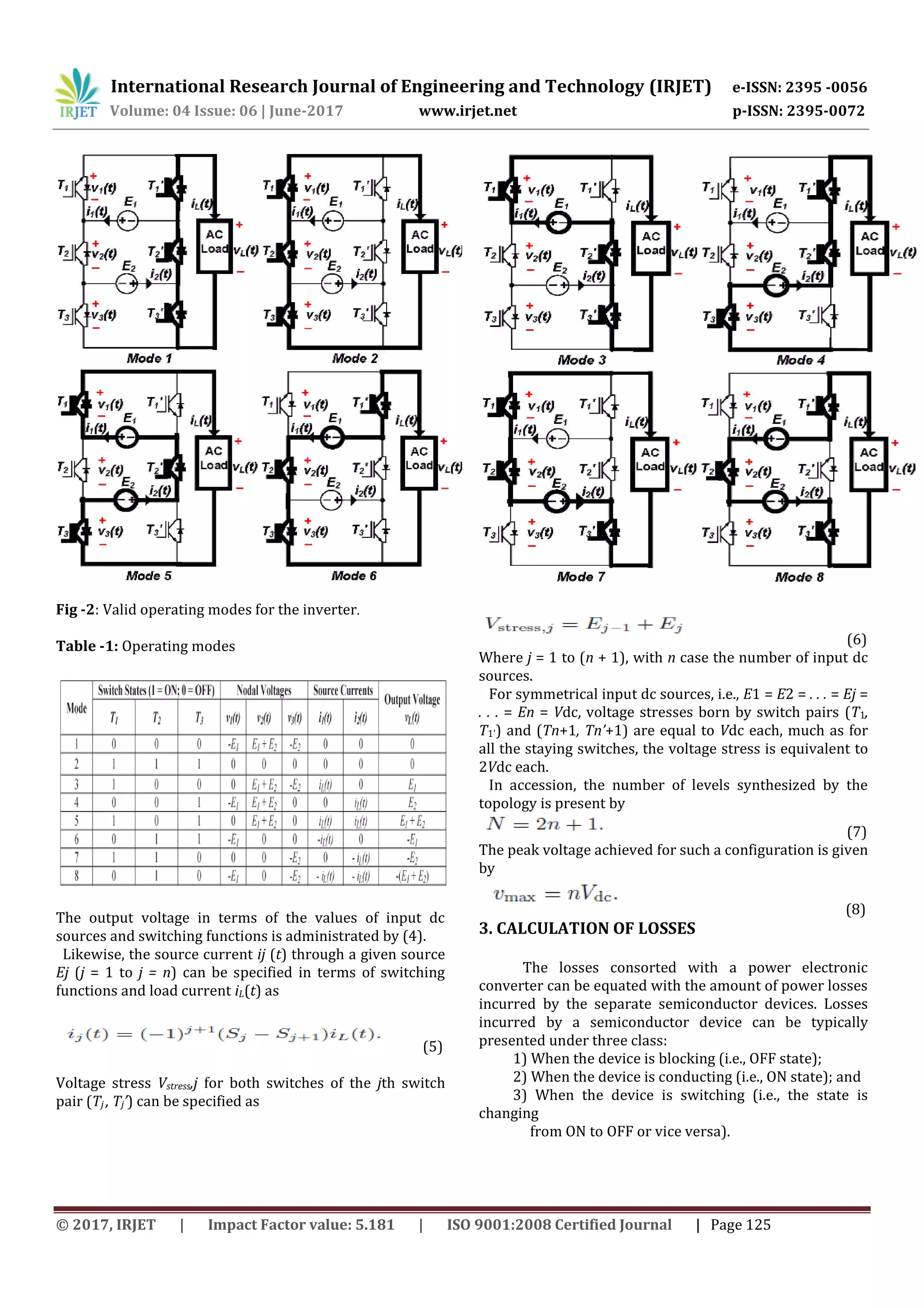
The working principle of the proposed topology is
defined with the help of a single-phase inverter with two
input dc sources E1 and E2, as shown in Fig. 2. It has three
couples of active switches (Tj, Tj’) (j = 1, 2, 3). Since the
elements of these couples are counterparty and it’s having
eight valid operating modes. These modes are shown in
Fig. 3 and are briefed in Table 1 along with nodal voltages
and source currents. Using these operating modes shown
in Fig. 3, the load is supplied with five levels, viz., ±Vdc,
±2Vdc, and zero for E1 = E2 = Vdc. With such a regular
source configuration, modes 3 and 4 become excessive for
output level +Vdc, while modes 6 and 7 become redundant
for output level −Vdc. It is main to note here that, for
whole positive voltage levels and one “zero” level (modes
1, 3, 4, and 5), switch T2’ always conducts, while for whole
negative voltage levels and another “zero” level (modes 2,
6, 7, and 8), switch T2 always conducts. Accordingly, it is
possible to operate these two switches at the fundamental
frequency to acquire five output levels. To do so, modes 1,
3 (or 4), and 5 need to be applied for the synthesis of
positive levels (including a “zero” level), and modes 2, 6
(or 7), and 8 need to be applied for the synthesis of
negative voltage levels (contains a “zero” level). It is also
important to declare here that dc source voltages have
been assumed to be equal in this work. In usage, they
might differ (e.g., due to different states of charge of
batteries or due to shading of some cells if the sources are
becoming from a photovoltaic (PV) system). To account
for
Fig -2: Single-phase inverter based on the proposed
topology with couple input sources.
this deviation, both hardware-based solutions (e.g., using
separate dc–dc converters [8]) and control-algorithm-
based solutions (e.g., battery adjusting methodology [19])
can be appliance.
2.3 Mathematical Formulations
According to Fig. 1, switches Tj and Tj’ (j = 1 to n + 1)
operate correspondingly. Let Sj be a switching function
complementarily to switch Tj presented as
(1)
Then, the load terminal voltage vl (t) can be specified in
terms of nodal voltages vj (t) as
(2)
Where
(3)
Using j = 1 to j = n + 1 & E0 = En+1 = 0 as there are no such
sources.
Using (2) and (3)
(4)](https://image.slidesharecdn.com/irjet-v4i619-180120095429/75/Switched-DC-Sources-Based-Novel-Multilevel-Inverter-2-2048.jpg)
![International Research Journal of Engineering and Technology (IRJET) e-ISSN: 2395 -0056
Volume: 04 Issue: 06 | June-2017 www.irjet.net p-ISSN: 2395-0072
© 2017, IRJET | Impact Factor value: 5.181 | ISO 9001:2008 Certified Journal | Page 127
Table -2: Comparison between Existing Topology with
Proposed Topology
5. CONCLUSION
A Five-Level inverter are gaining attention, exertion
are being directed toward attenuating the device count for
increased number of output levels. A novel topology for
Five-Level inverter has been proposed in this paper to
attenuate the device count. The operating principle of the
proposed topology has been illustrated and mathematical
formulations suiting to output voltage, source currents,
voltage stresses on switches, and power losses have been
eliminate. Comparisons of the proposed topology with
existing topologies acknowledge that the proposed
topology significantly reduces the number of power
switches and associated gate driver circuits.
REFERENCES
[1] S. Kouro, M. Malinowski, K. Gopakumar, J. Pou, L.
Franquelo, B. Wu, J. Rodriguez, M. Perez, and Leon, “Recent
advances and industrial applications of multilevel
converters,” IEEE Trans. Ind. Electron., vol. 57, no. 8, pp.
2553–2580, Aug. 2010.
[2] G. Buticchi, E. Lorenzani, and Franceschini, “A five-level
single-phase grid-connected converter for renewable
distributed systems,” IEEE Trans. Ind. Electron., vol. 60,
no. 3, pp. 906–918, Mar. 2013.
[3] J. Rodriguez, J. Lai, and F. ZhengPeng, “Multilevel
inverters: A survey of topologies, controls, applications,”
IEEE Trans. Ind. Electron., vol. 49, no. 4, pp. 724–738, Aug.
2002.
[4] S. De, D. Banerjee, K. Siva Kumar, K. Gopakumar, R.
Ramchand, and Patel, “Multilevel inverters for low-power
application,” IET Power Electronics, vol. 4, no. 4, pp. 384–
392, Apr. 2011.
[5] M. Malinowski, K. Gopakumar, J. Rodriguez, “A survey
on cascaded multilevel inverters,” IEEE Trans. Ind.
Electron., vol. 57, no. 7, pp. 2197–2206, Jul. 2010.
[6] J. Rodriguez, S. Bernet, J. O. Pontt, and S. Kouro,
“Multilevel voltage-source-converter topologies for
industrial medium-voltage drives,” IEEE Trans. Ind.
Electron., vol. 54, no. 6, pp. 2930–2945, Dec. 2007.
[7] L. M. Tolbert and F. Peng, “Multilevel converters as a
utility interface for renewable energy systems,” in Proc.
IEEE Power Eng. Soc. Summer Meeting, 2000, vol. 2, pp.
1271–1274.
[8] J. Ebrahimi, and G. B. Gharehpetian, “A new multilevel
converter topology with reduced number of power
electronic components,” IEEE Trans. Ind. Electron., vol. 59,
no. 2, pp. 655–667, Feb. 2012.
[9] Y. Hinago , “A switched-capacitor inverter using series/
parallel conversion with inductive load,” IEEE Trans. Ind.
Electron., vol. 59, no. 2, pp. 878–887, Feb. 2012.](https://image.slidesharecdn.com/irjet-v4i619-180120095429/75/Switched-DC-Sources-Based-Novel-Multilevel-Inverter-5-2048.jpg)

This document summarizes a research paper on a novel multilevel inverter topology that uses switched DC sources. The proposed topology connects alternate DC sources in opposite polarities through power switches, significantly reducing the number of switches compared to existing topologies. The operating principle of a single-phase five-level inverter using two DC sources is demonstrated. Mathematical equations are provided to describe the output voltage, source currents, voltage stresses on switches, and number of output levels for the generalized topology. Losses associated with the power switches are also discussed.