Thank you for the presentation. Proper pump sizing and selection is critical for well performance and reliability. Please let me know if you have any other questions!
How it works
1. Each combination of a
chamber with an impeller
is referred to as a “stage”
or “bowl”
2. Each stage adds lift to the
pump
3. The impellers are directly
connected to the motor
which creates flow.
4. As with all variable
displacement pumps:
flow rate is inversely
related to the head
pressure.
7.
Pump Parameters
Q: Sowhat determines the necessary size of the pump?
A: Flow rate & the amount of lift required.
1. Flow Rate: Make sure the aquifer is capable of
supporting your desired flow rate. Do you have any
pump test data? Why not?
2. Lift: Submersible pumps do not build pressure. They
provide lift which overcomes head pressure, which is
measured in feet.
The head pressure against which a submersible pump
operates is referred to as…
TOTAL DYNAMIC HEAD (TDH)
8.
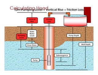
TDH=Pumping Level +Vertical Rise + Friction Loss
Calculating Head
Submergence
Pump Depth
Well Depth
Pumping
Level
Draw Down
Static
Water
Level
Pump
Vertical
Rise
Friction
Loss
9.
Friction Loss
Q: Howdo I quantify friction loss?
Friction Loss is a result of water’s resistance to flow.
It’s affected by…
• Flow Rate
• Pipe diameter and type
• Number and type of fittings and valves
A: Darcy-Weisbach equation:
Hf = ∆p/γ = f (L/D)x(V/2g)
Or you can just look it up!
10.
Pump Selection
Q: SoI know my flow rate and system TDH. Now what?
A: Start shopping!
1. Pump suppliers publish pump curves for all the various
models. Select your flow range…
12.
Pump Selection
Q: SoI know my flow rate and system TDH. Now what?
A: Start shopping!
1. Pump suppliers publish pump curves for all the various
models. Select your flow range…
2. They also provide “easy selection charts” which are
just pump curves for several models of pumps in a
table format.
14.
Worksheet:
Peter Piper pickeda peck
of pickled pumps!
How to size a pump:
1. What is required/desired flow (GPM)
2. Determine TDH
3. Consult Pump Curve(s)
4. Select wire size
15.
How to sizea pump:
What is required/desired flow? 5 GPM
Determine TDH
First, let’s calculate friction loss!
Friction loss = total length X friction loss (straight pipe) factor + friction loss (fittings)
Friction loss = (_____’ X _____’/_____’) + (__’ X __)
Friction loss = _____’ + _____’
Friction loss = _____’ Head Pressure
Now we can calculate TDH!
TDH = pumping level + vertical rise + friction loss
TDH = _____’ + _____’ + _____’
TDH = _____’
Now that we know the TDH and required/desired flow, we can select a pump from a performance
curve.
Which 4” pump/motor combination will deliver 5 GPM at the calculated TDH?
___________________.
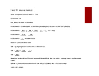
How to sizea pump:
What is required/desired flow? 5 GPM
Determine TDH
First, let’s calculate friction loss!
Friction loss = total length X friction loss (straight pipe) factor + friction loss (fittings)
Friction loss = ( 922 ’ X 1.8 ’/ 100 ’) + ( 3 ’ X 2 ) (1.8’/100’)
Friction loss = 16.60 ’ + .108 ’
Friction loss = 17 ’ Head Pressure
Now we can calculate TDH!
TDH = pumping level + vertical rise + friction loss
TDH = 500 ’ + 222 ’ + 17 ’
TDH = 739 ’
Now that we know the TDH and required/desired flow, we can select a pump from a performance
curve.
21.
How to sizea pump:
What is required/desired flow? 5 GPM
Determine TDH
First, let’s calculate friction loss!
Friction loss = total length X friction loss (straight pipe) factor + friction loss (fittings)
Friction loss = ( 922 ’ X 1.8 ’/ 100 ’) + ( 3 ’ X 2 ) (1.8’/100’)
Friction loss = 16.60 ’ + .108 ’
Friction loss = 17 ’ Head Pressure
Now we can calculate TDH!
TDH = pumping level + vertical rise + friction loss
TDH = 500 ’ + 222 ’ + 17 ’
TDH = 739 ’
Now that we know the TDH and required/desired flow, we can select a pump from a performance
curve.
Which 4” pump/motor combination will deliver 5 GPM at the calculated TDH?
5S20-39DS (2 HP) .
22.
Power Requirements
Q: I’veselected my pump. Am I done yet?
A: Not quite. Your pump needs electricity to work.
If there’s no power on site, you need to spec a generator:
• Most submersible pumps with 5HP or less are
230V/single phase. You’ll need 1.5kW per motor HP
So…a 5HP pump needs a minimum of 7.5kW
You also need to spec the right power cable
• PVC flat-jacketed wire is the most common. It typically
comes in 500’ rolls, but can be custom ordered to
length.
• The gauge of the wire is a function of your operating
voltage and length.
23.
Maintenance & Repair
Q:It’s been two years and the bowls are worn out on my
submersible pump. What do I do?
A: Go back in time and design a better well screen and
filter pack.
A: Okay, you’ll have to pull the pump. Go ahead and hire
someone with a well service rig. DON’T TRY IT YOURSELF!
• Well professionals have the right kind of equipment to
pull a submersible pump without damaging the drop
pipe, power cable and pump itself.
• You don’t.
24.
Maintenance & Repair
Q:My pump just stopped working.
What happened?
A: A lot of things could be the
problem, but a common issue is
motor burn-out.
• If water doesn’t flow around
the motor housing on its way
to the intake, the motor isn’t
being cooled properly. This
can lead to overheating.
• Set your pump above your
screen interval but below your
dynamic pumping level so
water comes from below.
• If conditions preclude this
design, consider a shroud.
25.
I should have
ThankYou hired National !
LOW BID
XXX
CHANGE
ORDER
Worried Project Manager


![Amardeep jadeja copy.ppt [autosaved]](https://cdn.slidesharecdn.com/ss_thumbnails/amardeepjadeja-copy-pptautosaved-111008011305-phpapp02-thumbnail.jpg?width=640&height=640&fit=bounds)


