
Recommended
Recommended
More Related Content
What's hot
What's hot (20)
Viewers also liked
Viewers also liked (15)
Similar to Structural strengthening Westfield
Similar to Structural strengthening Westfield (20)
More from rgaskill
Structural strengthening Westfield
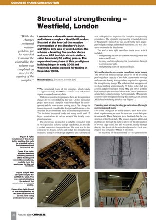
- 1. CONCRETE FRAME CONSTRUCTION Structural strengthening – Westfield, London “While the London has a dramatic new shopping staff, with previous experience in complex strengthening changes and leisure complex – Westfield London. procedures. The specialist engineering remedial division Situated at the heart of the massive of Structural Systems (UK) was asked by the client to pre- presented pare budget costings and method statements, and was cho- regeneration of the Shepherd’s Bush massive and White City area of west London, the sen to undertake the installation. problems for The works were split into three main areas, which scheme – boasting five anchor stores included: the remedial and over 265 top high street retailers • strengthening of slabs for column punching shear due team and the – also has nearly 50 eating places. The to increased loads client alike, the superstructure phase of this prestigious • forming and strengthening for penetrations through building began in early 2005 and post-tensioned slabs scheme was • strengthening slabs for increased loads. Westfield London opened for trading in completed on November 2008. time for the Strengthening to overcome punching shear issues This involved detailed design analysis of the existing opening of the punching shear capacity of the slabs, accurate site surveys complex.” RICHARD GASKILL, STRUCTURAL SYSTEMS (UK) and concrete density testing (where required) to optimise the strengthening design. The solution that was approved involved drilling approximately 30 holes in the slab per column and polyester resin fixing M12 and M16 × 200mm T he structural frame of the complex, which totals approximately 300,000m2, contains over 105,000m2 of post-tensioned concrete slabs. high-strength pre-tensioned shear bolts, on set perimeters around the existing columns. Approximately 100 concrete With most construction projects, there are always minor columns were strengthened using this method, with around changes to be expected along the way. On this particular 3000 shear bolts being installed (see Figure 1). project there was a change in both ownership of the devel- opment and the main tenants renting space. The change in Forming and strengthening penetrations through tenants required considerable design modifications to the post-tensioned slabs structure to accommodate their additional requirements. Due to the change in the main tenants, there were addi- This included increased loads and many small, and 17 tional requirements put upon the structure to suit their par- larger, penetrations to various areas of the already com- ticular needs. These, however, were finalised after the con- pleted structure. struction of the floor slabs. The tenants required additional The client was looking for a suitable contractor with penetrations through the slabs to allow for the introduction its own specialist in-house design capabilities, to provide of several large stairs, lifts and escalators, mainly through a fast but innovative design solution. The remit was for the three to four levels of the multi-level tenancies. Each pen- contractor to design, supply and install the strengthening etration was typically 1900mm × 4200mm. measures, using its own design expertise and experienced The majority of the additional service penetrations Figure 1 right: (Photos: Structural Systems (UK) Ltd.) Installation of the shear bolts, awaiting the nuts to be added before final alignment and tensioning up. Figure 2 far right: Exposed tendons following removal of the ducting and cementitious material, ready to form the anchorage for the cut tendons. Figure 3 right: FRP strengthening to the soffit of the slab. The core holes indicating the edge of the penetration are clearly visible. Figure 4 far right: Detail of the strengthening to the soffit in restricted access zone using embedded anchorage. 32 FEBRUARY 2009 CONCRETE
- 2. CONCRETE FRAME CONSTRUCTION were easily accommodated in the post-tensioned floors, due to the lack of complex reinforcement and the typical spacing of 1800mm for the post-tensioning tendons. The penetrations required a structural design review and the accurate pinpointing of the post-tensioned tendons, using a Ferro-scan initially, and then by drilling 20mm-diameter holes for exact positioning. Each tendon had to be fixed into position to lock the prestress into the strand. To form an anchorage for the strand, an area 600mm long × 300mm wide was broken out with the exposed tendon centralised longitudinally. Once the ducting and cementitious material had been removed, the strand was fixed using a BASF Masterflow 648CP Plus epoxy grout. From this point, the tendons could be cut to form the opening (see Figure 2). While the penetrations could be formed within the slab, there was still the issue of how the slab could be strength- ened around the penetration. FRP plates were bonded to the top and soffit of the slab, Figure 5: Example of a FRP plate anchored by using a mechanical anchoring device to around the perimeter of the openings. A layer of epoxy, provide a permanent fixing. 4mm in the middle of the plate and 2mm at the edges, was applied to the plate. The plates were then lifted into posi- tion and pushed into place with a rubber roller to expel the air from the epoxy, giving an overall thickness of 2mm (see Figure 3). FRP requires an anchor beyond the point that is required to span. Where access was limited due to beams or con- crete walls, 150mm embedded FRP plates were anchored into the beams or walls to provide a suitable anchorage (see Figure 4). At slab edges or around cores, it was not possible to provide a suitable anchorage, so a mechanical anchor was used, bonded to the underside of the FRP. Eight-millime- tre-thick plates were fixed to the concrete using 125mm embedded high-performance anchors (see Figure 5). The problem of strengthening around the faces of the penetration was efficiently dealt with by using Aramid FRP A120/420 wrap supplied by S & P, using a wet lay-up method. The 400gm/m2 sheets were presaturated by pass- ing them through a trough. The wet sheet was then applied using rollers. The final sheet was not applied until the first had sufficiently cured to support the other (see Figure 6). The use of FRP strips eliminated any problems with Figure 6: FRP being applied to the face of the opening. access and services that the more bulky structural steel strengthening solution would have raised. Strengthening for increased loads Significant change in use meant that in other areas, the original slabs did not have sufficient design load capac- ity to meet the new demands. The slabs therefore required a cost-effective strengthening solution, which provided minimal visual impact. FRP is extremely lightweight with excellent tensile strength properties and a plate thick- ness as low as 1.2mm. Having undertaken all the essen- tial design checks, it was necessary to increase the design capacity of the slabs to accommodate the additional load and also to overcome the excessive deflections (see Figure 7). After much analysis of suitable products in the market- place, an FRP solution was found to overcome the aesthetic limitations, while eliminating the excessive deflections. Concluding remarks While the changes presented massive problems for the remedial team and the client alike, the scheme was com- pleted on time for the opening of the complex. This was done using less materials as the design and system chosen proved to be far cheaper than the alternative options, offer- ing a saving of approximately 30% in the overall strength- ening costs. ■ Figure 7: Example of strengthening to the underside of the slab using unstressed FRP. CONCRETE FEBRUARY 2009 33