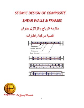
SEISMIC DESIGN OF COMPOSITE SHEAR WALLS & FRAMES - مقاومة الرياح والزلازل جدران قصية مركبة واطارات
•
11 likes•4,669 views

The document discusses different types of composite structural systems that combine steel and concrete elements. It describes composite slabs made with metal decking and concrete topping that act as diaphragms transferring shear forces. It also discusses composite girders that use shear stud connectors to increase the moment of inertia of the beam and girder, and composite columns with a steel core encased in concrete or steel tubes filled with concrete. The document emphasizes that composite systems allow for more efficient use of the dissimilar properties of steel and concrete in buildings.

Recommended
Recommended
More Related Content
What's hot
What's hot (20)
Similar to SEISMIC DESIGN OF COMPOSITE SHEAR WALLS & FRAMES - مقاومة الرياح والزلازل جدران قصية مركبة واطارات
Similar to SEISMIC DESIGN OF COMPOSITE SHEAR WALLS & FRAMES - مقاومة الرياح والزلازل جدران قصية مركبة واطارات (20)
More from Dr.Youssef Hammida
More from Dr.Youssef Hammida (20)
Recently uploaded
Recently uploaded (20)
SEISMIC DESIGN OF COMPOSITE SHEAR WALLS & FRAMES - مقاومة الرياح والزلازل جدران قصية مركبة واطارات
- 1. 1 Dr Youssef Hammida SEISMIC DESIGN OF COMPOSITE SHEAR WALLS & FRAMES ﺟدران واﻟزﻻزل اﻟرﯾﺎح ﻣﻘﺎوﻣﺔ ﻗﺻﯾﺔﻣرﻛﺑﺔواطﺎرات
- 2. 2 The structural system of a building is a complex three- dimensional assembly of interconnected discrete or continuous structural elements. The primary function of the structural system is to carry all the loads acting on the building effectively and safely to the foundation. The structural system is therefore expected to: Carry dynamic and static vertical loads. Carry horizontal loads due to wind and earthquake effects. Resist stresses caused by temperature and shrinkage effects. Resist external or internal blast and impact loads. Resist, and help damp vibrations and fatigue effects. steel-concrete composite systems for buildings are composed of concrete components that interact with structural steel components within the same system COMPOSITE ACTION BETWEEN STRUCTURAL ELEMENTS IN BUILDINGS Steel and concrete are the major materials used in composite systems. Although they have several dissimilar physical characteristics, it is possible to use them together, beneficially, in different ways. A number of systems have been developed in the last few decades which successfully combine steel and concrete. The following composite systems have been used for a wide range of buildings: اﻧﻮاعواﻟﺸﺎﻗﻮﻟﯿﺔ اﻷﻓﻘﯿﺔ ﻟﻠﺤﻤﻮﻻت اﻟﻤﺮﻛﺒﺔ اﻟﺠﻤﻞ
- 3. 3 1. Frame structure اﻻطﺎرات ﺟﻣﻠﺔ 2. Shear wall structure اﻟﻘص ﺣدران ﺟﻣﻠﺔ 3. Staggered shear wall system اﻟﻣ اﻟﻘص ﺟدرانﺗﻧﺎوﺑﺔ 4. Tubular system واﻻﻧﺑوﺑﯾﺔ اﻟﺷﺑﻛﯾﺔ اﻟﺟﻣل اﻟﻤﺮﻛﺒﺔ اﻷﺳﻘﻒ ﺑﻼطﺎت
- 4. 4
- 5. 5
- 6. 6
- 7. 7 اﻟﻤﺮﻛﺒﺔ واﻟﺒﻼطﺎت اﻟﺠﺎھﺰة اﻟﻤﻘﺎطﻊ
- 8. 8
- 9. 9 COMPOSITE MEMBERS اﻟﻣرﻛﺑﺔ اﻟﻣﺟﻣﻌﺔ اﻟﻌﻧﺎﺻر To get an idia into the composite behavior of structural steel and reinforced concrete systems, it is to study common techniques of compositing the following structural units: 1. Composite slabs واﻟطواق اﻷﺳﻘف ﺑﻼطﺎت 2. Composite beamsاﻟﻣرﻛﺑﺔ اﻟﻛﻣرات 3Composite columns اﻟﻣرﻛﺑﺔ ﻋﻣدة اﻷ 4. Composite diagonals اﻟﻣرﻛﺑﺔ اﻟﻣﺎﺋﻠﺔ اﻟﻘطرﯾﺔ اﻟﻌﻧﺎﺻر 5. Composite shear walls اﻟﻣرﻛﺑﺔ اﻟﻘص ﺟدران Composite slabs اﻟﻣرﻛﺑﺔ اﻟﺑﻼطﺎت In steel buildings, the use of high-strength, light-gauge (16–20 gauge) metal deck with concrete topping has become a standard (see Figure 2.1). The metal deck has embossments pressed into the sheet metal to achieve composite action with concrete slab. When the concrete hardens, the steel deck becomes the tension reinforcement. The resulting composite slab acts as a diaphragm providing for the horizontal transfer of shear forces to the vertical bracing elements. Furthermore, it actsas a stability bracing for the compression flange of steel beams.
- 10. 10 The shear forces in the diaphragm mostly occur in the concrete slab because the in-plane stiffness of concrete slab is significantly more than that of the metal deck. Thus, the horizontal forces must transfer from the slab to the beam top flange through welded studs اﻟﻘوىاﻻاﻟﺟﺳور اﻟﻰ اﻟﺑﻼطﺔ ﻣن ﺗﻧﺗﻘل واﻟزﻻزل اﻟرﯾﺎح ﻣن ﻓﻘﯾﺔ واﻟﻛﻣراواﻷﺳﺎس ﻋﻣدة اﻷ ﺛم اﻟﻘص ﺑﺳﺎﻣﯾر ﺑواﺳطﺔ ت ﻣﻘ ﻣﺳﺎﻣﯾر ﺗرﻛﯾباﻟﻛﻣرة ﺑﯾن اﻟواﺻﻠﺔ اﻟﻘص ﺎوﻣﺔ-واﻟﺑﻼطﺔ اﻟﺟﺳر
- 11. 11 اﻟﻘص وﻣﺳﺎﻣﯾر اﻟﺻﺎج اﻟواح ﺗرﻛﯾب
- 12. 12 Composite Girders اﻟﻣرﻛﺑﺔ اﻟﻛﻣرات -اﻟﺟﺳور Consider a typical steel moment frame consisting of beams rigidly connected to columns. Therefore, to limit the sway under lateral loads, it is more prudenteffecting to increase the girder stiffness rather than the column stiffness. Although frame beams are designed as non-composite, it is a usual practice to use shear studs at a nominal spacing of say, 12 in. The shear connectors primarily provided for the transfer of diaphragm shear also increase the moment of inertia of the girder. The increase, however, is not for the entire length of the girder because under lateral load sit bends in a reverse curvature. Since concrete is ineffective in tension, the increase in the moment of inertia can be counted on only in the positive moment region.
- 13. 13 ﺑﺎﻟﺧرﺳﺎﻧﺔ ﻣدﻓوﻧﺔ ﺗﻛون اﻟﻣرﻛﺑﺔ اﻟﻛﻣرات ﺻﻠﺑﺔ ﺗﻛون ان وﯾﺣب اﻟﺑﻼطﺔ اﺳﻔل ظﺎھرة او اﻟﺑﻼطﺔ ﻣﻊ اﺳﺎﺗﺎدھﺎ ﻧﻘﺎط ﻋﻧد ﻣﻌدﻧﻲ دك ﯾﺗواﺟد ﻗداﻟﺑﻼطﺔ اﺳﻔل اﻟﻣﻌدﻧﯾﺔ اﻟﻛﻣرة ﻣﻊ ﺳﻼب ﺳوﻟد او
- 14. 14
- 15. 15
- 16. 16 اﻟﻛﻣرات اﺳﺗﻧﺎد ﺗﻔﺎﺻل–اﻟﻔوﻻذﯾﺔ اﻷﻋﻣدة ﻣﻊ اﻟﺟﺳور
- 17. 17 اﻟﻘص ﺟدار ﻣﻊ اﻟﻣﻌدﻧﻲ اﻟﺟﺳر اﻟﻛﻣرة اﺗﺻﺎل ﺗﻔﺎﺻﺑلاﻟﺟدار ﻓﻲ ﻣﺛﺑﺗﺔ ﺑزواﯾﺎ
- 18. 18
- 20. 20 اﻟﺟﺳر ﻣﻊ اﻟﺷﺑﻛﻲ اﻟﺟﺎﺋز اﺗﺻﺎل-ﻛﻣرةﻣﺣﯾطﯾﺔﺧرﺳﺎﻧﺔ Composite Columns اﻟﻣرﻛﺑﺔ اﻷﻋﻣدة Two types of composite columns are used in buildings (see Figure 2.2a and b). The first, commonly referred to as encased composite column, consists of a steel core surrounded by a reinforced concrete envelope. The second referred to as filled composite column consists of a steel pipe or tube filled with high-strength concrete.
- 21. 21 In the first type, the steel core, most usually a wide flange section placed within the reinforced concrete column is designed as an erection column to carry construction loads only. Conceptually the behavior of a composite column is similar to a reinforced concrete column, if the steel section is analytically replaced with an equivalent mild steel reinforcement. In fact, this concept provides the basis for generating the interaction diagram for the axial load and moment capacities of composite columns. Compositing of exterior columns by encasing steel sections with concrete is by far the most frequent application of composite columns. The reasons are entirely economic, because forming around interior columns is quite involved and is not readily applicable to jump forms.
- 22. 22 Exterior columns, on the other hand, are relatively open-faced: formwork can be “folded” around steel columns for placement of concrete, then unfolded and jumped to the next floor.. ﻣﻌدﻧﻲ ﻋﻣودﻣرﻛباﻟﺧرﺳﺎن ﻓﻲ ﻣﻌدﻧﯾﺔ وﺗﺷﺎرﯾكة
- 23. 23 ﻣرﻛﺑﺔ اﻋﻣدة اﻟﻣﻌدﻧﻲ اﻟﺧﺎرﺟﻲ اﻟﻐﻼف
- 24. 24 اﻟﻣرﻛﺑﺔ اﻷﻋﻣدة اﺷﻛﺎلوﺗﺻﻣﯾم اﻻطﺎرات ﻣﻊ اﻟﺿﻌﯾف واﻟﺟﺎﺋز اﻟﻘوي اﻟﻌﺎﻣود
- 25. 25 اﻷﻋﻣدةﻟﻸﻋﻣدة اﻟﺷﺎﺋﻌﺔ اﻷﻧﻣﺎ اﺣد ﻫﻲ اﻟﻣﻐﻠﻔﺔ ﺔ اﻟﻔوﻻذﺔ اﻟﻣر.ﺔ اﻟﺻﻼ ﺑﯾن ﯾﺟﻣﻊ اﻟﻧظﺎم ﻫذا وﻗﺎﺑﻠﺔاﻹﻧﺷﺎﺋﻲ ﻟﻠﻔوﻻذ اﻹﻧﺷﺎء ﻋﺔوﺳر اﻟﻘوة ﯾن و اﻟﻣﺳﻠﺣﺔ ﻟﻠﺧرﺳﺎﻧﺔ ﯾﻞ اﻟﺗﺷ ﻟﻠوﺻولاﻟﻰﻣﻧﺷﺄاﻗﺗﺻﺎدوﻣﻘﺎوم
- 27. 27
- 28. 28
- 29. 29 ﺗﺻﻣﯾماﻟﻣرﻧﺔ اﻟطرﯾﻘﺔ اﻟﻣرﻛﺑﺔ اﻷﻋﻣدة
- 30. 30
- 31. 31 اﻣرﯾﻛﻲ ﻛود اﻟﻣرﻛﺑﺔ اﻷﻋﻣدة ﺗﺻﻣﯾم
- 32. 32
- 33. 33
- 34. 34 ااﺗﺟﺎھﯾن اﻧﻌطﺎف ﻋزم ﻣرﻛﺑﺔ ﻋﻣدةﻋﻠﻰﻣﺣورﯾن
- 35. 35
- 36. 36
- 37. 37 اﻵﺑﺎك ﻣﺧطط ﻣن اﻟﻣرﻛب اﻟﻌﺎﻣود ﺗﺻﻣﯾمﺑﺎﺗﺟﺎھﯾن ﻋزم
- 38. 38
- 39. 39
- 40. 40 Composite diaGonals اﻟﻣرﻛب اﻟﻣﺎﺋل اﻟﻘطري اﻟﻌﻧﺻر As a part of a vertical truss, diagonals in a braced frame resist lateral forces primarily through axial stresses. As a result, braced frames are more economical than moment-resisting frames. However,their use is often limited, because of potential interference with architectural planning concerns
- 41. 41 FIGURE 2.3 Japanese composite construction details: (a) beam column intersection; (b and c) composite column with welded ties; ﻣرﻛب اطﺎر ﻋﻘدة ﺗﻔﺻﯾلﻟﻠﻌزوم ﻣﻘﺎوم
- 42. 42 Composite shear Walls اﻟﻣرﻛﺑﺔ اﻟﻘﺻﯾﺔ اﻟﺟدران One of the most common uses of composite shear walls is in steel frame buildings, in which selected bays are infilled with a reinforced concrete wall. In essence, this results in a reinforced concrete shear wall with structural steel boundary elements and coupling beams (see Figure 2.5). ااﻟﻣﻌدﻧﻲ اﻷﺑﻧﯾﺔ ﻓﻲ اﻟﻣرﻛﺑﺔ اﻟﻘﺻﯾﺔ اﻟﺟدران ﺳﺗﻌﻣﺎلة If the coupling beams were pin-connected at each end to the boundary elements, they would be ineffective in improving the lateral resistance of the wall. This is because the two wall piers would resist lateral loads independently. On the other hand, if the coupling beams are infinitely stiff, they would fully couple the two piers coercing them to work as a single unit. If the coupling beam stiffness is in between the two extremes, as is the case in most buildings, the corresponding response will also be in between the two limits. Composite steel plate diaphragms are appropriate when extremely high shear forces must be transferred from one system to another at the base of the building. An example of this use may be found again in the Bank of China Tower, Hong Kong, in which the entire
- 43. 43 base shear is transferred from the building perimeter to the building core at the base, via a steel-plated floor diaphragm. Possible details of composite shear plate walls are shown in Figure 2.6. In these details, structural steel framing surrounds the steel plates with the entire steel assembly encased in reinforced ﻟﻠﻌزوم ﻣﻘﺎوﻣﺔ ﺳﺗﯾل ﻓوﻻذﯾﺔ ﻣﻌدﻧﯾﺔ اطﺎرات ﺿﻣن ﻣرﻛﺑﺔ اﻋﻣدة اﺳﺗﻌﻣﺎل
- 44. 44 ﺟداروﺟ ﻋﻠﻰ ﻓوﻻذﯾﺔ ﺑﺻﻔﺎﺋﺢ ﻣرﻛب ﻗﺻﻲووﺟﮭﻲ واﺣد ﮫن
- 45. 45 اﻟﻧﮭﺎﯾﺎت ﻓﻲ اﻟﻣطﺎوﻋﺔ زﯾﺎدة اﻋﻣدة ﻣﻊ ﻣرﻛب ﻗﺻﻲ ﺟدارواﻟوﺳط اﻟﻘص ﺗﺷﺎرﯾك ﻟﺣﺎم
- 46. 46 اﻓوﻻذي ﺑروﻓﯾل ﻣﻊ ﻣرﻛﺑﺔ اﻟﻘﺻﻲ اﻟﺟدار ﻧﮭﺎﯾﺎت ﻋﻣدة
- 47. 47 جﻓوﻻذﯾﺔ ﻛﻣرة ﻣﻊ ﻣرﻛب ﻗﺻﻲ داراﻟﻠدن اﻟﻣﻔﺻل وﺗﺷﻛل coupling Beam
- 48. 48 اﻟﻣﺳﻠﺣﺔ اﻟﺧرﺳﺎﻧﺔ ﻣﻊ ﻣدﻓوﻧﺔ ﻓوﻻذﯾﺔ ﺑروﻓﯾﻼت ﻣﻊ اﻟﻣرﻛﺑﺔ اﻟﻘﺻﯾﺔ اﻟﺟدران The concrete advantages in terms of higher stiffness, good fire protection, buckling prevention, recommends composite elements made by steel and concrete to be used in high-rise buildings placed in seismic areas. The steel concrete composite shear walls are used as lateral loads resisting systems for high-rise buildings as an alternative to reinforced concrete shear walls. Composite steel concrete shear walls are structural walls where at the boundary elements of the wall are encased steel profiles. واﺑﻧﯾﺔ اﻟﺧرﺳﺎﻧﺔ اﺑﻧﯾﺔ ﻣﻊ اﻟﻣرﻛﺑﺔ اﻟﻘﺻﯾﺔ اﻟﺟدران ﺗﺳﺗﻌﻣل ﺑﺎﻻﺿﺎﻓ ﺷﺎﻗوﻟﯾﺔ ﺣﻣوﻻت ﻟﻣﻘﺎوﻣﺔ اﻟوﻗت ﺑﻧﻔس ﻓوﻻذﯾﺔﺔ واﻟزﻻزل اﻟرﯾﺎح ﻟﺣﻣوﻻت Composite Shear Walls with Encased Profiles
- 49. 49 ﻣﺣﺎط ﻣﺳﻠﺣﺔ ﺧرﺳﺎﻧﺔ ﻣرﻛب ﻗﺻﻲ ﺟدرارﻓوﻻذ ﺑروﻓﯾلي ﻗﺻﯾﺔ وﺻل وﺑﺳﺎﻣﯾر
- 50. 50 اﻟﻔوﻻذي اﻟﺑروﻓﯾل اﻧواع ﻣﻊ ﻣرﻛﺑﺔ ﻗﺻﯾﺔ ﺧرﺳﺎﻧﺔ ﺟدران اﺷﻛﺎل ﺗﻔﺎﺻﯾل
- 51. 51 اﻟﻣرﻛﺑﺔ اﻟﻣﺳﻠﺣﺔ اﻟﺧرﺳﺎﻧﺔ ﺟدران واﺷﻛﺎل اﻧواع اﻟﻣﻌدﻧﻲ واﻟﺑروﻓﯾل اﻟﺻﻔﺎﺋﺢ وﺗﻣوﺿﻊ
- 52. 52 اﻟﺻﻧﻊ ﻣﺳﯾﻘﺔ اﻟﻣرﻛﺑﺔ اﻟﻘﺻﯾﺔ اﻟﺟدران
- 53. 53
- 54. 54 اﻟﺻﻧﻊ وﻣﺳﺑﻘﺔ اﻟﻣرﻛﺑﺔ اﻟﻘﺻﯾﺔ اﻟﺣدران ﺿﻣنﻟﻠﻌزو ﻣﻘﺎوﻣﺔ ﺧﺎﺻﺔ ﻓوﻻذﯾﺔ اطﺎراتم
- 55. 55 واﻟﻔوﻻذﯾﺔ اﻟﺧرﺳﺎﻧﯾﺔ اﻟﻣرﻛﺑﺔ اﻟﺣدران اﺗﺻﺎل ﺗﻔﺎﺻﯾل اﻟﻔوﻻذي اﻟﺑروﻓﯾل ﻣن اﻟﻧﮭﻠﯾﺎت ﻋﻧﺎﺻر ﻣﻊ
- 56. 56 Composite shear wall assembly could speed construction of steel frames The sandwich, called a dual-plate composite shear wall because its steel-plate walls are filled with lightly reinforced concrete, is not for use only in seismic zones. “It is a great system for multihazard mitigation because it is good for seismic, wind and gravity loads as well as blast resistance, ”ﺧﺎرﺟﯾﺔ ﻓوﻻذﯾﺔ ﺻﻔﺎﺋﺢ ﺑروﻓﯾل اﻟﻣرﻛب اﻟﻘﺻﻲ اﻟﺟدار ﻣﺳﻠﺣﺔ وﺧرﺳﺎﻧﺔ
- 57. 57 COMPOSITE SUBSYSTEMS These systems may be categorized as follows: واﻟﻣرﻛﺑﺔ اﻟﻔوﻻذﯾﺔ اﻟﻘﺻﯾﺔ اﻟﺟﻣل اﻧواع 1. Composite moment frames 2. Composite braced frames 3. Composite eccentrically braced frames 4. Composite shear wall-frame interacting systems 5. Composite tube systems 6. Vertically mixed systems 7. Mega frames with super columns 8. High-efficiency structures Composite moment Framesمﻟﻠﻌزو اﻟﻣﻘﺎوﻣﺔ اﻟﺧﺎﺻﺔ اﻟﻣرﻛﺑﺔ اﻻطﺎرات Refer to Figure 2.9 for schematics of a composite moment frame consisting of steel beams and composite columns. The columns may consist of either concrete encased or filled composite columns, with moment connected steel beams.
- 58. 58 ﻣرﻛﺑﺔ واﻋﻣدة ﻟﻠﻌزوم ﻣﻘﺎوﻣﺔ ﺧﺎﺻﺔ ﻓوﻻذﯾﺔ اطﺎرات اﻟﺿﻌﯾف واﻟﺟﺎﺋز اﻟﻘوي اﻟﻌﺎﻣود وﺗﺣﻘﯾﻖ Intermediate and special moment frames must satisfy detailing requirements that are more stringent than those for ordinary moment frames The reason is to assure a ductile response when these buildings are pushed beyond elastic limit in a major seismic even
- 59. 59 ﻣرﻛب وﻋﺎﻣود ﻓوﻻذﯾﺔ ﻛﻣرات و ﻟﻠﻌزوم ﻣﻘﺎوﻣﺔ اﻧﺻﺎل ﻋﻘدة اﻟﻘوي اﻟﻌﺎﻣود ﺗﺣﻘﺑﻖ
- 60. 60 Seismic provisions of AISC 341-05 recognize three types of composite moment frames: 1. Ordinary moment frames 2. Intermediate moment frames 3. Special moment frames اﻻطﺎرات واﻧواع اﻷﻣرﯾﻛﻲ اﻟﻛوداﻟﻣرﻛﺑﺔﻟﻠﻌزوم اﻟﻣﻘﺎوﻣﺔ Special Moment Frames- ةاﻟﺧﺎص اﻟﻣرﻛﺑﺔ اﻻطﺎرات The term “special” refers to the characteristics of the frame in which the members and connections are designed and detailed to provide maximum ductility and toughness, implying excellent energy dissipation and seismic performance during severe earthquake shaking. In recognition of the ductility, seismic provisions allow a maximum reduction in the design base shear. Because of the recognized ductility and the limited interference with architectural planning, special moment frames are one of the most commonly used lateral systems. اﻻط اﺷﺗراطﺎت ﻧﻔس ﺗطﺑﻖﺎواﻟﺧرﺳﺎﻧﯾﺔ اﻟﻔوﻻذﯾﺔ راتاﻟﻣرﻛﺑﺔ اﻻطﺎرات ﻋﻠﻰ اﻟﻠدن اﻟﻣﻔﺻل وﺗﺷﻛل اﻟﻣطﺎوﻋﺔ ﺣﯾث ﻣن
- 61. 61 اﻟﺿﻌﯾف واﻟﺟﺎﺋز اﻟﻘوي اﻟﻌﺎﻣود وﻗﺎﻋدة اﻟﻣطﺎوﻋﺔ ﻋﺎﻣل وﯾؤﺧذRاﻟﺟداول ﻣن اﻟﻣﻘﺎوﻣﺔ زﯾﺎدة او Composite special moment frames are similar in configuration to ordinary moment-resisting frames. As in steel or concrete systems, more stringent detailing provisions are required to increase the system’s ductility and toughness. The commensurate reduction in design lateral force is very similar to that in steel or concrete special moment frames. The design intent is to confine inelastic hinging in beams, while the columns and connections remain essentially elastic. The design base shear prescribed for this system is similar to the special moment-resisting frame systems of steel or reinforced concrete. Likewise, no limitations have been placed on their usage in buildings assigned to a higher SDC. special moment-resting frames attempts to provide the maximum possible frame ductility, toughness, and energy-dissipation capacity. This requirement results in more stringent provisions for member and joint detailing. Generally these frames are designed to limit inelastic action to the beams, with the intent of preventing potential yielding in columns and connections.
- 62. 62 The design should include the strong column-weak beam concept. For composite columns, transverse reinforcement requirements should be equivalent to those required for reinforced concrete columns in special moment-resisting frames. Special details are required to satisfy closed-hoop and cross-tie requirements for encased composite columns. ﻗﻲ اﻟﻣطﺎوﻋﺔ ﻟزﯾﺎدة ﺧﺎﺻﺔ ﺗرﺗﯾﺑﺎتاﻋﻣدةاﻟﻣرﻛﺑﺔ اﻻطﺎرات and lateral torsional buckling, allowing the beams to develop their full plastic flexural capacity. However, steel flanges connected to concrete slabs with shear connectors are exempted from this provision. This is because lateral torsion and local buckling are inhibited by the shear connectors and concrete slab.
- 63. 63 he design of composite frames is not significantly different from the procedures for structural steel or reinforced concrete moment frames اﻻط وﻣﻣطوﻟﯾﺔ ﻣطﺎوﻋﺔﺎاﻟﻣرﻛﺑﺔ اﻟﺧﺎﺻﺔ رات Encased composite columns should have a minimum ratio of structural steel gross column area of 4%. The shear strength of columns generally ignores the contribution of concrete. However, the contribution of the shear strength of the reinforcing ties based on an effective shear width bf of the section, as noted in Figure 2.12, is permitted. For filled composite columns; it is conservative to neglect the contribution of concrete to the shear strength of the column.
- 64. 64 Where shear strength becomes critical, the composite column may be treated as a reinforced concrete column with the steel considered as shear einforcement. Transfer of forces between structural steel and reinforced concrete should be made through shear connectors, ignoring the contribution of bond or friction. ﻓﻲ ﻟﻠﻘص اﻟﺧرﺳﺎﻧﺔ ﻣﻘﺎوﻣﺔ ﻻﺗؤﺧذاﻟﻣﺗﺷﻘﻖ اﻟﻣﻘطﻊ اﻟﻠدن اﻟﻣﻔﺻل ﺗﺷﻛل وﻣﻧطﻘﺔ
- 65. 65 Composite Braced Framesاﻟﻣرﻛﺑﺔ واﻟﻘطرﯾﺔ اﻟﻣﺎﺋﻠﺔ اﻟدﻋم ﻋﻧﺎﺻر two types of composite braced frames are recognized in AISC 341- 05/10: (1) Concentric bracing, where various bracing members meet at a common point; and (2) a relatively new form of braced frame called eccentric brace. this system combines the ductility of moment frames with the high stiffness of concentrically braced frames ﻋﻧﺎﺻرواﻟﻘ اﻟﻣﺎﺋﻠﺔ اﻟدﻋماﻟﻔوﻻذﯾﺔ طرﯾﺔ اﻟﻣرﻛﺑﺔ واﻷﻋﻣدة
- 66. 66 Composite brace design in concentrically braced frames must recognize that these elements are expected to provide for the inelastic action during large seismic overloads. Braces consisting of concrete encased steel elements should include reinforcing and confinement steel sufficient to provide the intended stiffening effect even after the brace has buckled during multiple cycles of seismic motion. As a result, it is recommended that these elements should meet detailing requirements similar to those for composite columns. Composite braces in tension should be designed considering the resistance provided only by the steel. اﻟﻣﺎﺋل اﻟﺗدﻋﯾم ﺣﺎﻻت ﺟﻣﯾﻊاﻟﺧرﺳﺎﻧﺔ اﻟﻣرﻛب اﻟﺷد ﻓوى ﻣﻘﺎوﻣﺔ ﻓﻲ ﺗﺷﺎرك ﻻ-اﻟﻠدن اﻟﻣﻔﺻل ﺗﺷﻛل ﻣﻧﺎطﻖ ﻓﻲ ﺗواﺟدھﺎ ﻋﻧد اﻻﻧﺗﺑﺎه وﯾﺟب اﻟﻠدوﻧﺔ ﻣﺟﺎل ﻓﻲ واﻟﻌﻣل
- 67. 67 Brace buckling and the resulting large rotation demands at the brace ends should be considered in connection detailing. Schematic details of brace to encased composite column are shown in Figure 2.14a and b.
- 68. 68 Composite Eccentrically Braced Frames اﻟﻼ اﻟﻣرﻛﺑﺔ اﻟﻣﺎﺋﻠﺔ اﻻطﺎرات ﻋﻧﺎﺻرﻣرﻛزﯾﺔ figure 2.15. In general, beams in composite eccentrically braced frames consist of structural steel sections. Any concrete encasement of the beam should not extend into the link regions where large inelastic action is expected to develop (see Figure 2.16a). Columns and braces can be of either structural steel or composite construction. The analysis, design, and detailing of the system is similar to that for steel eccentrically braced frames since the force transfer mechanisms between the steel and concrete rely on bearing and shear friction, special attention must be paid to the design of connections to realize the intended inelastic action intheductile links
- 69. 69 . ﻣرﻛزﯾﺔ اﻟﻼ اﻟﻣﺎﺋﻠﺔ اﻟدﻋم ﻋﻧﺎﺻر
- 70. 70 Composite brace design in eccentrically braced frames must recognize that these members are intended to remain essentially elastic during large seismic overloads. The design strength must consider the yielding and significant strain hardening that can occur in properly designed and detailed link elements. Both axial and bending forces generated in the braces by the strain-hardened linkاﻟﻣرﻧﺔ اﻟﻣﻧطﻘﺔ ﺿﻣن ﻋﻣﻠﮭﺎ ﯾﺑﻘﻰ واﻟﻘطرﯾﺔ اﻟﻣﺎﺋﻠﺔ اﻟدﻋم ﻋﻧﺎﺻر وﻣﻧطﻘﺔ اﻟﻌﺎﻣود ﻣﺣورﻋﻘدة ﻋن ﺑﻌﯾد اﺗﺻﺎﻟﮭﺎ وﯾﺑﻘﻰ ﻟدﻧﺔ ﻣﻔﺎﺻل ﻓﯾﮭﺎ وﻻﯾﺗﺷﻛل ﺗﺷﻛاﻟﺷﻛل ﻓﻲ ﻛﻣﺎ اﻟﻠدن اﻟﻣﻔﺻل ل
- 71. 71 beams must be considered. اﻟﻠد اﻟﻣﻔﺻل ﺗﺷﻛل ﻋن ﺑﻌﯾدة وﻧﻘﺎط اﻣﺎﻛن ﻓﻲ واﻟﻣﺎﺋﻠﺔ اﻟﻘطرﯾﺔ اﻟﻌﻧﺎﺻر وﺻلن
- 72. 72 Reinforced Concrete Core With steel surrounding واﻟﻣرﻛﺑﺔ اﻟﻔوﻻذﯾﺔ واﻻطﺎرات اﻟﺧرﺳﺎﻧﻲ اﻟﻛور ذات اﻷﺑﻧﯾﺔ Core walls enclosing building services such as elevators, mechanical and electric rooms, and stairs have been used extensively to resist lateral loads in tall concrete buildings. The use of simple shapes such as C and I shaped walls around elevators interconnected with coupling beams constitutes one of the most typical methods of providing resistance to lateral loads. In the composite version of this system, a central concrete shear wall core is designed to resist the entire lateral load while the remainder of framing surrounding the core is designed for gravity loads using structural steel, metal deck and concrete topping (see Figure 2.18) concrete core is built first, using jump or slip forms, followed by erection of steel surround, as shown in Figure 2.19. Although structural steel erection may not proceed as fast as in a conventional steel building, the overall construction time is likely to be less because the building’s vertical transportation, consisting of stairs and elevators and mechanical and electrical services can be installed with in the core while erection of steel outside of the core is still in progress The only nonstandard connection is between shear walls and floor beams.
- 73. 73 Various techniques have been developed for this connection, chief among them, are the embedded plate and pocket details, as shown in Figure 2.20. The floor construction invariably consists of composite metal deck with concrete topping The floor within the core may be constructed either in concrete or structural steel. The connection between the floor slab and core walls is often project specific. ﻣﺳﻠﺣﺔ ﺧرﺳﺎﻧﺔ ﺟدران ﯾﻛون ان ﻟﻠﻛور ﯾﻣﻛنﻓوﻻذي ﺑروﻓﯾل او The weld plate detail shown in Figure 2.20a is, however, the most popular, particularly in a slip-formed construction.
- 74. 74 The weld plates are set with the outer surface flush with the wall surface. The plate is anchored to the wall by shear connectors welded to the plate. ﻣﺳﻠﺣﺔ ﺧرﺳﺎﻧﺔ ﺟدران ﻣﻊ اﻟﻔوﻻذﯾﺔ اﻟﻛﻣرات اﻧﺻﺎل ﻣﺛ ﻗوﻻدﯾﺔ ﺻﻔﺎﺋﺢ ﺑواﺳطﺔﺑاﻟﺣﺟرﻟن ﻓﻲ ﺑراﻏﻲ ﻣﻊ ﺗﺔ
- 75. 75
- 76. 76 shear Wall-Frame interactinG systems This system has applications in buildings that do not have sufficiently large cores to resist the entire lateral loads. This may require interaction of shear walls with moment frames to supplement the lateral stiffness of the shear cor واﻟﺟدراﻧ اﻻطﺎرات ﺑﯾت اﻟﺗﻔﺎﻋﻠﻲ اﻟﻧظﺎم ﺟﻣﻠﺔاﻟﻘﺻﯾﺔ ﺎ
- 77. 77 Composite tube systems اﻻﻧﺑوﺑﯾﺔ اﻻطﺎرات ﺟﻣﻠﺔ The key to the success of tube construction as noted earlier, lies in the rigidity of closely spaced exterior composite columns and deep spandrels. This results in an exterior façade that behaves more like a bearing wall than as a moment frame.
- 78. 78 VertiCally mixed systems اﻟﺟﻣلاﻟﻔﺻﯾﺔاﻟﻣﺧﺗﻠطة Mixed-use buildings are thos e that provide for two or more types of occupancies in a single building.
- 79. 79 For example, lower levels of the building may be for parking; middle levels for office floors; and the top levels for residential units, such as apartments and hotel rooms. Therefore, it makes economical sense to stack up different systems vertically up the building height using a system that is most logical for the particular occupancy. For example, beamless flat ceilings with a minimum of floor-to-floor height are preferred in residential occupancies
- 80. 80 ﺳﻔﻠﯾﯨﺔ طواﺑﻖ ﺧرﺳﺎﻧﺔ ﺟدران ﻛور اﻋﻠﻰ ﻓوﻻذﯾﺔ ﺳﺗﯾل ﺟدران ﻛور
- 81. 81 meGa Frames With super Columns اﻟﻛﺑﯾر اﻟﻌﻣﻼق اﻟﻣرﻛب اﻟﻌﺎﻣودواﻟﺷﺎﻗوﻟﯾﺔ اﻷﻓﻘﯾﺔ اﻟﻘوى ﻣﻘﺎوﻣﺔ ﺷﺑﻛﯾﺔ ﯾﺟواﺋزﻣﺣﯾطﯾﺔ واﺣزﻣﺔ One of the methods resisting lateral loads in tall buildings to provide big columns placed as far as possible at the perimeter of building, and interconnect the columns with a shear-resisting system such as Vierendeel frames, or super diagonals. The construction of super columns can take on many forms system uses large-diameter steel pipes filled with high-strength concrete. Generally, neither longitudinal nor transverse reinforcement is used in the columns,. Another method to encase steel columns using conventional forming techniques.
- 82. 82
- 83. 83 ﻓوﻻذي ﻋﺎﻣود ﻣﻊ ﻣرﻛب ﺟﺎﺋز اﺗﺻﺎل ﺗﻔﺎﺻﯾل
- 84. 84 (A) Plastic stress distribution for negative moment: (a) composite beam section; (b) plastic neutral axis, PNA, in steel beam web; (c) PNA in beam flange. (B) Plastic stress distribution for positive moment: (a) plastic neutral axis, PNA, in concrete slab; (b) PNA in steel beam flange; (c) PNA in steel beam web.
- 85. 85 AISC Design encased composIte columns Limitations اﻟﻣرﻛﺑﺔ اﻷﻋﻣدة وﺗﺻﻣﯾم اﻷﻣرﯾﻛﻲ ﻟﻛودا To qualify as an encased composite column, the following limitations shall be met: 1. The cross-sectional area of the steel core shall comprise at least 1% of the total composite cross section. 2. Concrete encasement of the steel core shall be reinforced with continuous longitudinal bars and lateral ties or spirals. 3.The minimum transverse reinforcement shall be at least 0.009 in.2 per in. of tie spacing
- 86. 86
- 87. 87
- 88. 88
- 89. 89
- 90. 90
- 91. 91
- 92. 92 اﻟﻣﺑﺎﻧﻲ وﺗﺻﻣﯾم اﻷورﺑﻲ اﻟﻛودو اﻟﻔوﻻذﯾﺔاﻟﻣرﻛﺑﺔ TYPES OF CROSS-SECTION FOR COMPOSITE COLUMNS AND THEIR ADVANTAGES Figure 1 shows typical cross-sections of composite columns together with the dimensional notation used in Eurocode 4 [1]. The sections can be classified into two groups: concrete filled sections in which the concrete is hidden totally and partly encased sections. Eurocode 8 rules on steel & composite structures
- 93. 93
- 94. 94
- 95. 95
- 96. 96
- 97. 97
- 98. 98
- 99. 99
- 100. 100
- 101. 101
- 102. 102
- 103. 103
- 104. 104
- 105. 105
- 106. 106
- 107. 107
- 108. 108
- 109. 109
- 110. 110
- 111. 111 Establishing Earthquake Loads for Composite Shear Walls Using US Codes اﻟﺣﻣوﻻت ﻣن اﻟزﻻزل ﺣﻣوﻟﺔ ﻣﻌﺎدﻟﺔ ﺣﺳﺑﺎب
- 112. 112 ﻣرﻛﺑﺔ ﻗﺻﯾﺔ ﺟدران اﺟل ﻣن اﻟزﻻزل ﻗوة ﺣﺳﺎب
- 113. 113 اﻟﻣطﺎوﻋﺔ ﻋﺎﻣل اﺳﺗﻌﻣﺎل ﺟدولRاﻟﻣﻘﺎوﻣﺔ زﯾﺎدة
- 114. 114 ااﻟﻣﺳﻣوح اﻟﻣروﻧﺔ ﺣد ﺟﮭﺎد
- 115. 115 Design of Composite Wall Element ﺗواﺟداﻟﻣﺳﻣوح واﻟﻘص اﻟدﻋﻣﺔ
- 116. 116 اﻟﻣرﻛب اﻟﻘص ﺟدار ﺣول اﻟﻛود اﺷﺗراط
- 117. 117 اﻻﻧﻘﻼب وﻋزم اﻟﻘﺎﻋدي اﻟﻘص ﺗﺻﻣﯾم
- 118. 118 اﻟﻛﻣرة ﻣﻊ اﻟﻣﻌدﻧﯾﺔ اﻟﺻﻔﯾﺣﺔ اﻧﺻﺎلواﻟﻌﺎﻣود
- 119. 119 واﻟﻌﺎﻣود اﻟﻛﻣرة ﻣن اﻻطﺎر ﺗﺻﻣﯾم
- 120. 120 واﻟﺟﻧﺎح اﻟﺟﺳد وﺗﺣﻧﯾب اﻟﻣﺳﻣوﺣﺔ اﻻﺟﮭدات
- 121. 121 ﻧﻓﻲ اﻟﻣرﻛب اﻟﻘﺻﻲ اﻟﺟدار ﻣذﺟﺔﺑرﻧﺎﻣﺞاﻟﺣﺎﺳب
- 122. 122