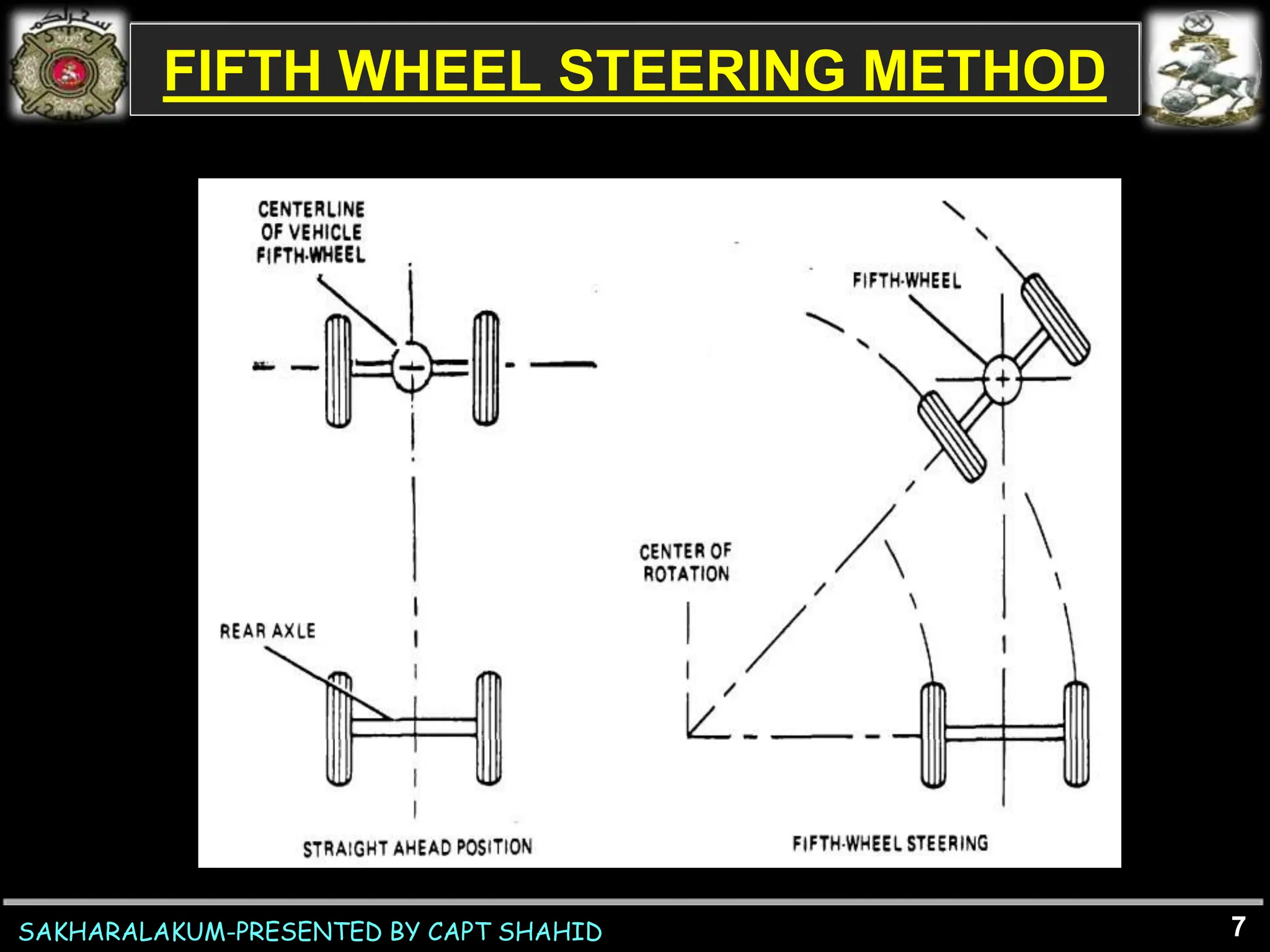
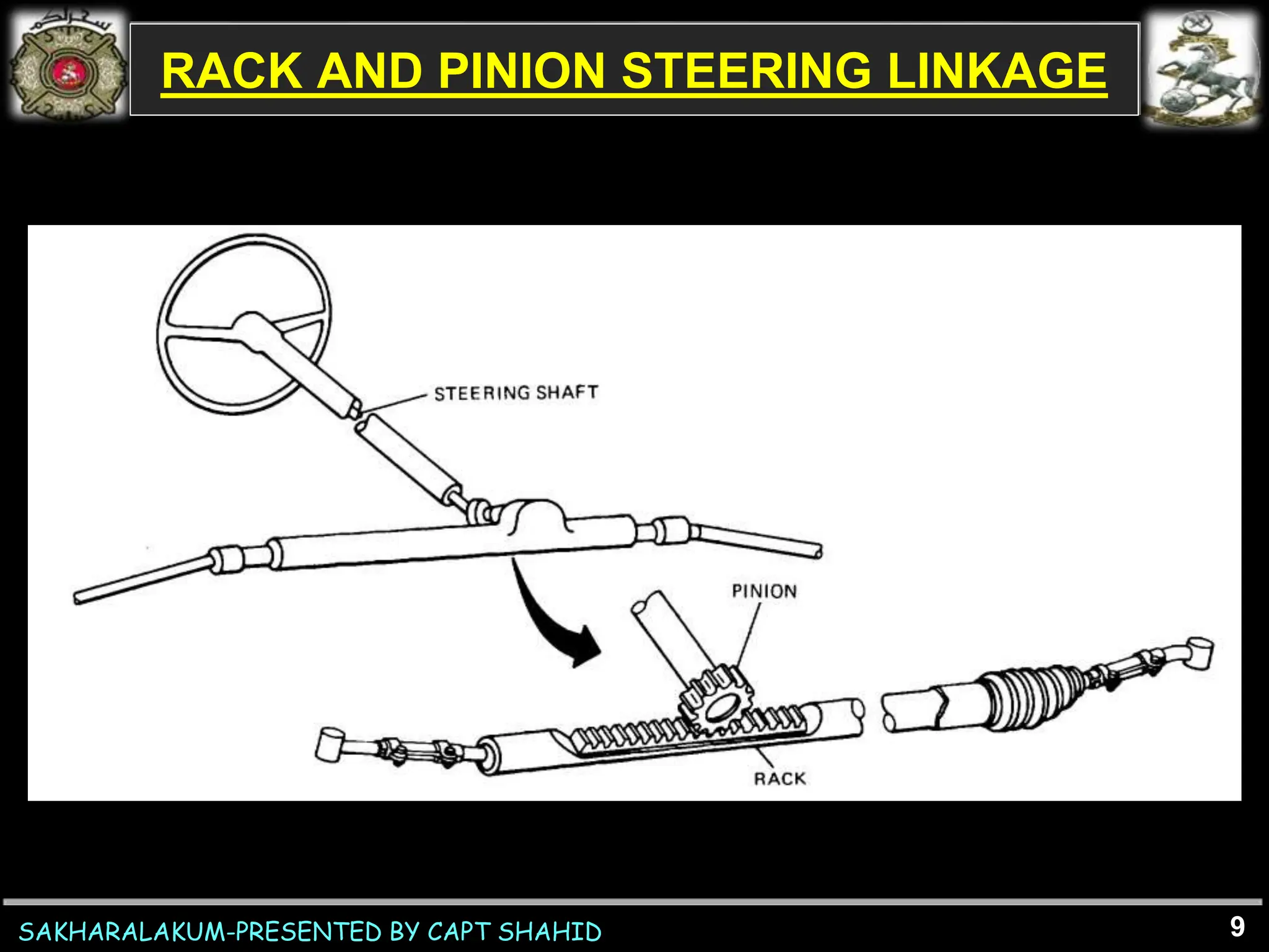
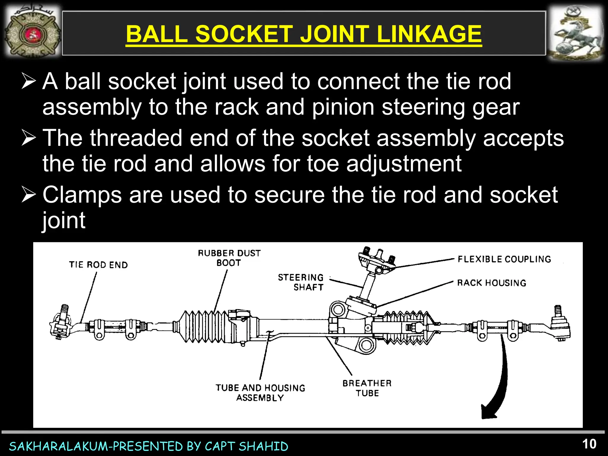
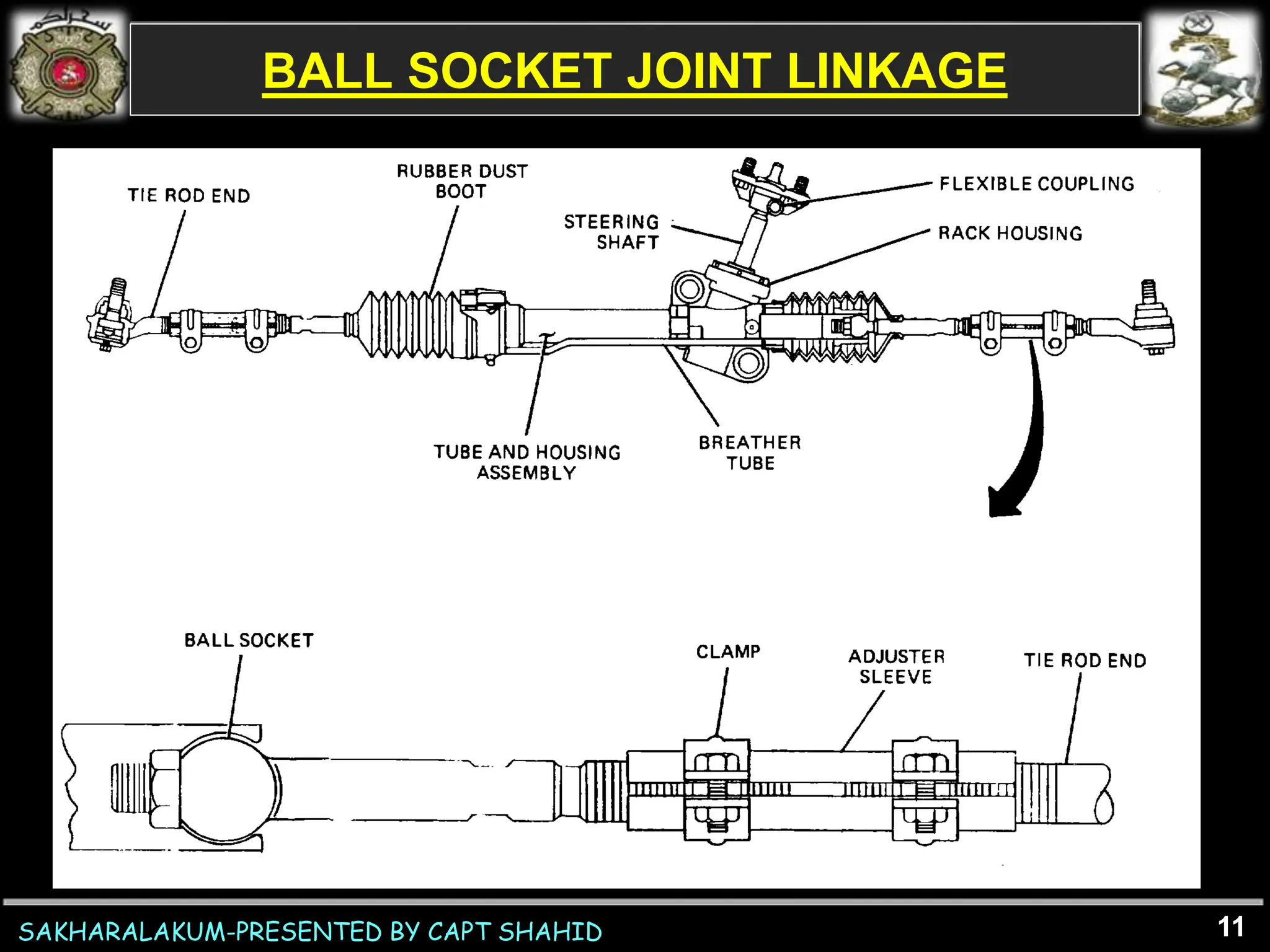
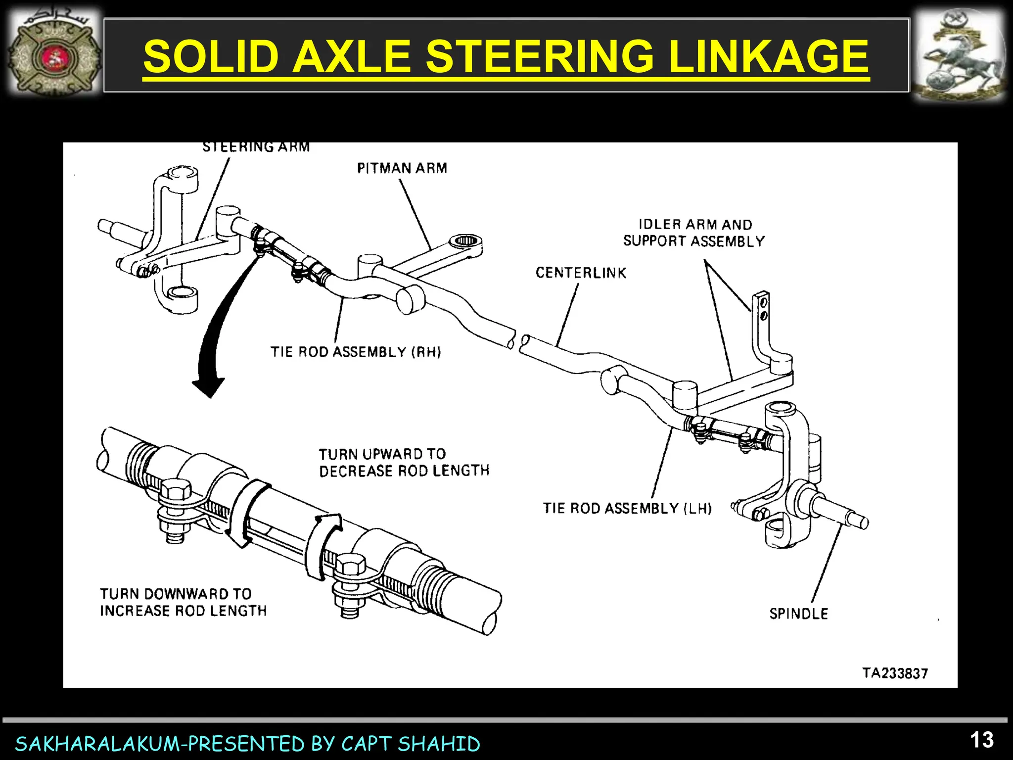
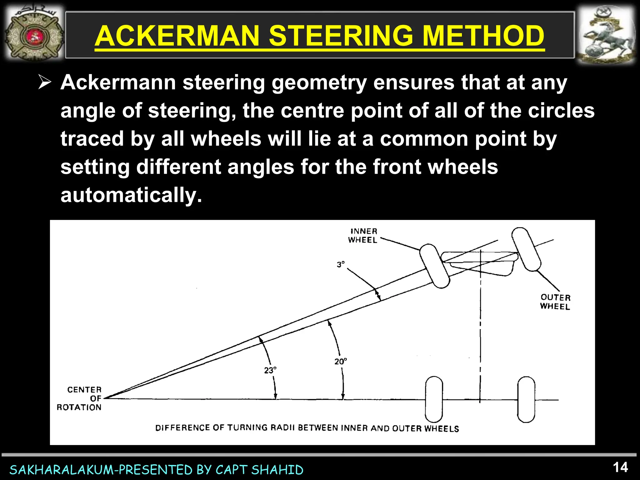
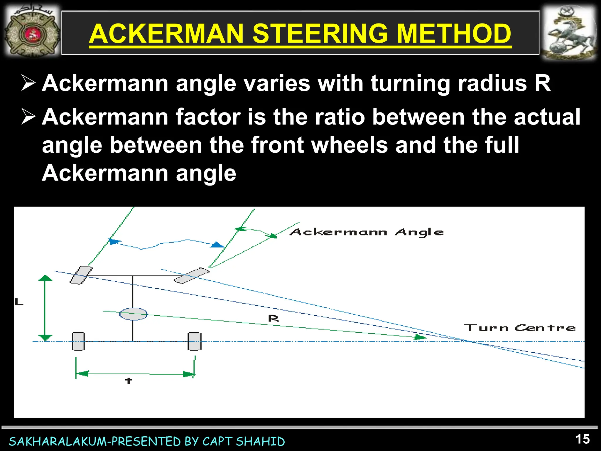
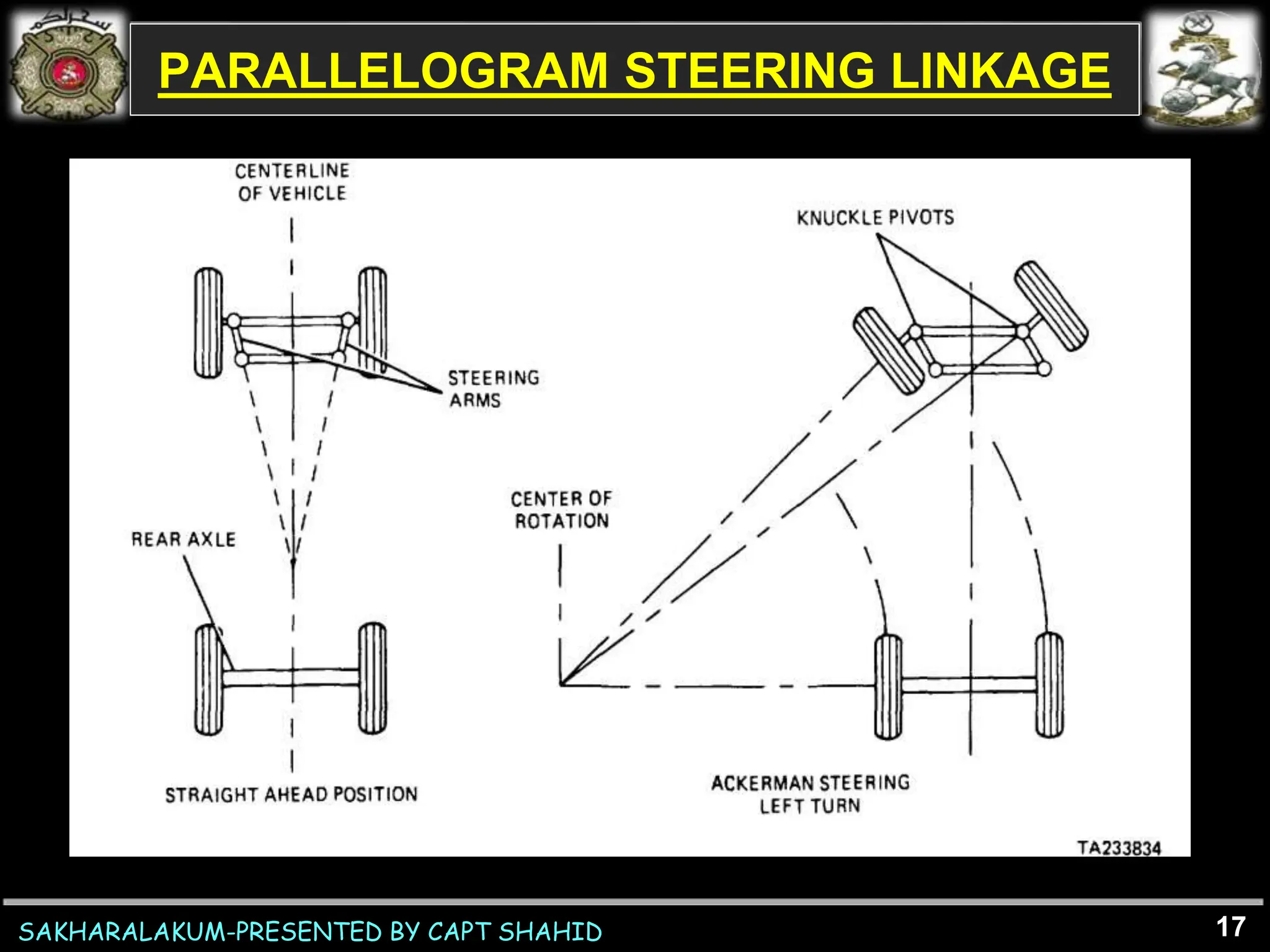
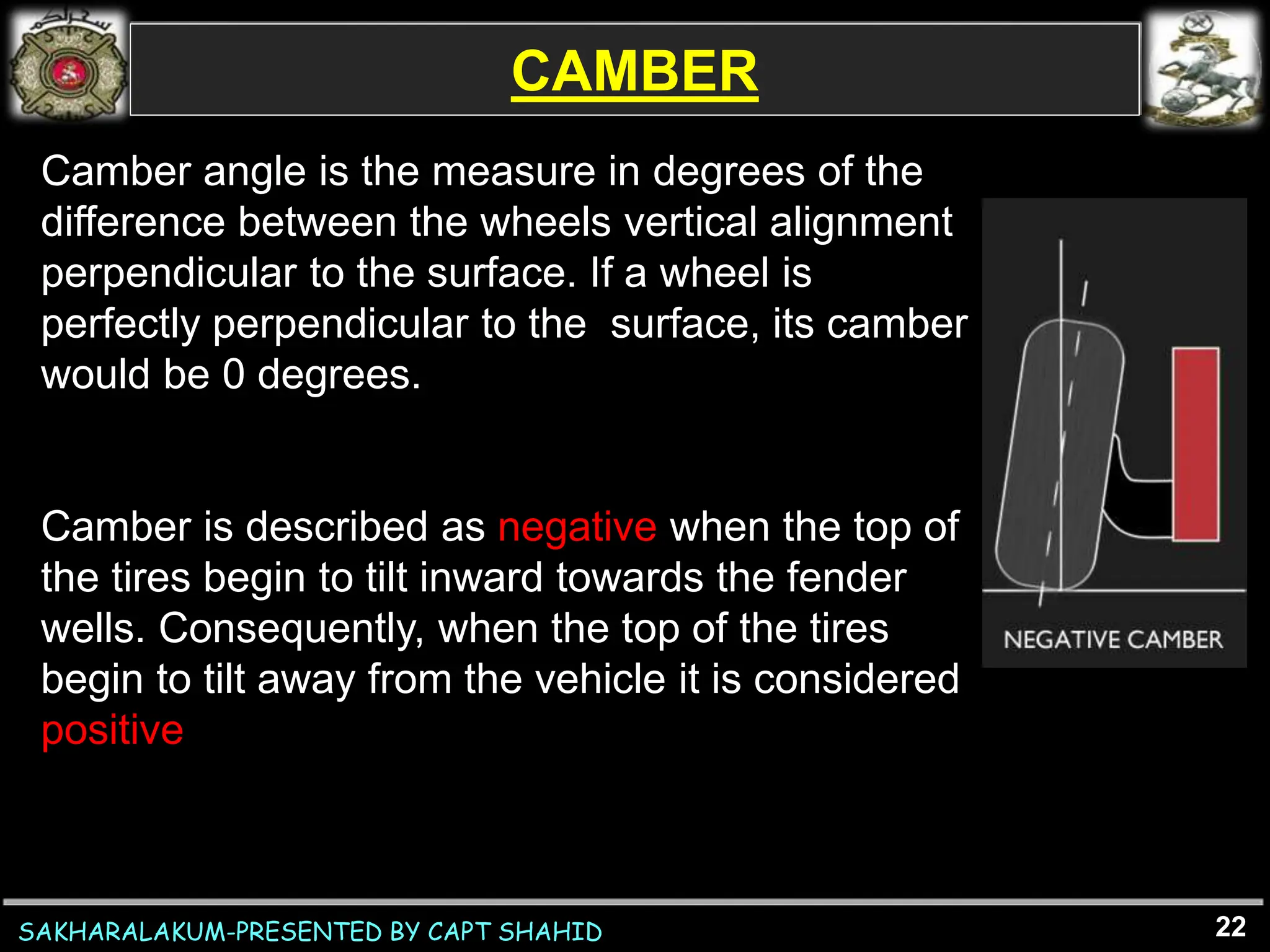
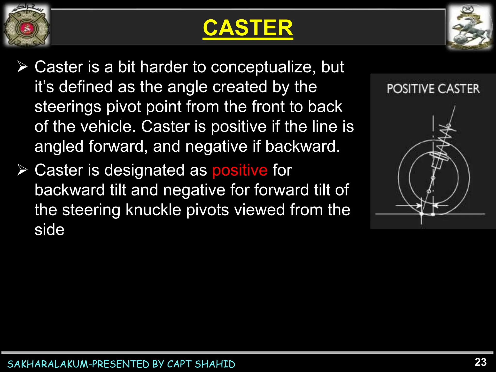
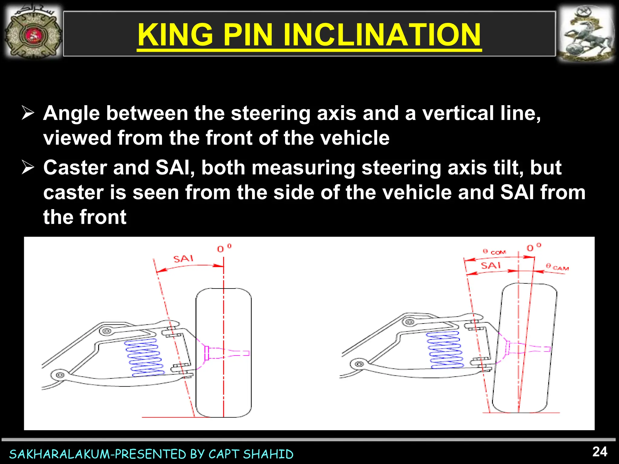
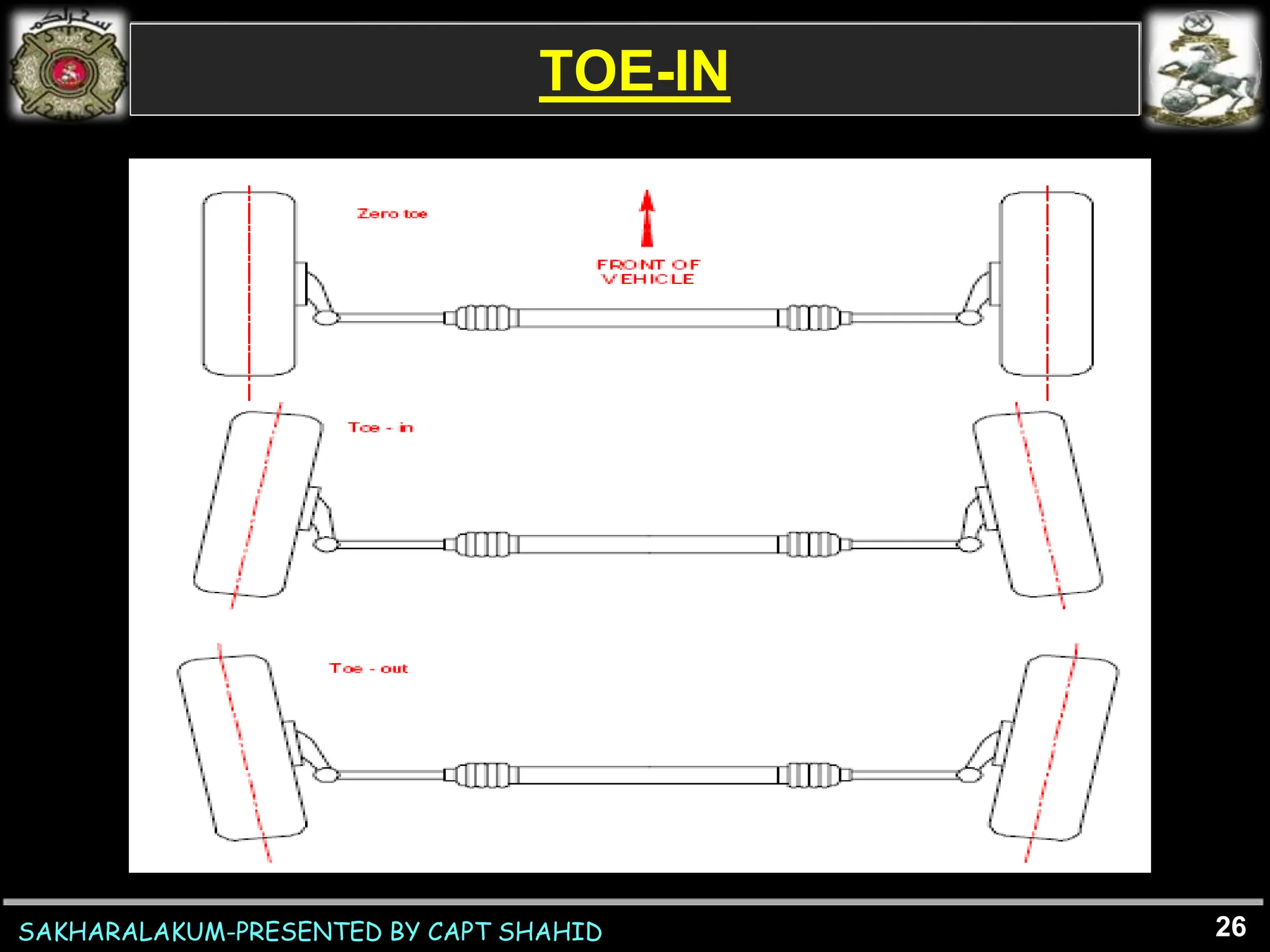
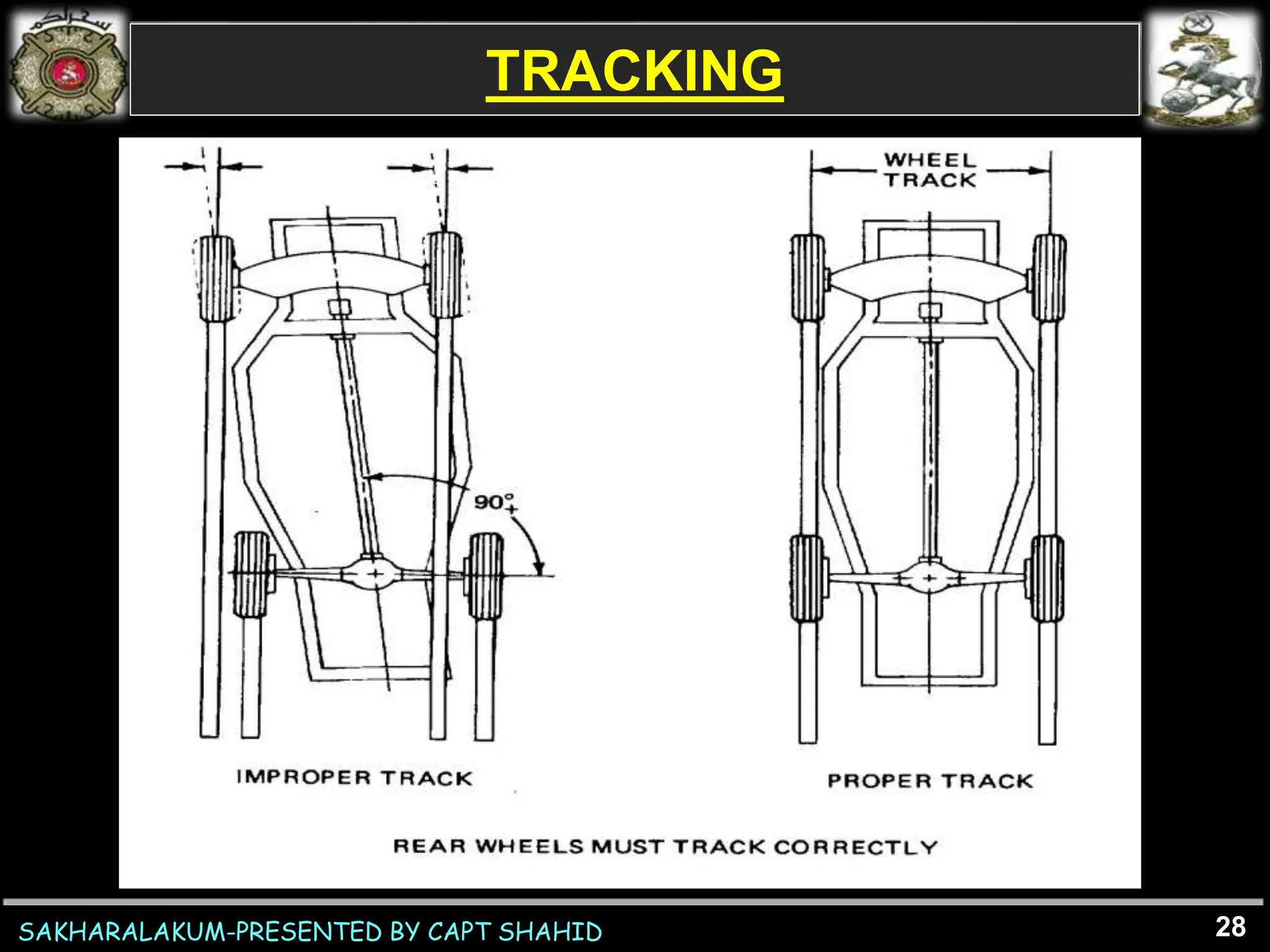
SAKHARALAKUM-PRESENTED BY CAPT SHAHID
STEERING GEOMETRY
2
SAKHARALAKUM-PRESENTED BY CAPT SHAHID
AIM
To acquaint student offrs regarding steering
geometry
3
SAKHARALAKUM-PRESENTED BY CAPT SHAHID
SEQ
 Intro
 Steering methods
• Fifth Wheel Steering Method
• Ackerman Steering Method
 Parts of steering system
 Parameters effecting steering
 Q & A
4
SAKHARALAKUM-PRESENTED BY CAPT SHAHID
INTRO
 When a vehicle is steered, it follows a path which is part of
the circumference of its turning circle, which will have a
centre point somewhere along a line extending from the axis
of the fixed axle
 The steered wheels must be angled so that they are both at
90 degrees to a line drawn from the circle centre through the
centre of the wheel
 Wheel on the outside of the turn trace a larger circle than the
wheel on the inside, the wheels need to be set at different
angles
5
SAKHARALAKUM-PRESENTED BY CAPT SHAHID
STEERING METHODS
 Fifth Wheel Steering Method
 Ackerman Steering Method
6
SAKHARALAKUM-PRESENTED BY CAPT SHAHID
FIFTH WHEEL STEERING METHOD
7
SAKHARALAKUM-PRESENTED BY CAPT SHAHID
FIFTH WHEEL STEERING METHOD
8
 On basis of fifth wheel steering method following
linkages are used in steering system
• Rack and pinion steering linkage
• Ball and socket joint linkage
• Solid axle steering linkage
SAKHARALAKUM-PRESENTED BY CAPT SHAHID
RACK AND PINION STEERING LINKAGE
9
SAKHARALAKUM-PRESENTED BY CAPT SHAHID
BALL SOCKET JOINT LINKAGE
 A ball socket joint used to connect the tie rod
assembly to the rack and pinion steering gear
 The threaded end of the socket assembly accepts
the tie rod and allows for toe adjustment
 Clamps are used to secure the tie rod and socket
joint
10
SAKHARALAKUM-PRESENTED BY CAPT SHAHID
BALL SOCKET JOINT LINKAGE
11
SAKHARALAKUM-PRESENTED BY CAPT SHAHID
SOLID AXLE STEERING LINKAGE
• Connects the pitman arm to the steering Linkage
• Springs to cushion shocks and prevent transmission of
the shocks to the steering gear
• Housing is provided on one end to receive the ball end of
the pitman arm
• The end of the drag link connected to the steering knuckle
arm is usually somewhat similar though it may be like a tie
rod end
12
SAKHARALAKUM-PRESENTED BY CAPT SHAHID
SOLID AXLE STEERING LINKAGE
13
SAKHARALAKUM-PRESENTED BY CAPT SHAHID
ACKERMAN STEERING METHOD
 Ackermann steering geometry ensures that at any
angle of steering, the centre point of all of the circles
traced by all wheels will lie at a common point by
setting different angles for the front wheels
automatically.
14
SAKHARALAKUM-PRESENTED BY CAPT SHAHID
 Ackermann angle varies with turning radius R
 Ackermann factor is the ratio between the actual
angle between the front wheels and the full
Ackermann angle
15
ACKERMAN STEERING METHOD
SAKHARALAKUM-PRESENTED BY CAPT SHAHID
PARALLELOGRAM STEERING LINKAGE
 Centerlink
connect the steering arms together
The turning action of the steering box is transmitted
to the center link through the pitman arm
The pitman arm also provides support for the center
link
two components are connected by a hinge or ball
joint
 Idler Arm
The center link is hinged on the opposite end of the
pitman arm by means of an idler arm
supports the free end of the center link allows it to
move left and right with ease
16
SAKHARALAKUM-PRESENTED BY CAPT SHAHID
PARALLELOGRAM STEERING LINKAGE
17
SAKHARALAKUM-PRESENTED BY CAPT SHAHID
PARTS OF STEERING SYSTEM
 Steering Arms
Bent toward each other
Left side arm is shaped like a bellcrank and accepts
the drag link and tie rod
 Tie Rod
Connects the steering arms together
Located in front of or behind the centerline of the
wheel
18
SAKHARALAKUM-PRESENTED BY CAPT SHAHID
PARTS OF STEERING SYSTEM
 Tie Rod Ends
Form a flexible link between the tie rod and steering
arm
Fastened to the knuckle arm with a tapered stud
A socket is provided within the tie rod end to hold the
end of the stud, which is in the form of a ball or yoke
The socket also allows movement between the
knuckle arm and the tie rod
A lubrication fitting usually is provided to keep the
ball and socket joint properly lubricated
A dust seal covers the tie rod end
19
SAKHARALAKUM-PRESENTED BY CAPT SHAHID
PARTS OF STEERING SYSTEM
 Adjusting Sleeves
The inner and outer tie rods are connected by
adjusting sleeves
tubular in design and threaded over the inner and
outer tie rods
provide a location for toe adjustment
Clamps and clamp bolts are used to secure the
sleeves
20
SAKHARALAKUM-PRESENTED BY CAPT SHAHID
FACTORS AFFECTING STEERING
 Camber
 Caster
 King pin inclination
 Toe-In / Toe-Out
 Tracking
21
SAKHARALAKUM-PRESENTED BY CAPT SHAHID
CAMBER
22
Camber angle is the measure in degrees of the
difference between the wheels vertical alignment
perpendicular to the surface. If a wheel is
perfectly perpendicular to the surface, its camber
would be 0 degrees.
Camber is described as negative when the top of
the tires begin to tilt inward towards the fender
wells. Consequently, when the top of the tires
begin to tilt away from the vehicle it is considered
positive
SAKHARALAKUM-PRESENTED BY CAPT SHAHID
CASTER
23
 Caster is a bit harder to conceptualize, but
it’s defined as the angle created by the
steerings pivot point from the front to back
of the vehicle. Caster is positive if the line is
angled forward, and negative if backward.
 Caster is designated as positive for
backward tilt and negative for forward tilt of
the steering knuckle pivots viewed from the
side
SAKHARALAKUM-PRESENTED BY CAPT SHAHID
KING PIN INCLINATION
 Angle between the steering axis and a vertical line,
viewed from the front of the vehicle
 Caster and SAI, both measuring steering axis tilt, but
caster is seen from the side of the vehicle and SAI from
the front
24
SAKHARALAKUM-PRESENTED BY CAPT SHAHID
TOE-IN
 Amount in inches that the wheels point in, that
is the distanc between the front wheels is less
at the front than it is at the rear
 Toe-in balances the effect of camber
 Adjustable by changing the length of the tie rod
25
SAKHARALAKUM-PRESENTED BY CAPT SHAHID
TOE-IN
26
SAKHARALAKUM-PRESENTED BY CAPT SHAHID
TRACKING
 Ability of the vehicle to maintain a right angle
between the centerline of the vehicle and both
the front and rear axles or spindles
 If this angle is off, the vehicle will appear to be
going sideways down a straight road
 This problem could be caused by shifted or
broken leaf springs or a bent or broken rear axle
or control arms
27
SAKHARALAKUM-PRESENTED BY CAPT SHAHID
TRACKING
28
SAKHARALAKUM-PRESENTED BY CAPT SHAHID 29
SAKHARALAKUM-PRESENTED BY CAPT SHAHID 30
SAKHARALAKUM-PRESENTED BY CAPT SHAHID 31
SAKHARALAKUM-PRESENTED BY CAPT SHAHID 32
SAKHARALAKUM-PRESENTED BY CAPT SHAHID
Q & A
33
SAKHARALAKUM-PRESENTED BY CAPT SHAHID
THANK YOU
34

Steering Geometry.ppt

  • 2.
    SAKHARALAKUM-PRESENTED BY CAPTSHAHID STEERING GEOMETRY 2
  • 3.
    SAKHARALAKUM-PRESENTED BY CAPTSHAHID AIM To acquaint student offrs regarding steering geometry 3
  • 4.
    SAKHARALAKUM-PRESENTED BY CAPTSHAHID SEQ  Intro  Steering methods • Fifth Wheel Steering Method • Ackerman Steering Method  Parts of steering system  Parameters effecting steering  Q & A 4
  • 5.
    SAKHARALAKUM-PRESENTED BY CAPTSHAHID INTRO  When a vehicle is steered, it follows a path which is part of the circumference of its turning circle, which will have a centre point somewhere along a line extending from the axis of the fixed axle  The steered wheels must be angled so that they are both at 90 degrees to a line drawn from the circle centre through the centre of the wheel  Wheel on the outside of the turn trace a larger circle than the wheel on the inside, the wheels need to be set at different angles 5
  • 6.
    SAKHARALAKUM-PRESENTED BY CAPTSHAHID STEERING METHODS  Fifth Wheel Steering Method  Ackerman Steering Method 6
  • 7.
    SAKHARALAKUM-PRESENTED BY CAPTSHAHID FIFTH WHEEL STEERING METHOD 7
  • 8.
    SAKHARALAKUM-PRESENTED BY CAPTSHAHID FIFTH WHEEL STEERING METHOD 8  On basis of fifth wheel steering method following linkages are used in steering system • Rack and pinion steering linkage • Ball and socket joint linkage • Solid axle steering linkage
  • 9.
    SAKHARALAKUM-PRESENTED BY CAPTSHAHID RACK AND PINION STEERING LINKAGE 9
  • 10.
    SAKHARALAKUM-PRESENTED BY CAPTSHAHID BALL SOCKET JOINT LINKAGE  A ball socket joint used to connect the tie rod assembly to the rack and pinion steering gear  The threaded end of the socket assembly accepts the tie rod and allows for toe adjustment  Clamps are used to secure the tie rod and socket joint 10
  • 11.
    SAKHARALAKUM-PRESENTED BY CAPTSHAHID BALL SOCKET JOINT LINKAGE 11
  • 12.
    SAKHARALAKUM-PRESENTED BY CAPTSHAHID SOLID AXLE STEERING LINKAGE • Connects the pitman arm to the steering Linkage • Springs to cushion shocks and prevent transmission of the shocks to the steering gear • Housing is provided on one end to receive the ball end of the pitman arm • The end of the drag link connected to the steering knuckle arm is usually somewhat similar though it may be like a tie rod end 12
  • 13.
    SAKHARALAKUM-PRESENTED BY CAPTSHAHID SOLID AXLE STEERING LINKAGE 13
  • 14.
    SAKHARALAKUM-PRESENTED BY CAPTSHAHID ACKERMAN STEERING METHOD  Ackermann steering geometry ensures that at any angle of steering, the centre point of all of the circles traced by all wheels will lie at a common point by setting different angles for the front wheels automatically. 14
  • 15.
    SAKHARALAKUM-PRESENTED BY CAPTSHAHID  Ackermann angle varies with turning radius R  Ackermann factor is the ratio between the actual angle between the front wheels and the full Ackermann angle 15 ACKERMAN STEERING METHOD
  • 16.
    SAKHARALAKUM-PRESENTED BY CAPTSHAHID PARALLELOGRAM STEERING LINKAGE  Centerlink connect the steering arms together The turning action of the steering box is transmitted to the center link through the pitman arm The pitman arm also provides support for the center link two components are connected by a hinge or ball joint  Idler Arm The center link is hinged on the opposite end of the pitman arm by means of an idler arm supports the free end of the center link allows it to move left and right with ease 16
  • 17.
    SAKHARALAKUM-PRESENTED BY CAPTSHAHID PARALLELOGRAM STEERING LINKAGE 17
  • 18.
    SAKHARALAKUM-PRESENTED BY CAPTSHAHID PARTS OF STEERING SYSTEM  Steering Arms Bent toward each other Left side arm is shaped like a bellcrank and accepts the drag link and tie rod  Tie Rod Connects the steering arms together Located in front of or behind the centerline of the wheel 18
  • 19.
    SAKHARALAKUM-PRESENTED BY CAPTSHAHID PARTS OF STEERING SYSTEM  Tie Rod Ends Form a flexible link between the tie rod and steering arm Fastened to the knuckle arm with a tapered stud A socket is provided within the tie rod end to hold the end of the stud, which is in the form of a ball or yoke The socket also allows movement between the knuckle arm and the tie rod A lubrication fitting usually is provided to keep the ball and socket joint properly lubricated A dust seal covers the tie rod end 19
  • 20.
    SAKHARALAKUM-PRESENTED BY CAPTSHAHID PARTS OF STEERING SYSTEM  Adjusting Sleeves The inner and outer tie rods are connected by adjusting sleeves tubular in design and threaded over the inner and outer tie rods provide a location for toe adjustment Clamps and clamp bolts are used to secure the sleeves 20
  • 21.
    SAKHARALAKUM-PRESENTED BY CAPTSHAHID FACTORS AFFECTING STEERING  Camber  Caster  King pin inclination  Toe-In / Toe-Out  Tracking 21
  • 22.
    SAKHARALAKUM-PRESENTED BY CAPTSHAHID CAMBER 22 Camber angle is the measure in degrees of the difference between the wheels vertical alignment perpendicular to the surface. If a wheel is perfectly perpendicular to the surface, its camber would be 0 degrees. Camber is described as negative when the top of the tires begin to tilt inward towards the fender wells. Consequently, when the top of the tires begin to tilt away from the vehicle it is considered positive
  • 23.
    SAKHARALAKUM-PRESENTED BY CAPTSHAHID CASTER 23  Caster is a bit harder to conceptualize, but it’s defined as the angle created by the steerings pivot point from the front to back of the vehicle. Caster is positive if the line is angled forward, and negative if backward.  Caster is designated as positive for backward tilt and negative for forward tilt of the steering knuckle pivots viewed from the side
  • 24.
    SAKHARALAKUM-PRESENTED BY CAPTSHAHID KING PIN INCLINATION  Angle between the steering axis and a vertical line, viewed from the front of the vehicle  Caster and SAI, both measuring steering axis tilt, but caster is seen from the side of the vehicle and SAI from the front 24
  • 25.
    SAKHARALAKUM-PRESENTED BY CAPTSHAHID TOE-IN  Amount in inches that the wheels point in, that is the distanc between the front wheels is less at the front than it is at the rear  Toe-in balances the effect of camber  Adjustable by changing the length of the tie rod 25
  • 26.
  • 27.
    SAKHARALAKUM-PRESENTED BY CAPTSHAHID TRACKING  Ability of the vehicle to maintain a right angle between the centerline of the vehicle and both the front and rear axles or spindles  If this angle is off, the vehicle will appear to be going sideways down a straight road  This problem could be caused by shifted or broken leaf springs or a bent or broken rear axle or control arms 27
  • 28.
  • 29.
  • 30.
  • 31.
  • 32.
  • 33.
  • 34.
    SAKHARALAKUM-PRESENTED BY CAPTSHAHID THANK YOU 34

Editor's Notes

  • #23 Effect Negative camber is becoming increasingly more popular because of its visual appeal. The real advantages to negative camber are seen in the handling characteristics. An aggressive driver will enjoy the benefits of increased grip during heavy cornering with negative camber. During straight acceleration however, negative camber will reduce the contact surface between the tires and road surface. Negative camber generates what is referred to as camber thrust. When both tires are angled negatively they push against each other, which is fine as long as both tires are in contact with the road surface. When one tire loses grip, the other tire no longer has an opposing force being applied to it and as a result the vehicle is thrust towards the wheel with no traction. Zero camber will result in more even tire wear over time, but may rob performance during cornering. Ultimately, optimal camber will depend upon your driving style and conditions the vehicle is being driven in.
  • #24 Effect Negative camber is becoming increasingly more popular because of its visual appeal. The real advantages to negative camber are seen in the handling characteristics. An aggressive driver will enjoy the benefits of increased grip during heavy cornering with negative camber. During straight acceleration however, negative camber will reduce the contact surface between the tires and road surface. Negative camber generates what is referred to as camber thrust. When both tires are angled negatively they push against each other, which is fine as long as both tires are in contact with the road surface. When one tire loses grip, the other tire no longer has an opposing force being applied to it and as a result the vehicle is thrust towards the wheel with no traction. Zero camber will result in more even tire wear over time, but may rob performance during cornering. Ultimately, optimal camber will depend upon your driving style and conditions the vehicle is being driven in.
  • #27 Correct toe is paramount to even tread wear and extended tire life. If the tires are pointed inward or outward, they will scrub against the surface of the road and cause wear along the edges. Sometimes however, tread life can be sacrificed for performance or stability Positive toe occurs when the front of both tires begins to face each other. Positive toe permits both wheels to constantly generate force against one another, which reduces turning ability. However, positive tow creates straighter driving characteristics. Typically, rear wheel drive vehicles have slightly positive tow in the rear due to rolling resistance – causing outward drag in the suspension arms. The slight positive toe straightens out the wheels at speed, effectively evening them out and preventing excessive tire wear. Negative toe is often used in front wheel drive vehicles for the opposite reason. Their suspension arms pull slightly inward, so a slight negative toe will compensate for the drag and level out the wheels at speed. Negative toe increases a cars cornering ability. When the vehicle begins to turn inward towards a corner, the inner wheel will be angled more aggressively. Since its turning radius is smaller than the outer wheel due to the angle, it will pull the car in that direction. Negative toe decreases straight line stability as a result. Any slight change in direction will cause the car to hint towards one direction or the other.