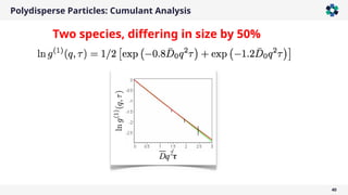
Downloaded 16 times


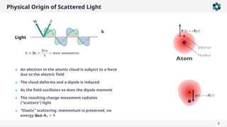
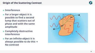
![Field Correlation Function
34
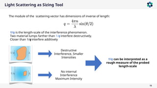
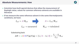
Upon normalization:
Identical Independent
Particles
It can be modeled, but cannot be measured!
The electric field correlation function is important as it is directly connected
to colloid dynamics models
∑
𝑗 ,𝑘
𝐹 𝑗 (𝑞)𝐹𝑘
∗
(𝑞)exp{−𝑖𝒒⋅[𝒓 𝑗 (0)−𝒓𝑘 (𝜏)]}
⟨𝐸(𝒒,0)𝐸
∗
(𝒒,𝜏)⟩ ∑
𝑗,𝑘
𝐹𝑗 (𝑞)exp{−𝑖𝒒⋅𝒓 𝑗 (0)}ℑ(𝐹𝑘(𝑞)exp{−𝑖𝒒⋅𝒓𝑘 (𝜏)})](https://image.slidesharecdn.com/lightscatteringfundamentalssimpler-250108091625-4a55b85c/85/Static-and-Dynamic-Light-Scattering-Fundamentals-2025-34-320.jpg)

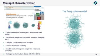
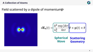
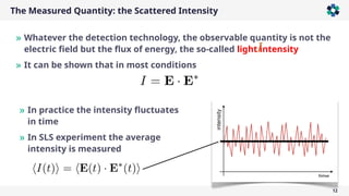
![Microgel Characterization
50
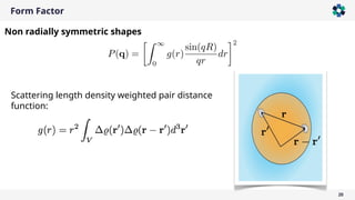
Δ 𝜌 (𝑟 )∝ ∫
− ∞
∞
Θ [𝑥 − 𝑅 ] 1
𝜎 √2 𝜋
𝑒
−
(𝑟 −𝑥 )
2
2 𝜎
2
𝑑𝑥=
1
2
erfc
[𝑟 − 𝑅
√2 𝜎 ]
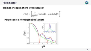
𝑃 (𝑞) ∝
3[sin (𝑞𝑅)−𝑞𝑅 cos(𝑞𝑅)]
(𝑞𝑅)
3
exp[−
(𝜎 𝑞)2
2 ]
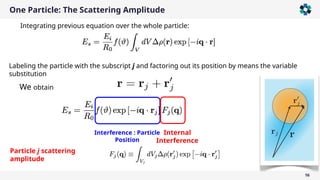
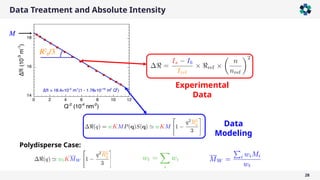
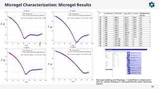
*M. Stieger, W. Richtering, J. S. Pedersen, and P. Lindner, Small-angle neutron scattering study of structural
changes in temperature sensitive microgel colloids, The Journal of Chemical Physics 120, 6197 (2004). More
than 500 citations.
‘Smeared’ density profile
𝑟 [nm ]
𝜌 (𝑟 )[arb. u]
𝑟 [nm ]
sphere
Fuzzy
sphere
𝜌 (𝑟 )[arb. u]
The fuzzy sphere model](https://image.slidesharecdn.com/lightscatteringfundamentalssimpler-250108091625-4a55b85c/85/Static-and-Dynamic-Light-Scattering-Fundamentals-2025-50-320.jpg)
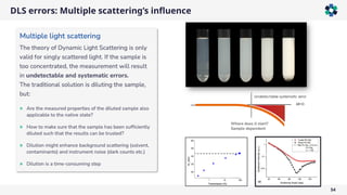
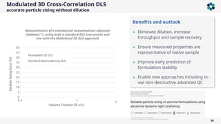


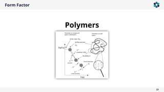
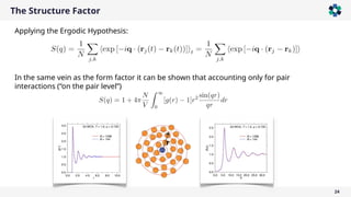
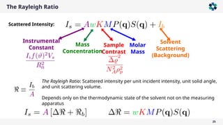
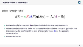
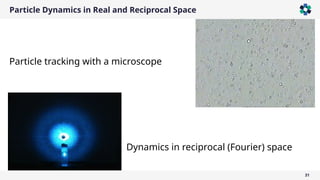
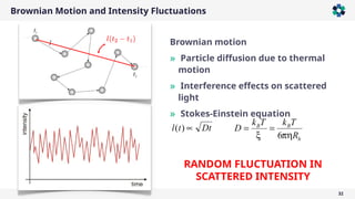
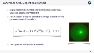
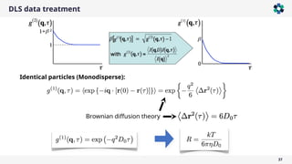
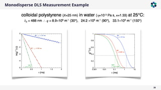
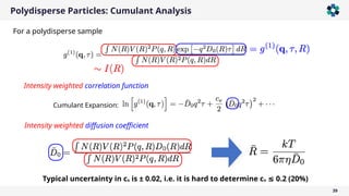
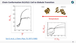
The document is a company presentation by Andrea Vaccaro focused on the fundamentals and applications of light scattering, particularly static light scattering (SLS) and dynamic light scattering (DLS). It covers theoretical aspects, practical implementations, and the challenges associated with analyzing concentrated systems, as well as advancements in measurement techniques for improved accuracy. Key topics include particle sizing, characterization of polymers and microgels, and the significance of scattering techniques in material science and nanotechnology.


![谷歌留痕技术 [ 𝙩𝙤𝙥 𝟮𝟯𝟯. 𝙘 𝙤𝙢 ]](https://cdn.slidesharecdn.com/ss_thumbnails/top233-260130174328-3833018c-thumbnail.jpg?width=640&height=640&fit=bounds)
