The document provides details on staircases including:
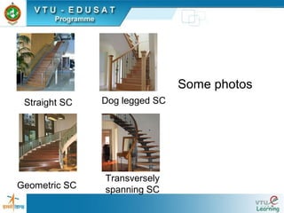
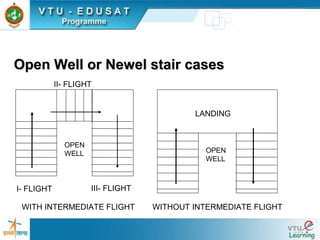
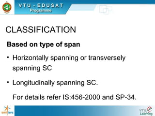
1) Types of staircases such as straight, dog-legged, and spiral.
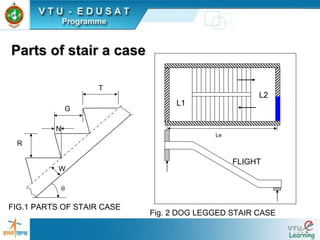
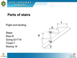
2) Requirements for staircase dimensions including tread, rise, and pitch.
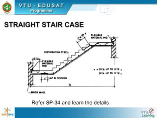
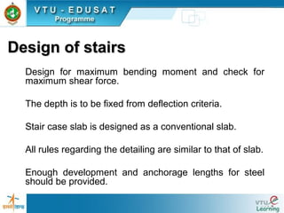
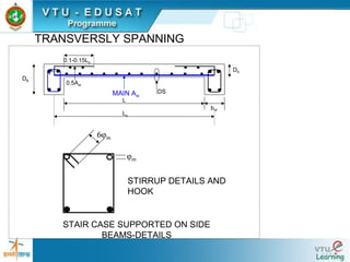
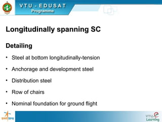
3) Detailing principles for steel in staircases including main steel, distribution steel, and anchorage.
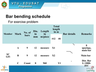
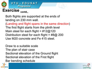
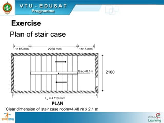
4) An example of detailing a dog-legged staircase with given dimensions and reinforcement details.


![Guide lines for fixing the dimensionsGuide lines for fixing the dimensions
Rise (R) : 150mm to 180mm
Tread (T) : 220 mm to 250 mm- for residential buildings.
Rise (R) : 120 to 150 mm
Tread (T) : 250 mm to 300 mm – for public buildings
[T + 2R] : Between 500 mm to 650 mm
The width of the stair
• 0.8 m to 1 m for residential building and
• 1.8 m to 2 m for public building.](https://image.slidesharecdn.com/staircases-130520232545-phpapp01/85/How-do-you-takeoff-a-staircase-12-320.jpg)


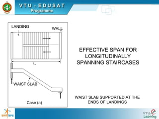
![EFFECTIVE SPAN FOR
LONGITUDINALLY
SPANNING STAIRCASES
X X Y Y
Le
Case (c)
Case (b)
Le
Le=G +[ X +Y], X ≤1m AND Y ≤1m
Le=c/c of beams
GOING=G](https://image.slidesharecdn.com/staircases-130520232545-phpapp01/85/How-do-you-takeoff-a-staircase-18-320.jpg)


![ROW OF CHAIRS
500 mm
500 mm
GL
Wall
FOUNDATION
GROUND FLIGHT
MAIN STEEL
# 12 @ 120
DIST. STEEL
# 8 @ 200
150
Ld =564
REINFORCEMENT
FROM BM
Ld =564
FLOOR LEVEL
LANDING FIRST FLIGHT
R=160
T= 250
LAP L
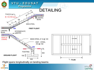
DETAILING
Landing and flight spans longitudinally
[A]
[C]
[D,E]-
Anchorage
steel
Main steel [B]](https://image.slidesharecdn.com/staircases-130520232545-phpapp01/85/How-do-you-takeoff-a-staircase-24-320.jpg)